
Related Manuals for Huawei USG9500 Series


Summary of Contents for Huawei USG9500 Series
- Page 1 HUAWEI USG9500 Series V300R001 & V500R001 Hardware Guide Issue Date 2017-12-15 HUAWEI TECHNOLOGIES CO., LTD.
- Page 2 Notice The purchased products, services and features are stipulated by the contract made between Huawei and the customer. All or part of the products, services and features described in this document may not be within the purchase scope or the usage scope. Unless otherwise specified in the contract, all statements, information, and recommendations in this document are provided "AS IS"...
-
Page 3: About This Document
Indicates an imminently hazardous situation which, if not avoided, will result in death or serious injury. Indicates a potentially hazardous situation which, if not avoided, could result in death or serious injury. Issue 03 (2017-12-15) Huawei Proprietary and Confidential Copyright © Huawei Technologies Co., Ltd. - Page 4 Several items or no item can be selected. &<1-n> The parameter before the & sign can be repeated 1 to n times. A line starting with the # sign is comments. Issue 03 (2017-12-15) Huawei Proprietary and Confidential Copyright © Huawei Technologies Co., Ltd.
- Page 5 Added the support of the 1.25 Gbit/s SFP/eSFP optical transceiver for the 10GBase LAN/ WAN-SFP+Flexible card optical interface. For details, see 1.5.2 1.25 Gbit/s SFP/eSFP Optical Module. Updates in Issue 01 (2017-03-28) V500R001C50 Initial commercial release. Issue 03 (2017-12-15) Huawei Proprietary and Confidential Copyright © Huawei Technologies Co., Ltd.
-
Page 6: Table Of Contents
1.2.5 Heat Dissipation System............................44 1.2.5.1 System Air Channel..............................44 1.2.5.2 Fan Module................................45 1.2.5.3 Air Filter................................. 47 1.2.6 Switch Frabric................................47 1.2.7 Control Plane................................49 1.2.8 Technical Specifications............................49 1.3 USG9520..................................52 Issue 03 (2017-12-15) Huawei Proprietary and Confidential Copyright © Huawei Technologies Co., Ltd. - Page 7 1.4.4.12 Firewall Performance Expansion Card (SPCB-20-O-H&M)................132 1.4.4.13 Application Security Service Processing Card (SPC-APPSEC-FW)..............133 1.4.4.14 Application Security Service Processing Card (SPC-IPS-20)................135 1.4.4.15 Enhanced Application Security Service Processing Card A (SPCA-APPSEC-FW)......... 137 Issue 03 (2017-12-15) Huawei Proprietary and Confidential Copyright © Huawei Technologies Co., Ltd.
- Page 8 1.4.9.5 1-port 10GBase LAN/WAN-XFP FPIC (1 x 10GBase LAN/WAN)..............192 1.4.9.6 4-Port 10GBase WAN/LAN-XFP FPIC (4x10GBase LAN/WAN)..............194 1.4.10 1-Port 100GBase-CFP Integrated Line Processing Unit (LPUI-101)..............196 1.5 Optical/Electrical Module............................197 1.5.1 1 Gbit/s Electrical Transceiver..........................198 Issue 03 (2017-12-15) Huawei Proprietary and Confidential Copyright © Huawei Technologies Co., Ltd.
- Page 9 2.3.9 Connecting Optical Fibers............................286 2.3.10 Checking After Installation........................... 289 2.3.11 Powering On the USG9560 - DC Power Distribution...................290 2.3.12 Powering On the USG9560 - AC Power Distribution...................293 Issue 03 (2017-12-15) Huawei Proprietary and Confidential viii Copyright © Huawei Technologies Co., Ltd.
- Page 10 3.3.2 Replacing the Fan Module of the USG9560......................376 3.3.3 Replacing the Fan Module of the USG9520......................379 3.4 Replacing Power Modules............................381 3.4.1 Replacing the DC PEM of the USG9580........................ 382 Issue 03 (2017-12-15) Huawei Proprietary and Confidential Copyright © Huawei Technologies Co., Ltd.
- Page 11 A.2.3.2 Assembling the Unshielded RJ45 Connector and the Ethernet Cable..............459 A.2.3.3 Checking Metal Contact Strips..........................461 A.2.3.4 Testing the Connection of Assembled Cables..................... 463 A.3 Environmental Requirements for Device Running....................466 Issue 03 (2017-12-15) Huawei Proprietary and Confidential Copyright © Huawei Technologies Co., Ltd.
- Page 12 A.5.6.1 Engineering Labels for DC Power Cables......................497 A.5.6.2 Engineering Labels for AC Power Cables......................498 A.6 Requirements for Customers' Cabinets Purchased from Other Vendors..............499 A.7 Fault Tag..................................501 Issue 03 (2017-12-15) Huawei Proprietary and Confidential Copyright © Huawei Technologies Co., Ltd.
-
Page 13: Hardware Overview
Hardware Guide 1 Hardware Overview Hardware Overview About This Chapter This chapter provides hardware information about the USG9500 series, including the hardware appearance, power supply system, heat dissipation system, and technical specifications. 1.1 USG9580 The USG9580 is a 32 U device. It employs an integrated chassis and has 16 LPU/SPU slots. -
Page 14: Usg9580
This section describes the appearance and hardware system features of the USG9580. Appearance The USG9580 has an integrated chassis and adopts a centralized routing engine and a distributed forwarding architecture. Figure 1-1 shows the chassis of the USG9580. Issue 03 (2017-12-15) Huawei Proprietary and Confidential Copyright © Huawei Technologies Co., Ltd. - Page 15 Distributed hardware-based forwarding and rapid service deployment Compact structure for increasing interface density Normalized system component design Separation of control, service, and monitoring channels for ensuring non-blocking of control and monitoring channels Issue 03 (2017-12-15) Huawei Proprietary and Confidential Copyright © Huawei Technologies Co., Ltd.
-
Page 16: Usg9580 Components
The section describes the main components on the front and rear panels of the USG9580. The USG9580 has an integrated chassis. Figure 1-2 Figure 1-3 show the architecture and main components of the USG9580. Issue 03 (2017-12-15) Huawei Proprietary and Confidential Copyright © Huawei Technologies Co., Ltd. - Page 17 The USG9580 MPUs work in 1:1 backup mode. When the active MPU is faulty, the standby MPU immediately takes over for it, ensuring service continuity. LPU/SPU Holds an LPU or SPU. slot Issue 03 (2017-12-15) Huawei Proprietary and Confidential Copyright © Huawei Technologies Co., Ltd.
- Page 18 Front Used for laying optical fibers and cables. It is divided into the upper cable rack and lower racks. "HUAWEI" is written on the upper cable rack, while "USG9500 Series" appears on the lower cable rack. Rear Panel Figure 1-3 USG9580 rear panel Lifting Hazard.May result in injury or...
-
Page 19: Slot Layout And Boards
USG9580. Figure 1-4 USG9580 slot layout 1 2 3 17 18 4 5 6 7 8 9 10 11 12 13 14 15 16 Issue 03 (2017-12-15) Huawei Proprietary and Confidential Copyright © Huawei Technologies Co., Ltd. - Page 20 1.4.4.9 Firewall Service Processing Unit (SPUB-20-O-H, for USG9560/USG9580) 1.4.4.10 Firewall Performance 0305G09V Expansion Card (SPC-20-O-E8KE) 03057429 1.4.4.11 Firewall Performance Expansion Card (SPCA-20-O-H&M) 03057522 1.4.4.12 Firewall Performance Expansion Card (SPCB-20-O-H&M) Issue 03 (2017-12-15) Huawei Proprietary and Confidential Copyright © Huawei Technologies Co., Ltd.
- Page 21 1.4.6.2 20-Port 10/100/1000Base-RJ45 FPIC (FW-20X1G-RJ45) 03056633 1.4.6.3 24-Port 100/1000 Base-X-SFP FPIC (E8KE-X-101-24XGE-SFP) 03056632 1.4.6.4 5-Port 10GBase LAN/WAN-SFP + FPIC A (E8KE-X-101-5X10GE-SFP+) 03056684 1.4.6.5 6*10GE SFP+ Daughter Card (FW-6X10GE-SFP+) Issue 03 (2017-12-15) Huawei Proprietary and Confidential Copyright © Huawei Technologies Co., Ltd.
- Page 22 1.4.9.3 12-port 100Base-FX/1000Base-X- 03056626 SFP FPIC (12x100/1000Base-SFP) 1.4.9.4 1-port OC-192c/STM-64c POS- 0305G055 XFP FPIC (1 x OC-192c/STM-64c POS- XFP) 1.4.9.5 1-port 10GBase LAN/WAN-XFP 03056625 FPIC (1 x 10GBase LAN/WAN) Issue 03 (2017-12-15) Huawei Proprietary and Confidential Copyright © Huawei Technologies Co., Ltd.
-
Page 23: Power Supply System
PEMs. As shown in Figure 1-5, the USG9580 backplane is divided into four areas, each with two power inputs. These eight power inputs work in backup mode. Issue 03 (2017-12-15) Huawei Proprietary and Confidential Copyright © Huawei Technologies Co., Ltd. -
Page 24: Dc Power Supply System
Table 1-3 Power supply solution of the USG9580 DC power system DC power Powered Area Powered Part module PEM-A1 Zone1 l Front panel: slots 5-7, 19-21 PEM-B1 l Rear panel: fan modules (upper left side) Issue 03 (2017-12-15) Huawei Proprietary and Confidential Copyright © Huawei Technologies Co., Ltd. - Page 25 Each DC power input contains one -48 V power input and one RTN input. Two separate RTN inputs join together on the board. Issue 03 (2017-12-15) Huawei Proprietary and Confidential Copyright © Huawei Technologies Co., Ltd.
- Page 26 A3 A4 B3 B4 RS485-2 -48~-60V;8.60A -48~-60V;8.60A -48~-60V;8.60A -48~-60V;8.60A PEM-A3 PEM-A4 128-270KG(282-595LBS) zone4 zone4 zone3 zone3 AN-B5/FFU-B7 zone3 zone3 zone4 zone4 Figure 1-7 shows the PEM. Issue 03 (2017-12-15) Huawei Proprietary and Confidential Copyright © Huawei Technologies Co., Ltd.
- Page 27 Table 1-5 Technical specifications of the DC PEM Item Technical Specification Type PEMB Dimensions (Width x 58 mm x 115 mm x 220 mm Depth x Height) Weight 1.1 kg Issue 03 (2017-12-15) Huawei Proprietary and Confidential Copyright © Huawei Technologies Co., Ltd.
-
Page 28: Ac Power Supply System
Rear panel: fan modules (lower left side) PEM-A4 Zone4 l Front panel: slots 8-12 PEM-B4 l Rear panel: fan modules (lower right side) NOTE PEMs A and B back up each other. Issue 03 (2017-12-15) Huawei Proprietary and Confidential Copyright © Huawei Technologies Co., Ltd. - Page 29 The two AC power chassis work in 1+1 backup mode. Each AC power chassis has four circuit breakers and eight AC power inputs. The current of each air circuit breaker is 20 Figure 1-9 Figure 1-10 show the AC power chassis. Issue 03 (2017-12-15) Huawei Proprietary and Confidential Copyright © Huawei Technologies Co., Ltd.
- Page 30 AC power chassis does not need to connect to the monitoring cable in the installation auxiliary material package. Table 1-7 describes indicators on the panel of the AC power chassis. Issue 03 (2017-12-15) Huawei Proprietary and Confidential Copyright © Huawei Technologies Co., Ltd.
- Page 31 Table 1-8 Technical specifications of the AC power supply module Item Technical Specification Type EPS200-4850A Dimensions (Width x 442 mm x 650 mm x 88 mm Depth x Height) Issue 03 (2017-12-15) Huawei Proprietary and Confidential Copyright © Huawei Technologies Co., Ltd.
-
Page 32: Heat Dissipation System
The middle area of the USG9580 is for SFU slots. The air intake vent in this area is located on the left side of the chassis. Two upper SFU slots in the area draw in air from the left side. Issue 03 (2017-12-15) Huawei Proprietary and Confidential Copyright © Huawei Technologies Co., Ltd. -
Page 33: Fan Module
96 hours and the accumulated operation time of the system per year does not exceed 15 days. Issue 03 (2017-12-15) Huawei Proprietary and Confidential Copyright © Huawei Technologies Co., Ltd. - Page 34 When the system is fully configured, fan speeds are adjusted based on temperatures reported by the temperature sensors on the LPUs, SPUs, SFUs and MPUs. Table 1-11 lists general fan speed adjustment principles. Issue 03 (2017-12-15) Huawei Proprietary and Confidential Copyright © Huawei Technologies Co., Ltd.
-
Page 35: Air Filter
The depth of the air filter is the same as that of an SFU, and the height of the air filter is four times the width of an SFU, as shown in Figure 1-14. Issue 03 (2017-12-15) Huawei Proprietary and Confidential Copyright © Huawei Technologies Co., Ltd. -
Page 36: Switch Fabric
E8KE-X16-SFUC-200SP. The switching network responsible for switching data between LPUs/SPUs is a key component of the USG9580. The USG9580 uses switching chips developed by Huawei and Memory-Crossbar-Memory (M-C-M) to provide three-level switching. Level-1 and level-3 switching use a shared-memory model and are performed on LPUs/SPUs; level-2 switching uses a Crossbar model and is performed on SFUs. -
Page 37: Control Plane
System Control and Management Unit As the system control and management unit, the MPU provides the following functions on the system control panel: Issue 03 (2017-12-15) Huawei Proprietary and Confidential Copyright © Huawei Technologies Co., Ltd. -
Page 38: Technical Specifications
Table 1-12 USG9580 Technical Specifications Item Description System specifications Processing unit of the Main frequency: 1.5 GHz BootROM capacity of 8 MB the MPU SDRAM capacity of the 4 GB Issue 03 (2017-12-15) Huawei Proprietary and Confidential Copyright © Huawei Technologies Co., Ltd. - Page 39 110 V rated voltage: 90 V AC to 175 V AC, 47 Hz to 63 Hz (The output power reduces to half of the maximum output when the input voltage is in the range of 90 V AC to 175 V AC.) Issue 03 (2017-12-15) Huawei Proprietary and Confidential Copyright © Huawei Technologies Co., Ltd.
- Page 40 5% RH to 95% RH, no coagulation term Storage relative humidity 0% RH to 95% RH Long-term altitude Lower than 3000 m Storage altitude Lower than 5000 m Issue 03 (2017-12-15) Huawei Proprietary and Confidential Copyright © Huawei Technologies Co., Ltd.
-
Page 41: Usg9560
This section describes the appearance and hardware system features of the USG9560. Appearance The USG9560 has an integrated chassis and adopts a centralized routing engine and a distributed forwarding architecture. Figure 1-16 shows the chassis of the USG9560. Issue 03 (2017-12-15) Huawei Proprietary and Confidential Copyright © Huawei Technologies Co., Ltd. - Page 42 U-shaped air channels for improving system heat dissipation Distributed power supply for enhancing power supply capabilities of a single chassis 200-mm fans SRUAs in 1:1 backup mode Issue 03 (2017-12-15) Huawei Proprietary and Confidential Copyright © Huawei Technologies Co., Ltd.
-
Page 43: Usg9560 Components
Name Description Air filter The air filters of the USG9560 are deployed on the air intake vents of chassis air channels to protect the device against dust. Issue 03 (2017-12-15) Huawei Proprietary and Confidential Copyright © Huawei Technologies Co., Ltd. - Page 44 NEG(-) RTN(+) RS485 Diagram of partitioned Power supply in the Syatem FAN A3 FAN B3 FFU A4 FFU B4 A1 A2 B1 B2 -48~-60V;8.60A -48~-60V;8.60A -48~-60V;8.60A -48~-60V;8.60A Issue 03 (2017-12-15) Huawei Proprietary and Confidential Copyright © Huawei Technologies Co., Ltd.
-
Page 45: Slot Layout And Supported Boards
USG9560. Figure 1-19 USG9560 slot layout 1 2 3 4 9 11 10 5 6 7 8 Table 1-13 describes the slot layout on the USG9560. Issue 03 (2017-12-15) Huawei Proprietary and Confidential Copyright © Huawei Technologies Co., Ltd. - Page 46 Expansion Card (SPC-20-O-E8KE) 03057429 1.4.4.11 Firewall Performance Expansion Card (SPCA-20-O-H&M) 03057522 1.4.4.12 Firewall Performance Expansion Card (SPCB-20-O-H&M) 03057872 1.4.4.15 Enhanced Application Security Service Processing Card A (SPCA- APPSEC-FW) Issue 03 (2017-12-15) Huawei Proprietary and Confidential Copyright © Huawei Technologies Co., Ltd.
- Page 47 1.4.6.3 24-Port 100/1000 Base-X-SFP FPIC (E8KE-X-101-24XGE-SFP) 03056632 1.4.6.4 5-Port 10GBase LAN/WAN-SFP + FPIC A (E8KE-X-101-5X10GE-SFP+) 03056684 1.4.6.5 6*10GE SFP+ Daughter Card (FW-6X10GE-SFP+) 03056686 1.4.6.6 12*10GE SFP+ Daughter Card (FW-12X10GE-SFP+) Issue 03 (2017-12-15) Huawei Proprietary and Confidential Copyright © Huawei Technologies Co., Ltd.
- Page 48 1.4.9.4 1-port OC-192c/STM-64c POS- 0305G055 XFP FPIC (1 x OC-192c/STM-64c POS- XFP) 1.4.9.5 1-port 10GBase LAN/WAN-XFP 03056625 FPIC (1 x 10GBase LAN/WAN) 1.4.9.6 4-Port 10GBase WAN/LAN-XFP 0305G07W FPIC (4x10GBase LAN/WAN) Issue 03 (2017-12-15) Huawei Proprietary and Confidential Copyright © Huawei Technologies Co., Ltd.
-
Page 49: Power Supply System
RS485 Diagram of partitioned Power supply in the Syatem FAN A3 FAN B3 FFU A4 FFU B4 A1 A2 B1 B2 -48~-60V;8.60A -48~-60V;8.60A Issue 03 (2017-12-15) Huawei Proprietary and Confidential Copyright © Huawei Technologies Co., Ltd. -
Page 50: Dc Power Supply System
NEG(-) RTN(+) NEG(-) RTN(+) NEG(-) RTN(+) NEG(-) RTN(+) -48~-60V;8.60A -48~-60V;8.60A -48~-60V;8.60A -48~-60V;8.60A Figure 1-22 shows the PEM. Issue 03 (2017-12-15) Huawei Proprietary and Confidential Copyright © Huawei Technologies Co., Ltd. - Page 51 Table 1-17 Technical specifications of the DC PEM Item Technical Specification Type PEMB Dimensions (Width x 58 mm x 115 mm x 220 mm Depth x Height) Weight 1.1 kg Issue 03 (2017-12-15) Huawei Proprietary and Confidential Copyright © Huawei Technologies Co., Ltd.
-
Page 52: Ac Power Supply System
AC power chassis, power modules, and chassis parts. Each DC power input contains one -48 V power input and one RTN input. Two separate RTN inputs join together on the board. Issue 03 (2017-12-15) Huawei Proprietary and Confidential Copyright © Huawei Technologies Co., Ltd. - Page 53 AC power chassis. The current of the air circuit breaker is 20 A. Figure 1-24 Figure 1-25 show the AC power chassis. Figure 1-24 Front view of the AC power chassis Power running indicator Protection indicator Fault indicator Issue 03 (2017-12-15) Huawei Proprietary and Confidential Copyright © Huawei Technologies Co., Ltd.
- Page 54 Color Normal Abnormal Cause Power running Green Power failure indicator (no AC input, over-voltage AC input, or under-voltage AC input) and no output from the power module Issue 03 (2017-12-15) Huawei Proprietary and Confidential Copyright © Huawei Technologies Co., Ltd.
- Page 55 Rated input voltage range l 220 V rated voltage: 200 V AC to 240 V AC, 50/60 Hz l 110 V rated voltage: 100 V AC to 120 V AC, 50/60 Hz Issue 03 (2017-12-15) Huawei Proprietary and Confidential Copyright © Huawei Technologies Co., Ltd.
-
Page 56: Heat Dissipation System
The air filter covers a large area and has a curved face and low small windage resistance. These features increase heat dissipation efficiency. The following figure shows the air flow in the USG9560. Issue 03 (2017-12-15) Huawei Proprietary and Confidential Copyright © Huawei Technologies Co., Ltd. -
Page 57: Fan Module
96 hours and the accumulated operation time of the system per year does not exceed 15 days. Issue 03 (2017-12-15) Huawei Proprietary and Confidential Copyright © Huawei Technologies Co., Ltd. - Page 58 When the system is fully configured, fan speeds are adjusted based on temperatures reported by the temperature sensors on the LPUs, SPUs, SFUs and MPUs. Table 1-23 lists general fan speed adjustment principles. Issue 03 (2017-12-15) Huawei Proprietary and Confidential Copyright © Huawei Technologies Co., Ltd.
-
Page 59: Air Filter
You are advised to remove and clean air filters at least once every three months. 1.2.6 Switch Frabric This section describes the mechanism of the switch fabric on the USG9560. Issue 03 (2017-12-15) Huawei Proprietary and Confidential Copyright © Huawei Technologies Co., Ltd. - Page 60 E8KE-X8-SFUC-200. The switching network responsible for switching data between LPUs/SPUs is a key component of the USG9560. The USG9560 uses switching chips developed by Huawei and Memory-Crossbar-Memory (M-C-M) to provide three-level switching. Level-1 and level-3 switching use a shared-memory model and are performed on LPUs/SPUs; level-2 switching uses a Crossbar model and is performed on an SFU.
-
Page 61: Control Plane
SRU is faulty, the standby SRU automatically takes over as the active SRU. 1.2.8 Technical Specifications This section describes the dimensions, weight, power, and environment specifications of the USG9560. Table 1-24 lists the technical specifications of the USG9560. Issue 03 (2017-12-15) Huawei Proprietary and Confidential Copyright © Huawei Technologies Co., Ltd. - Page 62 220 V rated voltage: 200 V AC to 240 V AC, 50/60 Hz range l 110 V rated voltage: 100 V AC to 120 V AC, 50/60 Hz Maximum -72 V DC to -38 V DC input voltage range Issue 03 (2017-12-15) Huawei Proprietary and Confidential Copyright © Huawei Technologies Co., Ltd.
- Page 63 5% RH to 95% RH, no coagulation humidity Storage relative humidity 0% RH to 95% RH Long-term altitude Lower than 3000 m Storage altitude Lower than 5000 m Issue 03 (2017-12-15) Huawei Proprietary and Confidential Copyright © Huawei Technologies Co., Ltd.
-
Page 64: Usg9520
The USG9520 chassis have both AC and DC models. Figure 1-30 shows the DC chassis, and Figure 1-31 shows the AC chassis. Figure 1-30 DC chassis Issue 03 (2017-12-15) Huawei Proprietary and Confidential Copyright © Huawei Technologies Co., Ltd. -
Page 65: Usg9520 Components
The USG9520 has AC and DC chassis models. Figure 1-32 Figure 1-33 show the parts in the DC chassis. Figure 1-34 Figure 1-35 show the parts in the AC chassis. Issue 03 (2017-12-15) Huawei Proprietary and Confidential Copyright © Huawei Technologies Co., Ltd. - Page 66 STATUS NEG(-) -48~-60V;42A NEG(-) -48~-60V;42A High touch current,earth connection essential before supply and/or telecommunication network connections WARNING Issue 03 (2017-12-15) Huawei Proprietary and Confidential Copyright © Huawei Technologies Co., Ltd.
- Page 67 The USG9520 MPUs work in 1:1 backup mode. When the active MPU is faulty, the standby MPU immediately takes over for it, ensuring service continuity. LPU/SPU Holds an LPU or SPU. slot Issue 03 (2017-12-15) Huawei Proprietary and Confidential Copyright © Huawei Technologies Co., Ltd.
-
Page 68: Slot Layout And Supported Boards
1.3.3 Slot Layout and Supported Boards This section describes the layout of slots and supported boards on the USG9520. Slots Layout Figure 1-36 shows the slot layout on the USG9520. Issue 03 (2017-12-15) Huawei Proprietary and Confidential Copyright © Huawei Technologies Co., Ltd. - Page 69 0305G09T 1.4.4.4 Firewall Service Processing Unit (SPU-X3-20-O-E8KE, for USG9520) 03057427 1.4.4.5 Firewall Service Processing Unit (SPUA-20-O-M, for USG9520) 03057518 1.4.4.6 Firewall Service Processing Unit (SPUB-20-O-M, for USG9520) Issue 03 (2017-12-15) Huawei Proprietary and Confidential Copyright © Huawei Technologies Co., Ltd.
- Page 70 1.4.6.8 1-Port 40GBase LAN-CFP FPIC A (E8KE-X-101-1X40GE-CFP) 03056685 1.4.6.9 1*100GE CFP Daughter Card (FW-1X100GE-CFP) LPUF-101 and 03056630 1.4.7.1 LPUF-101 FPIC 03056633 1.4.7.2 24-Port 100/1000 Base-X-SFP FPIC (E8KE-X-101-24XGE-SFP) Issue 03 (2017-12-15) Huawei Proprietary and Confidential Copyright © Huawei Technologies Co., Ltd.
-
Page 71: Power Supply System
Process Unit Line Processing Unit (LPUI-101) 1.3.4 Power Supply System This section describes the power supply features, power supply area partitioning, and AC/DC power systems of the USG9520. Issue 03 (2017-12-15) Huawei Proprietary and Confidential Copyright © Huawei Technologies Co., Ltd. -
Page 72: Features Of The Power Supply System
Indicates power failure. If the indicator is steady red: l The lightning protection circuit of the PEM is faulty. l One of the power modules is not receiving input power. Issue 03 (2017-12-15) Huawei Proprietary and Confidential Copyright © Huawei Technologies Co., Ltd. -
Page 73: Ac Power Supply System
The USG9520 2200 W AC PDB has a 1 U standard modular structure. It contains the R4850G2 AC power module. Both the 2200 W AC PDB and R4850G2 AC power module are hot-swappable. Figure 1-38 shows the AC PDB and its panel. Issue 03 (2017-12-15) Huawei Proprietary and Confidential Copyright © Huawei Technologies Co., Ltd. - Page 74 Fixes the power cable in place. Power receptacle Connects the C19 connector of the AC power cable. Power switch Allows you to turn the power output on or off. Issue 03 (2017-12-15) Huawei Proprietary and Confidential Copyright © Huawei Technologies Co., Ltd.
- Page 75 Table 1-29 Technical specifications of R4850G2 AC power module Item Description Model R4850G2 Dimensions (Height × Width × 40.8 mm x 105 mm x 281 mm Depth) Issue 03 (2017-12-15) Huawei Proprietary and Confidential Copyright © Huawei Technologies Co., Ltd.
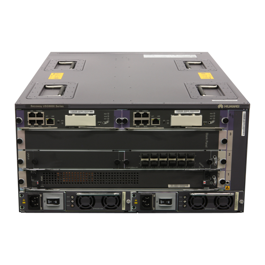
- Page 76 EPW30B-48A AC power module. Both the 1600 W AC PDB and EPW30B-48A AC power module are hot-swappable. Figure 1-39 shows the AC PDB and its panel. Figure 1-39 EPW30B-48A AC power module -4 8 ALARM ALARM FAULT FAULT EPW30B-48A Issue 03 (2017-12-15) Huawei Proprietary and Confidential Copyright © Huawei Technologies Co., Ltd.
- Page 77 220 V rated voltage: 200 V AC to 240 V AC, 50/60 Hz l 110 V rated voltage: 100 V AC to 120 V AC, 50/60 Hz Issue 03 (2017-12-15) Huawei Proprietary and Confidential Copyright © Huawei Technologies Co., Ltd.
-
Page 78: Heat Dissipation System
The system draws in air for heat dissipation in the DC and AC chassis, as shown in Figure 1-40 Figure 1-41, respectively. Figure 1-40 Air flow in the USG9520 DC chassis Cool air Hot air Issue 03 (2017-12-15) Huawei Proprietary and Confidential Copyright © Huawei Technologies Co., Ltd. -
Page 79: Fan Module
96 hours and the accumulated operation time of the system per year does not exceed 15 days. Issue 03 (2017-12-15) Huawei Proprietary and Confidential Copyright © Huawei Technologies Co., Ltd. - Page 80 160 mm x 108 mm x 213 mm depth x height) Weight 1.5 kg Maximum wind pressure 700 Pa Maximum wind rate 850 m Maximum noise 78 dB Issue 03 (2017-12-15) Huawei Proprietary and Confidential Copyright © Huawei Technologies Co., Ltd.
-
Page 81: Air Filter
The air filter of the USG9520 is located on the left rear of the chassis, as shown in Figure 1-43. Figure 1-43 Air filter on the USG9520 air intake frame Issue 03 (2017-12-15) Huawei Proprietary and Confidential Copyright © Huawei Technologies Co., Ltd. -
Page 82: Control Plane
The two MPUs work in 1:1 backup mode. Each MPU monitors the status of the other. If the active MPU is faulty, the standby MPU automatically takes over as the active MPU. Issue 03 (2017-12-15) Huawei Proprietary and Confidential Copyright © Huawei Technologies Co., Ltd. -
Page 83: Technical Specifications
AC chassis: 40.7 kg (maximum) Power specifications Power supply Double hot-swappable power modules mode Double hot-swappable power modules Rated input -48 V DC to -60 V DC voltage range Issue 03 (2017-12-15) Huawei Proprietary and Confidential Copyright © Huawei Technologies Co., Ltd. - Page 84 5% RH to 85% RH, no coagulation relative Short-term 5% RH to 95% RH, no coagulation humidity Storage relative humidity 0% RH to 95% RH Long-term altitude Lower than 3000 m Issue 03 (2017-12-15) Huawei Proprietary and Confidential Copyright © Huawei Technologies Co., Ltd.
-
Page 85: Boards
The USG9500 LPU uses either an FPIC or integrated board structure and provides network interfaces externally. Table 1-35, Table 1-36, and Table 1-37 show USG9500 board mappings. Issue 03 (2017-12-15) Huawei Proprietary and Confidential Copyright © Huawei Technologies Co., Ltd. - Page 86 E8KE-X8- V300R00 SRUA-200 1C01 E8KE-X3- V500R00 1C00 V300R00 MPUD 1C01 E8KE-X16- V300R00 SFUC-200SP 1C01 E8KE-X8- V300R00 SFUC-200 1C01 SPC-20- O-E8KE SPC- V300R00 SPU-X3-B APPSEC- 1C01 SPC- IPS-20 Issue 03 (2017-12-15) Huawei Proprietary and Confidential Copyright © Huawei Technologies Co., Ltd.
- Page 87 V500R00 SPU-X3-B2 O-H&M 1C50 SPCB-20- O-H&M SPCA- APPSEC- SPCB- APPSEC- SPC-20- O-E8KE SPC- APPSEC- SPC- IPS-20 SPCA-20- SPU-X8X16- V300R00 O-H&M 1C01 SPCB-20- O-H&M SPCA- APPSEC- SPCB- APPSEC- Issue 03 (2017-12-15) Huawei Proprietary and Confidential Copyright © Huawei Technologies Co., Ltd.
- Page 88 SPC- IPS-20 SPUA-20-O- V500R00 1C50 SPUB-20-O- V500R00 1C50 SPC-20- O-E8KE SPC- APPSEC- SPC- IPS-20 SPU- SPCA-20- V300R00 X8X16-20-O- O-H&M 1C01 E8KE SPCB-20- O-H&M SPCA- APPSEC- SPCB- APPSEC- Issue 03 (2017-12-15) Huawei Proprietary and Confidential Copyright © Huawei Technologies Co., Ltd.
- Page 89 SPUA-20-O- V500R00 O-H&M 1C50 SPCB-20- O-H&M SPCA- APPSEC- SPCB- APPSEC- SPC-20- O-E8KE SPC- APPSEC- SPC- IPS-20 SPCA-20- SPUB-20-O- V500R00 O-H&M 1C50 SPCB-20- O-H&M SPCA- APPSEC- SPCB- APPSEC- Issue 03 (2017-12-15) Huawei Proprietary and Confidential Copyright © Huawei Technologies Co., Ltd.
- Page 90 + FPIC A Card 1C00 (E8KE- X-101-5X 10GE- SFP+) 1.4.5.5 6*10GE SFP+ Daughter Card (FW-6X10 G-SFP+) 1.4.5.6 12*10GE SFP+ Daughter Card (FW-12X1 0G-SFP+) 1.4.5.7 3- Port 40GBase Issue 03 (2017-12-15) Huawei Proprietary and Confidential Copyright © Huawei Technologies Co., Ltd.
- Page 91 Subcard appabl Supporti ng the Board QSFP+ FPIC (FW-3X40 G-QSFP 1.4.5.8 1- Port 40GBase LAN-CFP FPIC A (E8KE- X-101-1X 40GE- CFP) 1.4.5.9 1*100GE Daughter Card (FW-1X10 0G-CFP) Issue 03 (2017-12-15) Huawei Proprietary and Confidential Copyright © Huawei Technologies Co., Ltd.
- Page 92 V500R00 LPUF-120 + FPIC A 1C00 (E8KE- X-101-5X 10GE- SFP+) 1.4.6.5 6*10GE SFP+ Daughter Card (FW-6X10 GE-SFP+) 1.4.6.6 12*10GE SFP+ Daughter Card (FW-12X1 0GE-SFP 1.4.6.7 3- Port Issue 03 (2017-12-15) Huawei Proprietary and Confidential Copyright © Huawei Technologies Co., Ltd.
- Page 93 Supporti ng the Board 40GBase QSFP+ FPIC (FW-3X40 G-QSFP 1.4.6.8 1- Port 40GBase LAN-CFP FPIC A (E8KE- X-101-1X 40GE- CFP) 1.4.6.9 1*100GE Daughter Card (FW-1X10 0GE- CFP) Issue 03 (2017-12-15) Huawei Proprietary and Confidential Copyright © Huawei Technologies Co., Ltd.
- Page 94 V300R00 LPUF-101 1.4.7.4 5- 1C01 Port 10GBase LAN/ WAN-SFP + FPIC A (E8KE- X-101-5X 10GE- SFP+) 1.4.7.5 1- Port 40GBase LAN-CFP FPIC A (E8KE- X-101-1X 40GE- CFP) Issue 03 (2017-12-15) Huawei Proprietary and Confidential Copyright © Huawei Technologies Co., Ltd.
- Page 95 1.4.8.3 2- Port 10GBase LAN/ WAN- Flexible V300R00 LPUF-40-A Card 1C01 (P40-2x10 GBase LAN/ WAN- XFP) 1.4.8.4 4- port 10GBase LAN/ WAN- FPIC (P40-4x10 GBase LAN/ WAN- XFP) Issue 03 (2017-12-15) Huawei Proprietary and Confidential Copyright © Huawei Technologies Co., Ltd.
- Page 96 1.4.9.4 1- port OC-192c/ STM-64c POS-XFP FPIC (1 x OC-192c/ STM-64c POS- XFP) 1.4.9.5 1- port 10GBase LAN/ WAN- FPIC (1 x 10GBase LAN/ WAN) 1.4.9.6 4- Port Issue 03 (2017-12-15) Huawei Proprietary and Confidential Copyright © Huawei Technologies Co., Ltd.
- Page 97 1 Hardware Overview First Software Hotsw Version Board Name Subcard appabl Supporti ng the Board 10GBase WAN/ LAN-XFP FPIC (4x10GBa se LAN/ WAN) Integ V300R00 rated LPUI-101 1C01 Issue 03 (2017-12-15) Huawei Proprietary and Confidential Copyright © Huawei Technologies Co., Ltd.
- Page 98 1 Hardware Overview Table 1-36 Mappings between SPUs and cards SPU Mother Board SPU- SPU- X8X1 X3-2 SPU Card 6-20- 0-O- -X3- -X3- SPC-20-O- E8KE SPC- APPSEC- Issue 03 (2017-12-15) Huawei Proprietary and Confidential Copyright © Huawei Technologies Co., Ltd.
- Page 99 HUAWEI USG9500 Series Hardware Guide 1 Hardware Overview SPU Mother Board SPU- SPU- X8X1 X3-2 SPU Card 6-20- 0-O- -X3- -X3- SPC- IPS-20 SPCA-20- O-H&M Issue 03 (2017-12-15) Huawei Proprietary and Confidential Copyright © Huawei Technologies Co., Ltd.
- Page 100 HUAWEI USG9500 Series Hardware Guide 1 Hardware Overview SPU Mother Board SPU- SPU- X8X1 X3-2 SPU Card 6-20- 0-O- -X3- -X3- SPCB-20- O-H&M SPCA- APPSEC- Issue 03 (2017-12-15) Huawei Proprietary and Confidential Copyright © Huawei Technologies Co., Ltd.
- Page 101 HUAWEI USG9500 Series Hardware Guide 1 Hardware Overview SPU Mother Board SPU- SPU- X8X1 X3-2 SPU Card 6-20- 0-O- -X3- -X3- SPCB- APPSEC- Issue 03 (2017-12-15) Huawei Proprietary and Confidential Copyright © Huawei Technologies Co., Ltd.
- Page 102 X-SFP FPIC (12x100/1000 Base-SFP) 1.4.8.2 20- Port 100/1000Base V300 030566 -X-SFP R001 Flexible Card (P40-20xGE/ FE-SFP) 1.4.7.2 24- Port 100/1000 V300 Base-X-SFP 030566 R001 FPIC (E8KE- X-101-24XG E-SFP) Issue 03 (2017-12-15) Huawei Proprietary and Confidential Copyright © Huawei Technologies Co., Ltd.
- Page 103 LAN/ WAN-XFP) 1.4.9.6 4-Port 10GBase V300 WAN/LAN- 0305G0 R001 XFP FPIC (4x10GBase LAN/WAN) 1.4.7.3 4-Port 10G Base V300 LAN -SFP+ 0305G0 R001 FPIC (E8KE- X-101-4X10G E-SFP+) Issue 03 (2017-12-15) Huawei Proprietary and Confidential Copyright © Huawei Technologies Co., Ltd.
- Page 104 V300 030566 FPIC A R001 (E8KE- X-101-1X40G E-CFP) 1.4.5.9 030566 1*100GE V500 Daughter R001 Card (FW-1X100G -CFP) 1.4.5.7 3-Port 40GBase V500 030568 QSFP+ FPIC R001 (FW-3X40G- QSFP+) Issue 03 (2017-12-15) Huawei Proprietary and Confidential Copyright © Huawei Technologies Co., Ltd.
-
Page 105: Board Structure
Figure 1-44. Figure 1-44 Structure of the integrated board 1. Ejector lever 2. Captive screw 3. Connector 4. Bolt Issue 03 (2017-12-15) Huawei Proprietary and Confidential Copyright © Huawei Technologies Co., Ltd. - Page 106 Figure 1-46. Figure 1-46 Structure of the flexible subcard 1. Circuit board 2. Captive screw 3. Connector 4. Heat sinks Issue 03 (2017-12-15) Huawei Proprietary and Confidential Copyright © Huawei Technologies Co., Ltd.
-
Page 107: Rules For Numbering Slots And Interfaces
For cards with subcards, if a card has both half-width and one-quarter-width subcards, such as LPUF-101, the subcard slot number depends on the type of inserted subcards, as shown in Figure 1-50. Issue 03 (2017-12-15) Huawei Proprietary and Confidential Copyright © Huawei Technologies Co., Ltd. - Page 108 For example, on the USG9560, the LPU slot number is 7, the FPIC slot number is 1, and the interface number is 2. Therefore, the interface is named 7/1/2. NOTE If the LPU is a fixed interface board, the FPIC slot number is considered 0. Issue 03 (2017-12-15) Huawei Proprietary and Confidential Copyright © Huawei Technologies Co., Ltd.
-
Page 109: Mpus And Srus
Off: The system is working properly. ACT active/standby l Steady on: The MPU is in the active state. indicator (green) l Off: The MPU is in the standby state. Issue 03 (2017-12-15) Huawei Proprietary and Confidential Copyright © Huawei Technologies Co., Ltd. - Page 110 It connects to the Modem for remote maintenance through dialing. Others USB interface It is not used and reserved. CLK/TOD0 They are reserved to input or output clock signals. CLK/TOD1 CLK/1PPS Issue 03 (2017-12-15) Huawei Proprietary and Confidential Copyright © Huawei Technologies Co., Ltd.
- Page 111 Table 1-40 lists the console interface attributes. Table 1-40 Console interface attributes Attribute Description Connector type RJ45 Operation mode Duplex Universal Asynchronous Receiver/Transmitter (UART) Electrical attribute RS-232 Issue 03 (2017-12-15) Huawei Proprietary and Confidential Copyright © Huawei Technologies Co., Ltd.
- Page 112 Typical power 85 W consumption Maximum power 95 W consumption Typical heat 290 BTU/hour consumption Maximum heat 324.2 BTU/hour consumption Board weight 4.2 kg Issue 03 (2017-12-15) Huawei Proprietary and Confidential Copyright © Huawei Technologies Co., Ltd.
-
Page 113: E8Ke-X8-Srua-200
Off: The SRU is in the standby state. RESET button The button is used for resetting the SRU. If you press the RESET button, the SRU resets. CF card slot, button, and indicator Issue 03 (2017-12-15) Huawei Proprietary and Confidential Copyright © Huawei Technologies Co., Ltd. - Page 114 It connects to the Modem for remote maintenance through dialing. Others USB interface It is not used and reserved. CLK/TOD0 They are reserved to input or output clock signals. CLK/TOD1 CLK/1PPS CLK/Serial Issue 03 (2017-12-15) Huawei Proprietary and Confidential Copyright © Huawei Technologies Co., Ltd.
- Page 115 Duplex Universal Asynchronous Receiver/Transmitter (UART) Electrical attribute RS-232 Baud rate 9600 bit/s (default value), adjustable Data equipment type Data Circuit-terminating Equipment (DCE) Cable specification 8-core shielded cable Issue 03 (2017-12-15) Huawei Proprietary and Confidential Copyright © Huawei Technologies Co., Ltd.
-
Page 116: E8Ke-X3-Mpu
Maximum heat 545.9 BTU/hour consumption Board weight 4.8 kg 1.4.2.3 E8KE-X3-MPU E8KE-X3-MPU is the USG9520 MPU. It is hot-swappable. Panel Figure 1-54 shows the appearance of the E8KE-X3-MPU. Issue 03 (2017-12-15) Huawei Proprietary and Confidential Copyright © Huawei Technologies Co., Ltd. - Page 117 Off: The link is Down. Ethernet network interfaces) MGMT-ETH ACT l Blinking: Data is being transmitted. indicator (amber) (on l Off: No data is being transmitted. Ethernet interfaces) Issue 03 (2017-12-15) Huawei Proprietary and Confidential Copyright © Huawei Technologies Co., Ltd.
- Page 118 Electrical attribute RS-232 Baud rate 9600 bit/s (default value), which can be changed as required Data equipment type Data Circuit-terminating Equipment (DCE) Cable specification 8-core shielded cable Issue 03 (2017-12-15) Huawei Proprietary and Confidential Copyright © Huawei Technologies Co., Ltd.
-
Page 119: Mpud
Maximum heat 120.1 BTU/hour consumption Board weight 1.7 kg 1.4.2.4 MPUD MPUD is the USG9520 MPU and is hot-swappable. MPUD Panel Figure 1-55 shows the MPUD panel. Issue 03 (2017-12-15) Huawei Proprietary and Confidential Copyright © Huawei Technologies Co., Ltd. - Page 120 If the indicator is on, the MPUD is in the active state. indicator (green) If the indicator is off, the MPUD is in the standby state. RESET button Press this button to reset the MPUD. Issue 03 (2017-12-15) Huawei Proprietary and Confidential Copyright © Huawei Technologies Co., Ltd.
- Page 121 10Base-T/100Base-TX/1000Base-T-RJ45 interfaces. Table 1-54 10Base-T/100Base-TX/1000Base-T-RJ45 interface attributes Attribute Description Connector type RJ45 Operation mode 10M/100M/1000M auto-sensing interfaces, supporting full- duplex mode Standards compliance IEEE 802.3-2002 Issue 03 (2017-12-15) Huawei Proprietary and Confidential Copyright © Huawei Technologies Co., Ltd.
- Page 122 9600 bit/s (default value), adjustable Data equipment type Data Terminal Equipment (DTE) Cable specification 8-core shielded cable Technical Specifications Table 1-57 lists the technical specifications of the MPUD. Issue 03 (2017-12-15) Huawei Proprietary and Confidential Copyright © Huawei Technologies Co., Ltd.
-
Page 123: Sfus
E8KE-X16-SFUC-200SP is the USG9580 SFU. It uses non-blocking switch fabric, is hot- swappable, and is responsible for data switching of the entire system. Panel Figure 1-56 shows the E8KE-X16-SFUC-200SP. Figure 1-56 E8KE-X16-SFUC-200SP Issue 03 (2017-12-15) Huawei Proprietary and Confidential Copyright © Huawei Technologies Co., Ltd. -
Page 124: E8Ke-X8-Sfuc-200
4.26 kg 1.4.3.2 E8KE-X8-SFUC-200 E8KE-X8-SFUC-200 is the USG9560 SFU. It uses non-blocking switch fabric, is hot- swappable, and is responsible for data switching of the entire system. Issue 03 (2017-12-15) Huawei Proprietary and Confidential Copyright © Huawei Technologies Co., Ltd. - Page 125 Table 1-59 Technical specifications of the E8KE-X8-SFUC-200 Item Specifications Specifications SFUI-200-C Dimensions (width x 400 mm x 553.5 mm x 35 mm depth x height) Typical power 77 W consumption Issue 03 (2017-12-15) Huawei Proprietary and Confidential Copyright © Huawei Technologies Co., Ltd.
-
Page 126: Spus And Spcs
To remove a board, press and hold the button for six seconds until the OFL indicator turns on. OFL indicator (red) Steady on: You can remove the board. Issue 03 (2017-12-15) Huawei Proprietary and Confidential Copyright © Huawei Technologies Co., Ltd. -
Page 127: X3 Spu (Spu-X3-B2)
It has one available slot that can house a firewall SPC or application security SPC. The SPU-X3-B2 is inserted into the LPU/SPU slot of the USG9520. Issue 03 (2017-12-15) Huawei Proprietary and Confidential Copyright © Huawei Technologies Co., Ltd. - Page 128 Board silkscreen name SPUE SPU-X3-B2 Dimensions (width x 400 mm x 520 mm x 41 mm depth x height) Typical power 80 W consumption Maximum power 100 W consumption Issue 03 (2017-12-15) Huawei Proprietary and Confidential Copyright © Huawei Technologies Co., Ltd.
-
Page 129: X8&X16 Spu (Spu-X8X16-B)
To remove a board, press and hold the button for six seconds until the OFL indicator turns on. OFL indicator (red) Steady on: You can remove the board. Issue 03 (2017-12-15) Huawei Proprietary and Confidential Copyright © Huawei Technologies Co., Ltd. -
Page 130: Firewall Service Processing Unit (Spu-X3-20-O-E8Ke, For Usg9520)
1.4.4.4 Firewall Service Processing Unit (SPU-X3-20-O-E8KE, for USG9520) The SPU-X3-20-O-E8KE is inserted into the LPU/SPU slot of the USG9520, has an expansion slot, and is hot-swappable. Panel Figure 1-61 shows the SPU-X3-20-O-E8KE. Issue 03 (2017-12-15) Huawei Proprietary and Confidential Copyright © Huawei Technologies Co., Ltd. - Page 131 If the indicator turns red for one second and then turns off, you can safely remove the SPC. Interface Attributes The SPU-X3-20-O-E8KE does not have external interfaces. Technical Specifications Table 1-63 lists the technical specifications of the SPU-X3-20-O-E8KE. Issue 03 (2017-12-15) Huawei Proprietary and Confidential Copyright © Huawei Technologies Co., Ltd.
-
Page 132: Firewall Service Processing Unit (Spua-20-O-M, For Usg9520)
The SPUA-20-O-M is inserted into the LPU/SPU slot of the USG9520, has no expansion slot, and is hot-swappable. Panel Figure 1-62 shows the SPUA-20-O-M. Figure 1-62 SPUA-20-O-M ! NOT SWAP Issue 03 (2017-12-15) Huawei Proprietary and Confidential Copyright © Huawei Technologies Co., Ltd. - Page 133 Table 1-64 Technical specifications of the SPUA-20-O-M Item Specifications Board silkscreen name SPUE SPUA-20-O-M Dimensions (width x 400 mm x 520 mm x 41 mm depth x height) Typical power 180 W consumption Issue 03 (2017-12-15) Huawei Proprietary and Confidential Copyright © Huawei Technologies Co., Ltd.
-
Page 134: Firewall Service Processing Unit (Spub-20-O-M, For Usg9520)
To remove an SPU, press and hold the OFL button for six seconds until the OFL indicator turns on. OFL indicator (red) Steady on: You can remove the SPU. Issue 03 (2017-12-15) Huawei Proprietary and Confidential Copyright © Huawei Technologies Co., Ltd. - Page 135 Dimensions (width x 400 mm x 520 mm x 41 mm depth x height) Typical power 280 W consumption Maximum power 300 W consumption Typical heat 955.4 BTU/hour consumption Issue 03 (2017-12-15) Huawei Proprietary and Confidential Copyright © Huawei Technologies Co., Ltd.
-
Page 136: Firewall Service Processing Unit (Spu-X8X16-20-O-E8Ke, For Usg9560/Usg9580)
Blinks every 2 seconds (0.5 Hz): The SPU is running normally. l Blinks four times every second (4 Hz): The SPU is in the alarm state or starting but not registered. Issue 03 (2017-12-15) Huawei Proprietary and Confidential Copyright © Huawei Technologies Co., Ltd. - Page 137 311.9 W consumption Typical heat 969 BTU/hour consumption Maximum heat 1064.2 BTU/hour consumption Board weight 6.96 kg Maximum input voltage -72 V to -38 V range (DC) Issue 03 (2017-12-15) Huawei Proprietary and Confidential Copyright © Huawei Technologies Co., Ltd.
-
Page 138: Firewall Service Processing Unit (Spua-20-O-H, For Usg9560/Usg9580)
OFL button To remove an SPC, press and hold the OFL button for six seconds until the OFL indicator turns red for one second and then turns off. Issue 03 (2017-12-15) Huawei Proprietary and Confidential Copyright © Huawei Technologies Co., Ltd. - Page 139 Maximum heat 801.9 BTU/hour consumption Board weight 6.64 kg Maximum input voltage -72 V to -38 V range (DC) CPU number 1.6 GHz Memory DDR4 32GB Issue 03 (2017-12-15) Huawei Proprietary and Confidential Copyright © Huawei Technologies Co., Ltd.
-
Page 140: Firewall Service Processing Unit (Spub-20-O-H, For Usg9560/Usg9580)
(4 Hz), the SPC is in the alarm state or starting but not registered. l If the indicator turns red for one second and then turns off, you can safely remove the SPC. Issue 03 (2017-12-15) Huawei Proprietary and Confidential Copyright © Huawei Technologies Co., Ltd. -
Page 141: Firewall Performance Expansion Card (Spc-20-O-E8Ke)
The SPC-20-O-E8KE is a dual-CPU service sub-card of the firewall service board, can be inserted into an SPU slot, and is hot-swappable. Panel Figure 1-67 shows the SPC-20-O-E8KE. Figure 1-67 SPC-20-O-E8KE SPC-20-O-E8KE SPC-20-O-E8KE SPCB02 SPCB02 Issue 03 (2017-12-15) Huawei Proprietary and Confidential Copyright © Huawei Technologies Co., Ltd. - Page 142 Maximum power 174.9 W consumption Typical heat 542.5 BTU/hour consumption Maximum heat 596.8 BTU/hour consumption Board weight 1.62 kg CPU number 1.2 GHz Memory DDR3 16 GB/CPU Issue 03 (2017-12-15) Huawei Proprietary and Confidential Copyright © Huawei Technologies Co., Ltd.
-
Page 143: Firewall Performance Expansion Card (Spca-20-O-H&M)
Table 1-70 Technical specifications of the SPCA-20-O-H&M Item Specifications Board silkscreen name SPCF01 SPCA-20-O-H&M Dimensions (width x 175 mm x 280 mm x 36 mm depth x height) Issue 03 (2017-12-15) Huawei Proprietary and Confidential Copyright © Huawei Technologies Co., Ltd. -
Page 144: Firewall Performance Expansion Card (Spcb-20-O-H&M)
OFL button To remove a board, press and hold the OFL button for six seconds until the OFL indicator turns red for one second and then turns off. Issue 03 (2017-12-15) Huawei Proprietary and Confidential Copyright © Huawei Technologies Co., Ltd. -
Page 145: Application Security Service Processing Card (Spc-Appsec-Fw)
The SPC-APPSEC-FW is a dual-CPU subcard for processing application security services and has an IAE to provide content security. This subcard takes up a slot on the motherboard. Issue 03 (2017-12-15) Huawei Proprietary and Confidential Copyright © Huawei Technologies Co., Ltd. - Page 146 Table 1-72 Technical specifications of the SPC-APPSEC-FW Item Specifications Board silkscreen name SPC-APPSEC-FW Dimensions (width x 175 mm x 280 mm x 36 mm depth x height) Typical power 159 W consumption Issue 03 (2017-12-15) Huawei Proprietary and Confidential Copyright © Huawei Technologies Co., Ltd.
-
Page 147: Application Security Service Processing Card (Spc-Ips-20)
OFL button To remove a board, press and hold the OFL button for six seconds until the OFL indicator turns red for one second and then turns off. Issue 03 (2017-12-15) Huawei Proprietary and Confidential Copyright © Huawei Technologies Co., Ltd. - Page 148 Maximum power 174.9 W consumption Typical heat 542.5 BTU/hour consumption Maximum heat 596.8 BTU/hour consumption Board weight 1.8 kg CPU number 1.2 GHz Memory DDR3 16 GB/CPU Issue 03 (2017-12-15) Huawei Proprietary and Confidential Copyright © Huawei Technologies Co., Ltd.
-
Page 149: Enhanced Application Security Service Processing Card A (Spca-Appsec-Fw)
The SPCA-APPSEC-FW does not have external interfaces. Technical Specifications Table 1-74 lists the technical specifications of the SPCA-APPSEC-FW. Table 1-74 Technical specifications of the SPCA-APPSEC-FW Item Specifications Board silkscreen name SPCF01 SPCA-APPSEC-FW Issue 03 (2017-12-15) Huawei Proprietary and Confidential Copyright © Huawei Technologies Co., Ltd. -
Page 150: Enhanced Application Security Service Processing Card B (Spcb-Appsec-Fw)
OFL button To remove a board, press and hold the OFL button for six seconds until the OFL indicator turns red for one second and then turns off. Issue 03 (2017-12-15) Huawei Proprietary and Confidential Copyright © Huawei Technologies Co., Ltd. - Page 151 Maximum power 200 W consumption Typical heat 614.2 BTU/hour consumption Maximum heat 682.4 BTU/hour consumption Board weight 1.42 kg CPU number 1.6 GHz Memory DDR4 32 GB/CPU Issue 03 (2017-12-15) Huawei Proprietary and Confidential Copyright © Huawei Technologies Co., Ltd.
-
Page 152: Lpuf-240 And Fpics
Blinks every 2 seconds (0.5 Hz): The system is working properly. l Blinks twice each second (2 Hz): The system is in the alarm state. Interface Attributes The LPUF-240 does not have external interfaces. Issue 03 (2017-12-15) Huawei Proprietary and Confidential Copyright © Huawei Technologies Co., Ltd. -
Page 153: 20-Port 10/100/1000Base-Rj45 Fpic (Fw-20X1G-Rj45)
The FW-20X1G-RJ45 occupies one 1/2-width flexible card slot, is compatible with LPUF-240s, and LPUF-120s, but is not hot-swappable. Panel Figure 1-75 shows the FW-20X1G-RJ45. Figure 1-75 20-port 10/100/1000Base-RJ45 FPIC panel FW-20X1G-RJ45 Issue 03 (2017-12-15) Huawei Proprietary and Confidential Copyright © Huawei Technologies Co., Ltd. - Page 154 Silk-screen board name FW-20X1G-RJ45 Dimensions (width x 178 mm x 225 mm x 38 mm depth x height) Typical power 31 W consumption Maximum power 34.1 W consumption Issue 03 (2017-12-15) Huawei Proprietary and Confidential Copyright © Huawei Technologies Co., Ltd.
-
Page 155: 24-Port 100/1000 Base-X-Sfp Fpic (E8Ke-X-101-24Xge-Sfp)
Indicator below the l Steady on: The link is connected. interface (green) l Blinking: Data is being transmitted or received. l Off: The link is disconnected. Issue 03 (2017-12-15) Huawei Proprietary and Confidential Copyright © Huawei Technologies Co., Ltd. - Page 156 Typical power 37 W consumption Maximum power 40.7 W consumption Typical heat 126.2 BTU/hour consumption Maximum heat 138.9 BTU/hour consumption Board weight 0.9 kg Issue 03 (2017-12-15) Huawei Proprietary and Confidential Copyright © Huawei Technologies Co., Ltd.
-
Page 157: 5-Port 10Gbase Lan/Wan-Sfp+ Fpic A (E8Ke-X-101-5X10Ge-Sfp+)
Off: The link is disconnected. Interface Attributes Table 1-81 lists the attributes of interfaces on the E8KE-X-101-5X10GE-SFP+. Table 1-81 E8KE-X-101-5X10GE-SFP+ interface attributes Attribute Description Connector type LC/PC Issue 03 (2017-12-15) Huawei Proprietary and Confidential Copyright © Huawei Technologies Co., Ltd. - Page 158 Typical power 29 W consumption Maximum power 31.9 W consumption Typical heat 99 BTU/hour consumption Maximum heat 108.8 BTU/hour consumption Board weight 0.9 kg Issue 03 (2017-12-15) Huawei Proprietary and Confidential Copyright © Huawei Technologies Co., Ltd.
-
Page 159: 10Ge Sfp+ Daughter Card (Fw-6X10G-Sfp+)
Off: The link is disconnected. Interface Attributes Table 1-83 lists the attributes of interfaces on the FW-6X10G-SFP+. Table 1-83 FW-6X10G-SFP+ interface attributes Attribute Description Connector type LC/PC Issue 03 (2017-12-15) Huawei Proprietary and Confidential Copyright © Huawei Technologies Co., Ltd. - Page 160 Typical power 34 W consumption Maximum power 37.4 W consumption Typical heat 116 BTU/hour consumption Maximum heat 127.6 BTU/hour consumption Board weight 0.65 kg Issue 03 (2017-12-15) Huawei Proprietary and Confidential Copyright © Huawei Technologies Co., Ltd.
-
Page 161: 10Ge Sfp+ Daughter Card (Fw-12X10G-Sfp+)
Off: The link is disconnected. Interface Attributes Table 1-85 lists the attributes of interfaces on the FW-12X10G-SFP+. Table 1-85 FW-12X10G-SFP+ interface attributes Attribute Description Connector type LC/PC Issue 03 (2017-12-15) Huawei Proprietary and Confidential Copyright © Huawei Technologies Co., Ltd. - Page 162 Typical power 52 W consumption Maximum power 57.2 W consumption Typical heat 177.4 BTU/hour consumption Maximum heat 195.2 BTU/hour consumption Board weight 0.75 kg Issue 03 (2017-12-15) Huawei Proprietary and Confidential Copyright © Huawei Technologies Co., Ltd.
-
Page 163: 3-Port 40Gbase Qsfp+ Fpic (Fw-3X40G-Qsfp+)
1.5.6 40 Gbit/s QSFP+ Optical Module. Working mode Full-duplex Standards IEEE 802.3-2002 compliance Frame format Ethernet_II, Ethernet_SAP, and Ethernet_SNAP Issue 03 (2017-12-15) Huawei Proprietary and Confidential Copyright © Huawei Technologies Co., Ltd. -
Page 164: 1-Port 40Gbase Lan-Cfp Fpic A (E8Ke-X-101-1X40Ge-Cfp)
LPUF-240s, LPUF-120s and LPUF-101s, works in LAN mode, uses CFP optical modules, but is not hot-swappable. Panel Figure 1-81 shows the E8KE-X-101-1X40GE-CFP. Figure 1-81 E8KE-X-101-1X40GE-CFP E8KE-X-101-1X40GE-CFP E8KE-X-101-1X40GE-CFP Issue 03 (2017-12-15) Huawei Proprietary and Confidential Copyright © Huawei Technologies Co., Ltd. - Page 165 Board silkscreen name E8KE-X-101-1X40GE-CFP Dimensions (width x 178 mm x 225 mm x 38 mm depth x height) Typical power 28 W consumption Maximum power 30.8 W consumption Issue 03 (2017-12-15) Huawei Proprietary and Confidential Copyright © Huawei Technologies Co., Ltd.
-
Page 166: 100Ge Cfp Daughter Card (Fw-1X100G-Cfp)
L/A (green) l Blinking: Data is being transmitted or received. l Off: The link is disconnected. Interface Attributes Table 1-91 lists the attributes of interfaces on the FW-1X100G-CFP. Issue 03 (2017-12-15) Huawei Proprietary and Confidential Copyright © Huawei Technologies Co., Ltd. -
Page 167: Lpuf-120 And Fpics
The flexible LPU comprises the motherboard (LPUF-120) and multiple flexible cards (subcards), improving networking flexibility. The flexible LPU supports 120G line-rate forwarding, which reduces costs and provides customized solutions for users. Issue 03 (2017-12-15) Huawei Proprietary and Confidential Copyright © Huawei Technologies Co., Ltd. -
Page 168: Lpuf-120
Blinks twice each second (2 Hz): The system is in the alarm state. Interface Attributes The LPUF-120 does not have external interfaces. Technical Specifications Table 1-93 lists the technical specifications of the LPUF-120. Issue 03 (2017-12-15) Huawei Proprietary and Confidential Copyright © Huawei Technologies Co., Ltd. -
Page 169: 20-Port 10/100/1000Base-Rj45 Fpic (Fw-20X1G-Rj45)
STATUS (green) l Blinks every 2 seconds (0.5 Hz): The system is running normally. l Blinks twice each second (2 Hz): The system is in the alarm state. Issue 03 (2017-12-15) Huawei Proprietary and Confidential Copyright © Huawei Technologies Co., Ltd. - Page 170 178 mm x 225 mm x 38 mm depth x height) Typical power 31 W consumption Maximum power 34.1 W consumption Typical heat 105.8 BTU/hour consumption Maximum heat 116.4 BTU/hour consumption Issue 03 (2017-12-15) Huawei Proprietary and Confidential Copyright © Huawei Technologies Co., Ltd.
-
Page 171: 24-Port 100/1000 Base-X-Sfp Fpic (E8Ke-X-101-24Xge-Sfp)
(green) l Blinking: Data is being transmitted or received. l Off: The link is disconnected. Interface Attributes Table 1-96 lists the attributes of interfaces on the E8KE-X-101-24XGE-SFP. Issue 03 (2017-12-15) Huawei Proprietary and Confidential Copyright © Huawei Technologies Co., Ltd. -
Page 172: 5-Port 10Gbase Lan/Wan-Sfp+ Fpic A (E8Ke-X-101-5X10Ge-Sfp+)
The E8KE-X-101-5X10GE-SFP+ occupies one 1/2-width flexible card slot, is compatible with LPUF-240s, LPUF-120s, and LPUF-101s, works in LAN or WAN mode, uses SFP+ optical modules, but is not hot-swappable. Issue 03 (2017-12-15) Huawei Proprietary and Confidential Copyright © Huawei Technologies Co., Ltd. - Page 173 To use 1.5.1 1 Gbit/s Electrical Transceiver 1.5.2 1.25 Gbit/s SFP/eSFP Optical Module in earlier versions, you need to upgrade the software version. Working mode Full-duplex Issue 03 (2017-12-15) Huawei Proprietary and Confidential Copyright © Huawei Technologies Co., Ltd.
-
Page 174: 10Ge Sfp+ Daughter Card (Fw-6X10Ge-Sfp+)
LPUF-240s and LPUF-120s, works in LAN or WAN mode, uses SFP+ optical modules, but is not hot-swappable. Panel Figure 1-87 shows the FW-6X10G-SFP+. Figure 1-87 FW-6X10G-SFP+ FW-6X10G-SFP+ Issue 03 (2017-12-15) Huawei Proprietary and Confidential Copyright © Huawei Technologies Co., Ltd. - Page 175 Working mode Full-duplex Frame format Ethernet_II, Ethernet_SAP, and Ethernet_SNAP Network protocol Technical Specifications Table 1-101 lists the technical specifications of the FW-6X10G-SFP+. Issue 03 (2017-12-15) Huawei Proprietary and Confidential Copyright © Huawei Technologies Co., Ltd.
-
Page 176: 10Ge Sfp+ Daughter Card (Fw-12X10Ge-Sfp+)
Indicator below the l Steady on: The link is connected. interface (green) l Blinking: Data is being transmitted or received. l Off: The link is disconnected. Issue 03 (2017-12-15) Huawei Proprietary and Confidential Copyright © Huawei Technologies Co., Ltd. - Page 177 Board silkscreen name FW-12X10G-SFP+ Dimensions (width x 193 mm x 178.65 mm x 37.2 mm depth x height) Typical power 52 W consumption Maximum power 57.2 W consumption Issue 03 (2017-12-15) Huawei Proprietary and Confidential Copyright © Huawei Technologies Co., Ltd.
-
Page 178: 3-Port 40Gbase Qsfp+ Fpic (Fw-3X40G-Qsfp+)
Steady on: The link is connected. l Blinking: Data is being transmitted or received. l Off: The link is disconnected. Interface Attributes Table 1-104 lists the attributes of interfaces on FW-3X40G-QSFP+. Issue 03 (2017-12-15) Huawei Proprietary and Confidential Copyright © Huawei Technologies Co., Ltd. -
Page 179: 1-Port 40Gbase Lan-Cfp Fpic A (E8Ke-X-101-1X40Ge-Cfp)
The E8KE-X-101-1X40GE-CFP occupies one 1/2-width flexible card slot, is compatible with LPUF-240s, LPUF-120s and LPUF-101s, works in LAN mode, uses CFP optical modules, but is not hot-swappable. Issue 03 (2017-12-15) Huawei Proprietary and Confidential Copyright © Huawei Technologies Co., Ltd. - Page 180 1.5.5 40 Gbit/s CFP Optical Modules. Working mode Full duplex Frame format Ethernet_II, Ethernet_SAP, and Ethernet_SNAP Network protocol Technical Specifications Table 1-107 lists the technical specifications of the E8KE-X-101-1X40GE-CFP. Issue 03 (2017-12-15) Huawei Proprietary and Confidential Copyright © Huawei Technologies Co., Ltd.
-
Page 181: 100Ge Cfp Daughter Card (Fw-1X100Ge-Cfp)
Blinks twice each second (2 Hz): The system is in the alarm state. L/A (green) l Steady on: The link is connected. l Blinking: Data is being transmitted or received. l Off: The link is disconnected. Issue 03 (2017-12-15) Huawei Proprietary and Confidential Copyright © Huawei Technologies Co., Ltd. - Page 182 Typical power 51 W consumption Maximum power 56.1 W consumption Typical heat 174 BTU/hour consumption Maximum heat 191.4 BTU/hour consumption Board weight 1.3 kg Issue 03 (2017-12-15) Huawei Proprietary and Confidential Copyright © Huawei Technologies Co., Ltd.
-
Page 183: Lpuf-101 And Fpics
RUN indicator (green) l Blinks every 2 seconds (0.5 Hz): The system is working properly. l Blinks twice each second (2 Hz): The system is in the alarm state. Issue 03 (2017-12-15) Huawei Proprietary and Confidential Copyright © Huawei Technologies Co., Ltd. -
Page 184: 24-Port 100/1000 Base-X-Sfp Fpic (E8Ke-X-101-24Xge-Sfp)
Electrical SFP module, supporting 1000M electrical interface feature. Mixed insertion among the above modules. NOTE Only the interfaces indexed in odd numbers support the electrical interface module. Panel Figure 1-93 shows the E8KE-X-101-24XGE-SFP. Issue 03 (2017-12-15) Huawei Proprietary and Confidential Copyright © Huawei Technologies Co., Ltd. - Page 185 Working mode Full duplex Standards compliance IEEE 802.3-2002 Frame format Ethernet_II, Ethernet_SAP, Ethernet_SNAP, and 802.3 Network protocol Technical Specifications Table 1-112 lists the technical specifications of the E8KE-X-101-24XGE-SFP. Issue 03 (2017-12-15) Huawei Proprietary and Confidential Copyright © Huawei Technologies Co., Ltd.
-
Page 186: 4-Port 10G Base Lan -Sfp+ Fpic (E8Ke-X-101-4X10Ge-Sfp+)
STATUS (green) l Blinks every 2 seconds (0.5 Hz): The system is working properly. l Blinks twice each second (2 Hz): The system is in the alarm state. Issue 03 (2017-12-15) Huawei Proprietary and Confidential Copyright © Huawei Technologies Co., Ltd. - Page 187 Typical power 20 W consumption Maximum power 22 W consumption Typical heat 68.2 BTU/hour consumption Maximum heat 75.1 BTU/hour consumption Board weight 0.4 kg Issue 03 (2017-12-15) Huawei Proprietary and Confidential Copyright © Huawei Technologies Co., Ltd.
-
Page 188: 5-Port 10Gbase Lan/Wan-Sfp+ Fpic A (E8Ke-X-101-5X10Ge-Sfp+)
Off: The link is disconnected. Interface Attributes Table 1-115 lists the attributes of interfaces on the E8KE-X-101-5X10GE-SFP+. Table 1-115 E8KE-X-101-5X10GE-SFP+ interface attributes Attribute Description Connector type LC/PC Issue 03 (2017-12-15) Huawei Proprietary and Confidential Copyright © Huawei Technologies Co., Ltd. - Page 189 Typical power 29 W consumption Maximum power 31.9 W consumption Typical heat 99 BTU/hour consumption Maximum heat 108.8 BTU/hour consumption Board weight 0.9 kg Issue 03 (2017-12-15) Huawei Proprietary and Confidential Copyright © Huawei Technologies Co., Ltd.
-
Page 190: 1-Port 40Gbase Lan-Cfp Fpic A (E8Ke-X-101-1X40Ge-Cfp)
For details about the optional attributes of the optical module, 1.5.5 40 Gbit/s CFP Optical Modules. Working mode Full duplex Frame format Ethernet_II, Ethernet_SAP, and Ethernet_SNAP Network protocol Issue 03 (2017-12-15) Huawei Proprietary and Confidential Copyright © Huawei Technologies Co., Ltd. -
Page 191: Lpuf-40-A And Fpic
The sum of the LPUF-40-A subcard performance cannot exceed 40G. Each slot supports a maximum of 20-Gbit/s bandwidth. Panel Figure 1-97 shows the appearance of the LPUF-40-A. Issue 03 (2017-12-15) Huawei Proprietary and Confidential Copyright © Huawei Technologies Co., Ltd. - Page 192 Dimensions (W x D x H) 400 mm x 520 mm x 41 mm Typical power 280 W consumption Maximum power 290 W consumption Typical heat 955.4 BTU/hour consumption Issue 03 (2017-12-15) Huawei Proprietary and Confidential Copyright © Huawei Technologies Co., Ltd.
-
Page 193: 20-Port 100/1000Base-X-Sfp Flexible Card (P40-20Xge/Fe-Sfp)
(green) l Blinking: Data is being transmitted or received. l Off: The link is disconnected. Interface Attributes Table 1-120 lists the attributes of interfaces on the P40-20xGE/FE-SFP. Issue 03 (2017-12-15) Huawei Proprietary and Confidential Copyright © Huawei Technologies Co., Ltd. -
Page 194: 2-Port 10Gbase Lan/Wan-Xfp Flexible Card (P40-2X10Gbase Lan/Wan-Xfp)
The P40-2x10GBase LAN/WAN-XFP occupies one 1/2-width flexible card slot, is compatible with LPUF-40-A, works in LAN or WAN mode, uses XFP optical modules, but is not hot-swappable. Issue 03 (2017-12-15) Huawei Proprietary and Confidential Copyright © Huawei Technologies Co., Ltd. - Page 195 1.5.3 10 Gbit/s XFP Optical Module. Working mode Full-duplex Frame format Ethernet_II, Ethernet_SAP, and Ethernet_SNAP Network protocol Issue 03 (2017-12-15) Huawei Proprietary and Confidential Copyright © Huawei Technologies Co., Ltd.
-
Page 196: 4-Port 10Gbase Lan/Wan-Xfp Fpic (P40-4X10Gbase Lan/Wan-Xfp)
10 Gbit/s on average. The right-most two ports can be converged to 10 Gbit/s on average. Panel Figure 1-100 shows the P40-4x10GBase LAN/WAN-XFP. Figure 1-100 P40-4x10GBase LAN/WAN-XFP P40-4×10GBase LAN/WAN-XFP P40-4×10GBase LAN/WAN-XFP Issue 03 (2017-12-15) Huawei Proprietary and Confidential Copyright © Huawei Technologies Co., Ltd. - Page 197 Table 1-125 Technical specifications of the P40-4x10GBase LAN/WAN-XFP Item Specifications Board silkscreen name P40-4x10GBase LAN/WAN-XFP Dimensions (width x 180 mm x 145 mm x 40 mm depth x height) Issue 03 (2017-12-15) Huawei Proprietary and Confidential Copyright © Huawei Technologies Co., Ltd.
-
Page 198: Lpuf-21 And Fpic
Networking flexibility and provisioning of low-cost and customized solutions; 3. Mixed application of different FPICs. NOTICE The LPUF-21 backplane does not support the hot swapping of FPICs. Panel Figure 1-101 shows the LPUF-21. Figure 1-101 LPUF-21 Issue 03 (2017-12-15) Huawei Proprietary and Confidential Copyright © Huawei Technologies Co., Ltd. -
Page 199: 12-Port 10Base-T/100Base-Tx/1000Base-T-Rj45 Fpic (12X10/100/1000Base-Tx-Rj45)
Board weight 5.0 kg 1.4.9.2 12-port 10Base-T/100Base-TX/1000Base-T-RJ45 FPIC (12x10/100/1000Base- TX-RJ45) The 12x10/100/1000Base-TX-RJ45 occupies one 1/2-width flexible card slot, is compatible with LPUF-21, but is not hot-swappable. Issue 03 (2017-12-15) Huawei Proprietary and Confidential Copyright © Huawei Technologies Co., Ltd. - Page 200 Category 5 unshielded twisted pairs be used. Compliance IEEE802.3-2002 Frame format Ethernet_II, Ethernet_SAP, and Ethernet_SNAP Network protocol Technical Specifications Table 1-128 lists the technical specifications of the 12x10/100/1000Base-TX-RJ45. Issue 03 (2017-12-15) Huawei Proprietary and Confidential Copyright © Huawei Technologies Co., Ltd.
-
Page 201: 12-Port 100Base-Fx/1000Base-X-Sfp Fpic (12X100/1000Base-Sfp)
Electrical SFP module, for features of the 10M/100M/1000M auto-sensing electrical interfaces Mixed application of GE optical, FE optical, and electrical SFP modules Panel Figure 1-103 shows the 12x100/1000Base-SFP. Figure 1-103 12x100/1000Base-SFP Issue 03 (2017-12-15) Huawei Proprietary and Confidential Copyright © Huawei Technologies Co., Ltd. - Page 202 Table 1-130 Technical specifications of 12x100/1000Base-SFP Item Specifications Board silkscreen name 12x100/1000Base-SFP Dimensions (width x 180 mm x 145 mm x 40 mm depth x height) Typical power 13 W consumption Issue 03 (2017-12-15) Huawei Proprietary and Confidential Copyright © Huawei Technologies Co., Ltd.
-
Page 203: 1-Port Oc-192C/Stm-64C Pos-Xfp Fpic (1 X Oc-192C/Stm-64C Pos-Xfp)
Blinking: Data is being transmitted or received. l Off: The link is disconnected. Interface Attributes Table 1-131 lists the attributes of interfaces on the 1 x OC-192c/STM-64c POS-XFP. Issue 03 (2017-12-15) Huawei Proprietary and Confidential Copyright © Huawei Technologies Co., Ltd. -
Page 204: 1-Port 10Gbase Lan/Wan-Xfp Fpic (1 X 10Gbase Lan/Wan)
The 1 x 10GBase LAN/WAN occupies one 1/2-width flexible card slot, is compatible with LPUF-21, works in LAN or WAN mode, uses XFP optical modules, but is not hot-swappable. Panel Figure 1-105 shows the 1 x 10GBase LAN/WAN. Issue 03 (2017-12-15) Huawei Proprietary and Confidential Copyright © Huawei Technologies Co., Ltd. - Page 205 Gbit/s XFP Optical Module. Compliance IEEE 802.3ae Frame format Ethernet_II, Ethernet_SAP, and Ethernet_SNAP Network protocol Technical Specifications Table 1-134 shows the technical specifications of 1 x 10GBase LAN/WAN. Issue 03 (2017-12-15) Huawei Proprietary and Confidential Copyright © Huawei Technologies Co., Ltd.
-
Page 206: 4-Port 10Gbase Wan/Lan-Xfp Fpic (4X10Gbase Lan/Wan)
STATUS (green) l Blinks every 2 seconds (0.5 Hz): The system is running normally. l Blinks twice each second (2 Hz): The system is in the alarm state. Issue 03 (2017-12-15) Huawei Proprietary and Confidential Copyright © Huawei Technologies Co., Ltd. - Page 207 340 mm x 180 mm x 40 mm depth x height) Typical power 31 W consumption Maximum power 34.1 W consumption Typical heat 105.8 BTU/hour consumption Maximum heat 116.4 BTU/hour consumption Issue 03 (2017-12-15) Huawei Proprietary and Confidential Copyright © Huawei Technologies Co., Ltd.
-
Page 208: 1-Port 100Gbase-Cfp Integrated Line Processing Unit (Lpui-101)
Steady on: The link is connected. l Blinking: Data is being transmitted or received. l Off: The link is disconnected. Interface Attributes Table 1-137 lists the attributes of interfaces on the LPUI-101. Issue 03 (2017-12-15) Huawei Proprietary and Confidential Copyright © Huawei Technologies Co., Ltd. -
Page 209: Optical/Electrical Module
Maximum power 373 W consumption Typical heat 1156.7 BTU/hour consumption Maximum heat 1272.7 BTU/hour consumption Board weight 8.28 kg 1.5 Optical/Electrical Module This section describes supported optical/electrical modules. Issue 03 (2017-12-15) Huawei Proprietary and Confidential Copyright © Huawei Technologies Co., Ltd. -
Page 210: Gbit/S Electrical Transceiver
North America. Table 1-140 lists the basic features of 1 Gbit/s electrical transceivers and compliance standards. Issue 03 (2017-12-15) Huawei Proprietary and Confidential Copyright © Huawei Technologies Co., Ltd. -
Page 211: Gbit/S Sfp/Esfp Optical Module
850 nm, 1310 nm, or 1550 nm, and the transmission distance ranges from 0.5 km (0.31 mi) to 80 km (49.71 mi). Figure 1-109 1.25 Gbit/s SFP/eSFP optical module Issue 03 (2017-12-15) Huawei Proprietary and Confidential Copyright © Huawei Technologies Co., Ltd. - Page 212 Interface standard IEEE802.3, SFP MSA Bit Error Ratio (BER) < 1 x 10E Temperature 0°C -70°C (32°F -158°F) Digital diagnosis SFF-8472(exclude SFP optical modules) Environment standard RoHS (exempted) Issue 03 (2017-12-15) Huawei Proprietary and Confidential Copyright © Huawei Technologies Co., Ltd.
- Page 213 Maximum root mean square (RMS) 0.85 nm Spectral Width Maximum spectral width (-20 dB) Minimum side mode suppression ratio (SMSR) Average transmit optical power Maximum transmit optical power -3 dBm Issue 03 (2017-12-15) Huawei Proprietary and Confidential Copyright © Huawei Technologies Co., Ltd.
- Page 214 Minimum side mode suppression ratio (SMSR) Average transmit optical power Maximum transmit optical power -3 dBm Minimum transmit optical power -9 dBm Minimum extinction ratio 9.5 dB Issue 03 (2017-12-15) Huawei Proprietary and Confidential Copyright © Huawei Technologies Co., Ltd.
- Page 215 Average transmit optical power Maximum transmit optical power 0 (34060298) dBm Minimum transmit optical power -5 (34060298) dBm Minimum extinction ratio Optical receiver Operating wavelength range 1260 nm-1580 nm Issue 03 (2017-12-15) Huawei Proprietary and Confidential Copyright © Huawei Technologies Co., Ltd.
- Page 216 Minimum transmit optical power -2 dBm Minimum extinction ratio 9 dB Optical receiver Operating wavelength range 1270 nm-1570 nm Minimum receiver sensitivity -22 dBm Overload power -3 dBm Issue 03 (2017-12-15) Huawei Proprietary and Confidential Copyright © Huawei Technologies Co., Ltd.
-
Page 217: Gbit/S Xfp Optical Module
Distance Medium (km) XFP-SX- 02315176 10GBASE 0.3 (0.19 Multi- MM850 -SR/SW mi.) mode XFP- 02315208 10GBASE 10 (6.21 Single- 1310 STM64- -LR/LW mi.) mode STM-64/ SM1310 OC-192 Issue 03 (2017-12-15) Huawei Proprietary and Confidential Copyright © Huawei Technologies Co., Ltd. - Page 218 Security standard FCC class B, IEC 60825-1 Class 1 laser eye safe > 500 V (Human body model) Table 1-150 lists the specifications of the XFP-SX-MM850 optical module. Issue 03 (2017-12-15) Huawei Proprietary and Confidential Copyright © Huawei Technologies Co., Ltd.
- Page 219 Maximum spectral width (-20 dB) Minimum side mode suppression ratio (SMSR) Average transmit optical power Maximum transmit optical power -1.3 dBm Minimum transmit optical power -7.3 dBm Issue 03 (2017-12-15) Huawei Proprietary and Confidential Copyright © Huawei Technologies Co., Ltd.
- Page 220 Maximum spectral width (-20 dB) 1.0 nm Minimum side mode suppression ratio 30 dB (SMSR) Average transmit optical power Maximum transmit optical power -1 dBm Minimum transmit optical power -6 dBm Issue 03 (2017-12-15) Huawei Proprietary and Confidential Copyright © Huawei Technologies Co., Ltd.
- Page 221 Minimum side mode suppression ratio 30 dB (SMSR) Average transmit optical power Maximum transmit optical power 2 dBm Minimum transmit optical power -1 dBm Minimum extinction ratio 8.2 dB Issue 03 (2017-12-15) Huawei Proprietary and Confidential Copyright © Huawei Technologies Co., Ltd.
- Page 222 Minimum side mode suppression ratio 30 dB (SMSR) Average transmit optical power Maximum transmit optical power 4 dBm Minimum transmit optical power 0 dBm Minimum extinction ratio 9 dB Optical receiver Issue 03 (2017-12-15) Huawei Proprietary and Confidential Copyright © Huawei Technologies Co., Ltd.
-
Page 223: Gbit/S Sfp+ Optical Module
Standar Distanc Mediu (nm) e (km) OMXD30 02318169 10GBAS 0.3 (0.19 Multi- E-SR mi.) mode OSX0100 02318170 10GBAS 10 (6.21 Single- 1310 E-LR mi.) mode Issue 03 (2017-12-15) Huawei Proprietary and Confidential Copyright © Huawei Technologies Co., Ltd. - Page 224 Table 1-155 Basic features of 10 Gbit/s SFP+ optical modules and compliance standards Item Description Interface standard IEEE802.3ae 10GE, SFP+ MSA,SFF-8472 SONET OC-192/SDH STM-64 is not supported. Bit Error Ratio (BER) <1x10E Issue 03 (2017-12-15) Huawei Proprietary and Confidential Copyright © Huawei Technologies Co., Ltd.
- Page 225 Multimode fiber (OM3): 2000 MHz*km l Multimode fiber (OM4): 4700 MHz*km Optical transmitter Optical source type VCSEL Center wavelength 850 nm Operating wavelength range 840-860 nm Issue 03 (2017-12-15) Huawei Proprietary and Confidential Copyright © Huawei Technologies Co., Ltd.
- Page 226 10.3125 Gbit/s (10GBASE-LR) Interface type Transmission distance 10 km (6.21 mi.) Optical transmitter Optical source type Center wavelength 1310 nm Operating wavelength range 1260-1355 nm Spectral characteristics Issue 03 (2017-12-15) Huawei Proprietary and Confidential Copyright © Huawei Technologies Co., Ltd.
- Page 227 40 km (24.86 mi.) Optical transmitter Optical source type Center wavelength 1550 nm Operating wavelength range 1530-1565 nm Spectral characteristics Maximum root mean square (RMS) spectral width Issue 03 (2017-12-15) Huawei Proprietary and Confidential Copyright © Huawei Technologies Co., Ltd.
- Page 228 Optical source type Center wavelength 1550 nm Operating wavelength range 1530-1565 nm Spectral characteristics Maximum root mean square (RMS) spectral width Maximum spectral width (-20dB) 1 nm Issue 03 (2017-12-15) Huawei Proprietary and Confidential Copyright © Huawei Technologies Co., Ltd.
-
Page 229: Gbit/S Cfp Optical Modules
The transmission distance is 10 km (6.21 mi). Figure 1-112 40 Gbit/s CFP optical modules Table 1-160 lists the available 40 Gbit/s CFP optical modules. Issue 03 (2017-12-15) Huawei Proprietary and Confidential Copyright © Huawei Technologies Co., Ltd. - Page 230 Table 1-162 CFP40-1331-10-LC optical module specifications Item Specifications Interface standard 40GBASE-LR4 Transmission rate 41.25 Gbit/s Interface type Transmission distance 10 km (6.21 mi) Optical transmitter Optical source type Semi-cooled EA-DFB Issue 03 (2017-12-15) Huawei Proprietary and Confidential Copyright © Huawei Technologies Co., Ltd.
-
Page 231: Gbit/S Qsfp+ Optical Module
40 Gbit/s QSFP+ optical modules can be 850 nm, or 1310 nm-center multiple wavelength ranges. Transmission distances can be 0.15 km (0.09 mi.), 0.3 km (0.18 mi.), or 10 km (6.21 mi.). Issue 03 (2017-12-15) Huawei Proprietary and Confidential Copyright © Huawei Technologies Co., Ltd. - Page 232 Table 1-164 Basic features of 40 Gbit/s QSFP+ optical modules and their compliance standards Item Description Interface standard IEEE 802.3ba Bit Error Ratio (BER) <1x10E Temperature 0°C to 70°C (32°F to 158°F) Digital diagnosis QSFP MSA Issue 03 (2017-12-15) Huawei Proprietary and Confidential Copyright © Huawei Technologies Co., Ltd.
- Page 233 Minimum side mode suppression ratio (SMSR) Average transmit optical power Maximum transmit optical power 2.3 dBm Minimum transmit optical power –7 dBm Minimum extinction ratio 3.5 dB Optical receiver Issue 03 (2017-12-15) Huawei Proprietary and Confidential Copyright © Huawei Technologies Co., Ltd.
- Page 234 Optical source type VCSEL Center wavelength 850 nm Operating wavelength range 840 nm-860 nm Spectral characteristics Maximum root mean square (RMS) spectral width Maximum spectral width (-20dB) Issue 03 (2017-12-15) Huawei Proprietary and Confidential Copyright © Huawei Technologies Co., Ltd.
- Page 235 Multimode fiber (OM3): 2000 MHz*km l Multimode fiber (OM4): 4700 MHz*km Optical transmitter Optical source type VCSEL Center wavelength 850 nm Operating wavelength range 840 nm-860 nm Issue 03 (2017-12-15) Huawei Proprietary and Confidential Copyright © Huawei Technologies Co., Ltd.
-
Page 236: Gbit/S Cfp Optical Modules
You can use 100 Gbit/s CFP optical modules only on 100 GE interfaces. They provide multiple wavelength ranges. The transmission distance ranges from 0.1 km (0.06 mi.) to 10 km (6.21 mi.). Figure 1-114 100 Gbit/s CFP optical modules Issue 03 (2017-12-15) Huawei Proprietary and Confidential Copyright © Huawei Technologies Co., Ltd. - Page 237 FCC class B, IEC 60825-1 Class 1 laser eye safe >500V Table 1-170 lists the CFP-100G-LR4 optical module specifications. Table 1-170 CFP-100G-LR4 optical module specifications Item Specifications Interface standard 100GBASE-LR4 Transmission rate 103.125 Gbit/s Issue 03 (2017-12-15) Huawei Proprietary and Confidential Copyright © Huawei Technologies Co., Ltd.
- Page 238 Receiver sensitivity -10.6 dBm Overload optical power 4.5 dBm Minimum optical channel overhead 1.5 dB Maximum reflection coefficient -26 dB Table 1-171 lists the CFP-100G-SR10/CFP-100G-MPO optical module specifications. Issue 03 (2017-12-15) Huawei Proprietary and Confidential Copyright © Huawei Technologies Co., Ltd.
- Page 239 Minimum extinction ratio 3 dB Optical receiver Working wavelength 840-860 nm Receiver sensitivity -9.5 dBm Overload optical power 2.5 dBm Minimum optical channel overhead 3.5 dB Maximum reflection coefficient Issue 03 (2017-12-15) Huawei Proprietary and Confidential Copyright © Huawei Technologies Co., Ltd.
-
Page 240: Hardware Installation
This section describes how to install the USG9560. 2.4 Installing USG9520 This section describes how to install the USG9520. 2.5 Power Distribution Design Guide This section describes how to configure power distribution. Issue 03 (2017-12-15) Huawei Proprietary and Confidential Copyright © Huawei Technologies Co., Ltd. -
Page 241: Preparing For The Installation
Document Name Description Installation Equipment Room Design Prepared by the customer. guide Construction Diagram The user or a Huawei site survey engineer should provide copies before Cable Route Diagram delivery. Machine room site survey Produced by a Huawei site survey report engineer after site survey. - Page 242 Ground resistance tester: used to measure ground resistance l Configuration terminal (A common PC is also applicable) Issue 03 (2017-12-15) Huawei Proprietary and Confidential Copyright © Huawei Technologies Co., Ltd.
-
Page 243: Surveying The Installation Environment
□ Y □ N □ N/A Supply Requirements. 2.1.4 Unpacking and Checking the Products This section describes the procedure and precaution for unpacking and checking the products before installation has started. Issue 03 (2017-12-15) Huawei Proprietary and Confidential Copyright © Huawei Technologies Co., Ltd. -
Page 244: Checking The Package Container
Step 3 The engineering supervisor must send the Cargo Inspection Feedback Form that is confirmed and signed by the customer to the order management engineer in the local Huawei representative office within three days. At the same time, stop unpacking the products. -
Page 245: Unpacking The Wooden Case
Step 3 Insert one end of the spanner into the hole of the tongue on the cover of the wooden case. Lift the spanner to straighten the tongue, as shown in Figure 2-1. (You can also use a screwdriver or a claw hammer to straighten the tongue.) Issue 03 (2017-12-15) Huawei Proprietary and Confidential Copyright © Huawei Technologies Co., Ltd. - Page 246 Tongue edges are sharp and may cause injury. Step 4 After straightening all the tongues on the cover, remove the cover as shown in Figure 2-2. Figure 2-2 Removing the cover Issue 03 (2017-12-15) Huawei Proprietary and Confidential Copyright © Huawei Technologies Co., Ltd.
- Page 247 Step 5 Straighten all the tongues that hold together the side wooden panels and remove the side wooden panel, as shown in Figure 2-3. Figure 2-3 Removing the side wooden panels Issue 03 (2017-12-15) Huawei Proprietary and Confidential Copyright © Huawei Technologies Co., Ltd.
-
Page 248: Unpacking The Carton
Step 3 Cut the tape along the seams of the carton cover with a paper knife. Do not penetrate the carton with the knife more than is necessary as this may damage the carton contents. Issue 03 (2017-12-15) Huawei Proprietary and Confidential Copyright © Huawei Technologies Co., Ltd. -
Page 249: Checking The Boards
Before installing the boards, clean the chassis and cabinet. Wear an ESD wrist strap when removing the board from the antistatic package. Check whether the board name is consistent Issue 03 (2017-12-15) Huawei Proprietary and Confidential Copyright © Huawei Technologies Co., Ltd. -
Page 250: Installing Usg9580
175 V AC and 264 V AC (with rated input voltage being 220 V) and that two groups of power modules are provided for redundancy. Meanwhile, two AC power chassis must be installed on the device. Issue 03 (2017-12-15) Huawei Proprietary and Confidential Copyright © Huawei Technologies Co., Ltd. - Page 251 AC power modules are half-load output with 110 V AC input, which cannot meet the system power consumption. Cabinet Requirements You are advised to use Huawei standard NE68E cabinet. Any other cabinet must meet Requirements for Customers' Cabinets Purchased from Other Vendors.
-
Page 252: Installing The Chassis Into The Cabinet
Determine where to install floating nuts and mark the positions using a marker, as shown Figure 2-6. Install the floating nuts at the marked positions. Use M6 screws to fix the guide rails in position. Issue 03 (2017-12-15) Huawei Proprietary and Confidential Copyright © Huawei Technologies Co., Ltd. - Page 253 Step 2 Install mounting ears. Use a Phillips screwdriver to fix the mounting ears to both sides of the chassis with M4 screws, as shown in Figure 2-7. Issue 03 (2017-12-15) Huawei Proprietary and Confidential Copyright © Huawei Technologies Co., Ltd.
- Page 254 Lift up the USG9580, move it to the cabinet, place it onto the guide rails, and push it into the cabinet. Use M6 screws to fix the mounting ears of the USG9580 to the mounting rack, as shown Figure 2-8. Issue 03 (2017-12-15) Huawei Proprietary and Confidential Copyright © Huawei Technologies Co., Ltd.
- Page 255 Figure 2-9. Figure 2-9 Mounting the AC power chassis in the cabinet Cabinet rear Cabinet rear Cabinet front Cabinet ≥18kg(39.7 1b) ----End Follow-up Procedure Verify the following: Issue 03 (2017-12-15) Huawei Proprietary and Confidential Copyright © Huawei Technologies Co., Ltd.
-
Page 256: Installing The Pgnd Cable
Step 1 Install the chassis ground cable, as shown in Figure 2-10. Step 2 Install the ground cable of the AC power chassis (which is mandatory for AC power supply), as shown in Figure 2-10. Issue 03 (2017-12-15) Huawei Proprietary and Confidential Copyright © Huawei Technologies Co., Ltd. -
Page 257: Installing Boards And Subcards
Before installing boards, wear the ESD wrist strap and ensure that the strap is well grounded to prevent any electrostatic discharge from damaging sensitive components. Issue 03 (2017-12-15) Huawei Proprietary and Confidential Copyright © Huawei Technologies Co., Ltd. - Page 258 Extend the ejector levels of the board, insert the board fully into the slot, and rotate the ejector level to the front of the board. Use a Phillips screwdriver to fasten the captive screws to the board. Figure 2-12 Installing a board Issue 03 (2017-12-15) Huawei Proprietary and Confidential Copyright © Huawei Technologies Co., Ltd.
-
Page 259: Installing Chassis Components
Orient the pin on the air filter towards the hole to prevent installing upside down. Otherwise, the air filter cannot be installed. Issue 03 (2017-12-15) Huawei Proprietary and Confidential Copyright © Huawei Technologies Co., Ltd. - Page 260 Install the front cable rack. NOTE The front cable rack is divided into upper and lower cable racks. "HUAWEI" is written on the upper cable rack, while "USG9500 Series" appears on the lower cable rack. Align the studs of the cable rack with the holes on the front panel of the device and insert the rack.
- Page 261 Align the studs of the cable rack with the holes on the rear panel of the device and insert the rack. Push the rack to the left or right until it clicks into place. Tighten the captive screws. Issue 03 (2017-12-15) Huawei Proprietary and Confidential Copyright © Huawei Technologies Co., Ltd.
-
Page 262: Installing Power Cables - Dc Power Distribution
Before installing power cables, ensure that the device is adequately grounded. There is a length of copper core inside the cable. Do not connect anything to the core. DC power distribution cables Issue 03 (2017-12-15) Huawei Proprietary and Confidential Copyright © Huawei Technologies Co., Ltd. - Page 263 Step 3 Use cable ties to bind the cables together at 100 mm intervals, fixing the cables along the cabling rack from bottom to top. Issue 03 (2017-12-15) Huawei Proprietary and Confidential Copyright © Huawei Technologies Co., Ltd.
- Page 264 PEM power cable are properly connected. If they are not properly connected, immediately switch off the previous-stage power and properly connect the power cable. Install a plastic cover on each power module. Issue 03 (2017-12-15) Huawei Proprietary and Confidential Copyright © Huawei Technologies Co., Ltd.
-
Page 265: Installing Power Cables - Ac Power Distribution
There is a length of copper core inside the cable. Do not connect anything to the core. AC power distribution cables Cable Image DC cables NEG cable from the device to the AC power chassis Issue 03 (2017-12-15) Huawei Proprietary and Confidential Copyright © Huawei Technologies Co., Ltd. - Page 266 Step 4 Use cable ties to bind the cables together at 100 mm intervals, fixing the cables along the cabling rack from bottom to top. Step 5 Affix permanent labels 20 mm from both ends of each power cable. Issue 03 (2017-12-15) Huawei Proprietary and Confidential Copyright © Huawei Technologies Co., Ltd.
- Page 267 Install a plastic cover on each power module. The power cables are fixed securely and have sufficient contact with the terminals. Issue 03 (2017-12-15) Huawei Proprietary and Confidential Copyright © Huawei Technologies Co., Ltd.
-
Page 268: Connecting Network Cables
Step 1 If multiple network cables must be connected, attach temporary labels to each end of each cable for identification. Step 2 Remove the dust-proof caps from a board interface and insert the electrical module into the interface. Issue 03 (2017-12-15) Huawei Proprietary and Confidential Copyright © Huawei Technologies Co., Ltd. - Page 269 Step 5 Remove the temporary labels and attach labels (20 mm away from the connectors) at each end of the network cable. ----End Follow-up Procedure Verify the following: Issue 03 (2017-12-15) Huawei Proprietary and Confidential Copyright © Huawei Technologies Co., Ltd.
-
Page 270: Connecting Optical Fibers
However, positioning the fiber spools too far away from the device may inhibit fiber spool operation. Figure 2-20 Installing fiber spools Install the fiber spool Install the fiber spool (right) (left) Cabinet ground Issue 03 (2017-12-15) Huawei Proprietary and Confidential Copyright © Huawei Technologies Co., Ltd. - Page 271 Ensure that the Tx and Rx ports on one end of the optical fiber cable are connected to the respective Rx and Tx ports on the other end. Issue 03 (2017-12-15) Huawei Proprietary and Confidential Copyright © Huawei Technologies Co., Ltd.
- Page 272 Step 7 Bind optical fibers at 200 mm intervals with tape and use cable ties to fix the optical fiber bundle to the cabling rack. Step 8 Affix permanent labels 20 mm from both ends of the optical fiber. ----End Issue 03 (2017-12-15) Huawei Proprietary and Confidential Copyright © Huawei Technologies Co., Ltd.
-
Page 273: Post - Installation Checklists
The cables are free of excessive electrical tape and cable ties. The area around the equipment is free of tape, cable ties, packaging bags, and trash. All items around the equipment are neat, clean, and intact. Issue 03 (2017-12-15) Huawei Proprietary and Confidential Copyright © Huawei Technologies Co., Ltd. -
Page 274: Powering On The Usg9580 - Dc Power Distribution
USG9580 according to the instructions in this section. Context CAUTION Before performing a power-on check, switch all circuit breakers to the OFF position. Before you power on the USG9580, ensure that: Issue 03 (2017-12-15) Huawei Proprietary and Confidential Copyright © Huawei Technologies Co., Ltd. - Page 275 -48~-60V;8.60A NEG(-) RTN(+) NEG(-) RTN(+) NEG(-) RTN(+) NEG(-) RTN(+) RS485-1 Green,steady on Red, off RS485-2 -48~-60V;8.60A -48~-60V;8.60A -48~-60V;8.60A -48~-60V;8.60A PEM-A3 PEM-A4 PEM-B3 PEM-B4 128-270KG(282-595LBS) FAN-A5/FFU-A7 FAN-B5/FFU-B7 ----End Issue 03 (2017-12-15) Huawei Proprietary and Confidential Copyright © Huawei Technologies Co., Ltd.
- Page 276 MPU/SRU are faulty, preventing the MPU/SRU from initializing. If the indicator is steady off, the MPU/SRU is in the normal state. If the indicator is steady red, an alarm is generated. Issue 03 (2017-12-15) Huawei Proprietary and Confidential Copyright © Huawei Technologies Co., Ltd.
-
Page 277: Powering On The Usg9580 - Ac Power Distribution
Step 5 Measure the input voltage of the device with a multimeter to ensure that the voltage falls between -72 V DC and -38 V DC. Step 6 Wait for three minutes and then check the status of the indicators. Issue 03 (2017-12-15) Huawei Proprietary and Confidential Copyright © Huawei Technologies Co., Ltd. - Page 278 -48~-60V;8.60A NEG(-) RTN(+) NEG(-) RTN(+) NEG(-) RTN(+) NEG(-) RTN(+) RS485-1 Green,steady on Red, off RS485-2 -48~-60V;8.60A -48~-60V;8.60A -48~-60V;8.60A -48~-60V;8.60A PEM-A3 PEM-A4 PEM-B3 PEM-B4 128-270KG(282-595LBS) FAN-A5/FFU-A7 FAN-B5/FFU-B7 ----End Issue 03 (2017-12-15) Huawei Proprietary and Confidential Copyright © Huawei Technologies Co., Ltd.
- Page 279 PEM is faulty. l There is no power input. STATUS Green If the indicator blinks once every two seconds (0.5 Hz), the FAN is working properly. Issue 03 (2017-12-15) Huawei Proprietary and Confidential Copyright © Huawei Technologies Co., Ltd.
-
Page 280: Installing Usg9560
If the indicator is steady green, the SFU is working properly; if the indicator is off, the SFU is faulty. 2.3 Installing USG9560 This section describes how to install the USG9560. Issue 03 (2017-12-15) Huawei Proprietary and Confidential Copyright © Huawei Technologies Co., Ltd. -
Page 281: Preparing The Site
AC power modules are half-load output with 110 V AC input, which cannot meet the system power consumption. Cabinet Requirements You are advised to use Huawei standard NE68E cabinet. Any other cabinet must meet Requirements for Customers' Cabinets Purchased from Other Vendors. -
Page 282: Installing The Chassis Into The Cabinet
The length of three holes on the mounting rails is 1 U, which is equivalent to 44.45 mm. 2.3.2 Installing the Chassis into the Cabinet You can mount the USG9560 in a 19-inch standard cabinet using guide rails. Issue 03 (2017-12-15) Huawei Proprietary and Confidential Copyright © Huawei Technologies Co., Ltd. - Page 283 The third hole in rack unit 6 (for device) The third hole in rack unit 3 (for device) Location of floating nuts for guide rails Step 2 Install mounting ears on the USG9560. Issue 03 (2017-12-15) Huawei Proprietary and Confidential Copyright © Huawei Technologies Co., Ltd.
- Page 284 Lift up the USG9560, place it onto the cabinet guide rails, and push it into the cabinet. Use M6 screws to fix the mounting ears of the USG9560 to the mounting rack, as shown Figure 2-28. Issue 03 (2017-12-15) Huawei Proprietary and Confidential Copyright © Huawei Technologies Co., Ltd.
- Page 285 2-29. Figure 2-29 Mounting the AC power chassis in the cabinet Cabinet rear Cabinet front ≥18kg(39.7 1b) ----End Follow-up Procedure Perform the following checks after the installation: Issue 03 (2017-12-15) Huawei Proprietary and Confidential Copyright © Huawei Technologies Co., Ltd.
-
Page 286: Connecting The Pgnd Cable
Step 1 Install the chassis ground cable, as shown in Figure 2-30. Step 2 Install the ground cable of the AC power chassis (which is mandatory for AC power supply), as shown in Figure 2-30. Issue 03 (2017-12-15) Huawei Proprietary and Confidential Copyright © Huawei Technologies Co., Ltd. -
Page 287: Installing Boards And Subcards
Before installing boards, wear the ESD wrist strap and ensure that the strap is well grounded to prevent any electrostatic discharge from damaging sensitive components. Issue 03 (2017-12-15) Huawei Proprietary and Confidential Copyright © Huawei Technologies Co., Ltd. - Page 288 Remove the filler panel from the board. Smoothly insert the subcard into the board along the guide rail. Use a Phillips screwdriver to fasten the captive screws to the board. Issue 03 (2017-12-15) Huawei Proprietary and Confidential Copyright © Huawei Technologies Co., Ltd.
-
Page 289: Installing Chassis Components
Orient the pin on the air filter towards the hole to prevent installing upside down. Otherwise, the air filter cannot be installed. Figure 2-34 Installing air filters on the air intake frame Issue 03 (2017-12-15) Huawei Proprietary and Confidential Copyright © Huawei Technologies Co., Ltd. -
Page 290: Installing Power Cables - Dc Power Distribution
Before installing power cables, ensure that the device is adequately grounded. There is a length of copper core inside the cable. Do not connect anything to the core. DC power distribution cables Issue 03 (2017-12-15) Huawei Proprietary and Confidential Copyright © Huawei Technologies Co., Ltd. - Page 291 M8 OT terminals of the DC power cable to the output terminals on the power supply device. Step 3 Use cable ties to bind the cables together at 100 mm intervals, fixing the cables along the cabling rack from bottom to top. Issue 03 (2017-12-15) Huawei Proprietary and Confidential Copyright © Huawei Technologies Co., Ltd.
- Page 292 PEM power cable are properly connected. If they are not properly connected, immediately switch off the previous-stage power and properly connect the power cable. Install a plastic cover on each power module. Issue 03 (2017-12-15) Huawei Proprietary and Confidential Copyright © Huawei Technologies Co., Ltd.
-
Page 293: Installing Power Cables - Ac Power Distribution
There is a length of copper core inside the cable. Do not connect anything to the core. AC power distribution cables Cable Image DC cables NEG cable from the device to the AC power chassis Issue 03 (2017-12-15) Huawei Proprietary and Confidential Copyright © Huawei Technologies Co., Ltd. - Page 294 Step 4 Use cable ties to bind the cables together at 100 mm intervals, fixing the cables along the cabling rack from bottom to top. Step 5 Affix permanent labels 20 mm from both ends of each power cable. Issue 03 (2017-12-15) Huawei Proprietary and Confidential Copyright © Huawei Technologies Co., Ltd.
- Page 295 Install a plastic cover on each power module. The power cables are fixed securely and have sufficient contact with the terminals. Issue 03 (2017-12-15) Huawei Proprietary and Confidential Copyright © Huawei Technologies Co., Ltd.
-
Page 296: Connecting Network Cables
Step 1 If multiple network cables need to be connected, attach temporary labels to both ends of each cable. Step 2 Remove the dust-proof caps from a board interface and insert the electrical module into the interface. Issue 03 (2017-12-15) Huawei Proprietary and Confidential Copyright © Huawei Technologies Co., Ltd. - Page 297 Step 5 Remove the temporary labels. Attach labels (20 mm away from the connectors) at each end of the network cable. ----End Follow-up Procedure Verify the following: Issue 03 (2017-12-15) Huawei Proprietary and Confidential Copyright © Huawei Technologies Co., Ltd.
-
Page 298: Connecting Optical Fibers
Do not look into the optical interface of the optical module or the optical fiber connector without eye protection. Put on the ESD wrist strap or ESD gloves before installing optical modules. When handling optical fiber cables, take the following precautions: Issue 03 (2017-12-15) Huawei Proprietary and Confidential Copyright © Huawei Technologies Co., Ltd. - Page 299 Ensure that the Tx and Rx ports on one end of the optical fiber cable are connected to the respective Rx and Tx ports on the other end. Issue 03 (2017-12-15) Huawei Proprietary and Confidential Copyright © Huawei Technologies Co., Ltd.
- Page 300 Step 7 Use tape to bind the optical fibers together at 200 mm intervals. Use cable ties to fix the fibers along the cabling rack. Step 8 Remove Affix permanent labels 20 mm from both ends of the optical fiber. ----End Issue 03 (2017-12-15) Huawei Proprietary and Confidential Copyright © Huawei Technologies Co., Ltd.
-
Page 301: Checking After Installation
The cables are free of excessive electrical tape and cable ties. The area around the equipment is free of tape, cable ties, packaging bags, and trash. All items around the equipment are neat, clean, and intact. Issue 03 (2017-12-15) Huawei Proprietary and Confidential Copyright © Huawei Technologies Co., Ltd. -
Page 302: Powering On The Usg9560 - Dc Power Distribution
USG9560 according to the following requirements to ensure device security. Context CAUTION Before performing a power-on check, switch all circuit breakers to the OFF position. Before you power on the USG9580, ensure that: Issue 03 (2017-12-15) Huawei Proprietary and Confidential Copyright © Huawei Technologies Co., Ltd. - Page 303 -48~-60V;8.60A -48~-60V;8.60A -48~-60V;8.60A -48~-60V;8.60A ----End Result Table 2-7 Device indicators Item Indicator Color Status Description Green If the indicator is steady green, the PEM has normal output. Issue 03 (2017-12-15) Huawei Proprietary and Confidential Copyright © Huawei Technologies Co., Ltd.
- Page 304 (4 Hz), off, steady on, and then to blink once every two seconds (0.5 Hz). After the SFU is registered, the SFU is working properly if the indicator blinks at 0.5 Hz. Issue 03 (2017-12-15) Huawei Proprietary and Confidential Copyright © Huawei Technologies Co., Ltd.
-
Page 305: Powering On The Usg9560 - Ac Power Distribution
Rear view of the AC power chassis Front view of the AC power chassis Power indicator Green, steady on Protection indicator Yellow, off Protection indicator Grey, off Issue 03 (2017-12-15) Huawei Proprietary and Confidential Copyright © Huawei Technologies Co., Ltd. - Page 306 AC power chassis exception has has no output due to its internal occurred. faults. Issue 03 (2017-12-15) Huawei Proprietary and Confidential Copyright © Huawei Technologies Co., Ltd.
- Page 307 Possible causes for the indicator blinking quickly include: l The CF card is faulty. l The other control chips on the MPU/SRU are faulty, preventing the MPU/SRU from initializing. Issue 03 (2017-12-15) Huawei Proprietary and Confidential Copyright © Huawei Technologies Co., Ltd.
-
Page 308: Installing Usg9520
This is because AC power modules are half-load output with 110 V AC input, which cannot meet the system power consumption. Issue 03 (2017-12-15) Huawei Proprietary and Confidential Copyright © Huawei Technologies Co., Ltd. - Page 309 HUAWEI USG9500 Series Hardware Guide 2 Hardware Installation Cabinet Requirements You are advised to use Huawei standard NE68E cabinet. Any other cabinet must meet Requirements for Customers' Cabinets Purchased from Other Vendors. Cabinet Clearance Requirements The N68E-22 cabinet is used as an example. As shown in...
-
Page 310: Installing Cable Racks And Mounting Ears
The mounting ear is installed is different ways depending on the distance L, as shown in the following figures. Figure 2-46 Space between the surface of the mounting ear and the inside of the front door Issue 03 (2017-12-15) Huawei Proprietary and Confidential Copyright © Huawei Technologies Co., Ltd. -
Page 311: Installing The Chassis Into The Cabinet
Determine where to install floating nuts and mark the positions using a marker, as shown Figure 2-48. Fix the floating nuts in the positions. Use M6 screws to fix the guide rails in position. Issue 03 (2017-12-15) Huawei Proprietary and Confidential Copyright © Huawei Technologies Co., Ltd. - Page 312 Lift up the USG9520, place it onto the cabinet guide rails, and push it into the cabinet. Use M6 screws to fix the mounting ears of the USG9520 to the mounting rack, as shown Figure 2-49. Issue 03 (2017-12-15) Huawei Proprietary and Confidential Copyright © Huawei Technologies Co., Ltd.
-
Page 313: Connecting The Pgnd Cable
In this section, connecting the PGND cable to the ground point on the cabinet is used as an example. Procedure Step 1 Install the chassis ground cable. The AC chassis is used as an example, as shown in Figure 2-50. Issue 03 (2017-12-15) Huawei Proprietary and Confidential Copyright © Huawei Technologies Co., Ltd. -
Page 314: Installing Boards And Subcards
You can determine whether a slot is suitable for a board by checking whether the color on both ends of the board panel is the same as the color on the slot. Issue 03 (2017-12-15) Huawei Proprietary and Confidential Copyright © Huawei Technologies Co., Ltd. - Page 315 Use a Phillips screwdriver to fasten the captive screws to the board. Figure 2-53 Installing a subcard ----End Follow-up Procedure Verify the following: Boards and subcards are installed in the correct position and captive screws are tightly fastened. Issue 03 (2017-12-15) Huawei Proprietary and Confidential Copyright © Huawei Technologies Co., Ltd.
-
Page 316: Installing Power Cables - Dc Power Distribution
There is a length of copper core inside the cable. Do not connect anything to the core. DC power distribution cables Cable Image NEG cable RTN cable DC cable terminals Issue 03 (2017-12-15) Huawei Proprietary and Confidential Copyright © Huawei Technologies Co., Ltd. - Page 317 PWR1 RTN(+) Step 3 Use cable ties to bind the cables together at 100 mm intervals, fixing the cables along the cabling rack from bottom to top. Issue 03 (2017-12-15) Huawei Proprietary and Confidential Copyright © Huawei Technologies Co., Ltd.
-
Page 318: Installing Power Cables - Ac Power Distribution
In standard configuration, the USG9520 has two AC power supply modules. Each module requires a power cable. This section describes how to connect power cables to the two AC supply modules. Issue 03 (2017-12-15) Huawei Proprietary and Confidential Copyright © Huawei Technologies Co., Ltd. - Page 319 Guide to Power Distribution Design of the USG9520. Procedure Step 1 Mark both ends of each power cable using a non-permanent marker. Step 2 Install an AC power cable clip. Issue 03 (2017-12-15) Huawei Proprietary and Confidential Copyright © Huawei Technologies Co., Ltd.
- Page 320 Insert the other end of the AC power cable into a socket or a power supply device on the top of the cabinet. Issue 03 (2017-12-15) Huawei Proprietary and Confidential Copyright © Huawei Technologies Co., Ltd.
- Page 321 HUAWEI USG9500 Series Hardware Guide 2 Hardware Installation Figure 2-58 Installing AC power cables Issue 03 (2017-12-15) Huawei Proprietary and Confidential Copyright © Huawei Technologies Co., Ltd.
-
Page 322: Connecting Network Cables
In terms of electromagnetic compatibility, network cables are either ordinary or shielded cables. Shielded cables are preferred because of their higher electromagnetic compatibility. Issue 03 (2017-12-15) Huawei Proprietary and Confidential Copyright © Huawei Technologies Co., Ltd. - Page 323 Ethernet port of the peer device based on the network plan. Figure 2-59 Connecting a network cable E8KE-X-101-24XGE-SFP LINK LINK RESET RESET MGMT-ETH E8KE-X-101-24XGE-SFP E8KE-X-101-24XGE-SFP Ethernet cable Ethernet interface of the peer device Issue 03 (2017-12-15) Huawei Proprietary and Confidential Copyright © Huawei Technologies Co., Ltd.
-
Page 324: Connecting Optical Fibers
However, positioning the fiber spools too far away from the device may inhibit fiber spool operation. Figure 2-60 Installing fiber spools Install the fiber spool Install the fiber spool (right) (left) Issue 03 (2017-12-15) Huawei Proprietary and Confidential Copyright © Huawei Technologies Co., Ltd. - Page 325 Ensure that the Tx and Rx ports on one end of the optical fiber cable are connected to the respective Rx and Tx ports on the other end. Issue 03 (2017-12-15) Huawei Proprietary and Confidential Copyright © Huawei Technologies Co., Ltd.
- Page 326 The optical fiber is improperly inserted. Pull out the optical fiber and re-insert it. The Rx and Tx optical ports are reversed. Pull out the optical fibers and re-insert them into the correct ports. Issue 03 (2017-12-15) Huawei Proprietary and Confidential Copyright © Huawei Technologies Co., Ltd.
-
Page 327: Checking After Installation
Cable Installation Checklist Item All the self-made ground cables are copper-based with proper wire diameters. There is no switch or fuse on the cable and no area of disconnection. Issue 03 (2017-12-15) Huawei Proprietary and Confidential Copyright © Huawei Technologies Co., Ltd. -
Page 328: Powering On The Usg9520 - Dc Power Distribution
The power cable and PGND cable are properly connected. The power switch in the equipment room is easy to locate so that you can quickly power off devices in case of any problems. Issue 03 (2017-12-15) Huawei Proprietary and Confidential Copyright © Huawei Technologies Co., Ltd. - Page 329 ----End Result Table 2-10 Device indicators Item Indicator Color Status Description DC power Green If this indicator is steady on, the power module module is working properly. Issue 03 (2017-12-15) Huawei Proprietary and Confidential Copyright © Huawei Technologies Co., Ltd.
-
Page 330: Powering On The Usg9520 - Ac Power Distribution
2.4.12 Powering On the USG9520 - AC Power Distribution Check whether the USG9520 is operating properly with the AC power supply. Power on the USG9520 according to the following requirements to ensure device security. Issue 03 (2017-12-15) Huawei Proprietary and Confidential Copyright © Huawei Technologies Co., Ltd. - Page 331 Step 4 Wait three minutes and then check the status of the indicators. Figure 2-63 shows the indicator status of main parts when the device is operating properly. Table 2-11 describes all indicators. Issue 03 (2017-12-15) Huawei Proprietary and Confidential Copyright © Huawei Technologies Co., Ltd.
- Page 332 If this indicator is blinking, the communication is interrupted. l If this indicator is steady on, a fault such as input overvoltage, undervoltage, or overcurrent, has occurred. Issue 03 (2017-12-15) Huawei Proprietary and Confidential Copyright © Huawei Technologies Co., Ltd.
-
Page 333: Power Distribution Design Guide
2.5 Power Distribution Design Guide This section describes how to configure power distribution. 2.5.1 Hardware Configuration Tool Hardware Configuration Tool的使用界面Figure1所示, 该工具可以根据各个模块的功耗 计算出防火墙的功耗。 Issue 03 (2017-12-15) Huawei Proprietary and Confidential Copyright © Huawei Technologies Co., Ltd. -
Page 334: Usg9580 Power Distribution Design Guide
DC PEMB. Figure 2-65 Schematic diagram of DC PEMB PEMB A1 PEMB A2 PEMB B1 PEMB B2 PEMB C1 PEMB C2 PEMB D1 PEMB D2 Issue 03 (2017-12-15) Huawei Proprietary and Confidential Copyright © Huawei Technologies Co., Ltd. - Page 335 Shorter than or equal to 15 Wire,450/750V,227 IEC Each power module should be equipped with one cable 02(RV)16mm ,blue,85A of this type. The cable length is determined by an onsite project survey. Issue 03 (2017-12-15) Huawei Proprietary and Confidential Copyright © Huawei Technologies Co., Ltd.
- Page 336 Wire,450/750V,227 IEC Each power module should be equipped with one cable 02(RV)35mm ,black,135A of this type. The cable length is determined by an onsite project survey. Issue 03 (2017-12-15) Huawei Proprietary and Confidential Copyright © Huawei Technologies Co., Ltd.
-
Page 337: Ac Power Distribution Guide
DC power through an AC/DC converter. The resulting DC power output is connected to the PEMs through external cables to supply power to all boards and fan modules. Issue 03 (2017-12-15) Huawei Proprietary and Confidential Copyright © Huawei Technologies Co., Ltd. - Page 338 ,M8,Tin Plating,Insulated Ring Terminal,12~10AWG,yellow a12,b12,c12, Cables Monitor and Alarm Cable,3m,D9M,CC4P0.48B(S),D9M d12, Wire,450/750V,227 IEC 02(RV)16mm ,blue,85A a22,b22,c22, Wire,450/750V,227 IEC 02(RV)16mm ,black,85A Terminal Naked Crimping Terminal,JG2,16mm ,M6,95A,Tin Plated,for OEM Issue 03 (2017-12-15) Huawei Proprietary and Confidential Copyright © Huawei Technologies Co., Ltd.
-
Page 339: Usg9560 Power Distribution Design Guide
Each power supply ≥60 A To support the maximum (A1,A2,B1,B2) configuration, it is recommended that each DC power line should provide a minimum of 60 A current. Issue 03 (2017-12-15) Huawei Proprietary and Confidential Copyright © Huawei Technologies Co., Ltd. - Page 340 Wire,450/750V,227 IEC Each power module should be equipped with one cable 02(RV)25mm ,black,110A of this type. The cable length is determined by an onsite project survey. Issue 03 (2017-12-15) Huawei Proprietary and Confidential Copyright © Huawei Technologies Co., Ltd.
-
Page 341: Ac Power Distribution Guide
This is because the ground terminal on the device has already been connected to a separate ground cable, ensuring that the device is properly grounded. Issue 03 (2017-12-15) Huawei Proprietary and Confidential Copyright © Huawei Technologies Co., Ltd. - Page 342 Naked Crimping Terminal,OT,6mm ,M8,Tin Plating,Insulated Ring Terminal,12~10AWG,yellow a2,b2,c2,d2 Cables Monitor and Alarm Cable, 3m,D9M,CC4P0.48B(S),D9M Wire,450/750V,227 IEC 02(RV)16mm ,blue,85A Terminal Wire,450/750V,227 IEC 02(RV)16mm ,black,85A Naked Crimping Terminal,JG2,16mm ,M6,95A,Tin Plated,for OEM Issue 03 (2017-12-15) Huawei Proprietary and Confidential Copyright © Huawei Technologies Co., Ltd.
-
Page 343: Usg9520 Power Distribution Design Guide
Each power supply (A and ≥42 A To support the maximum configuration, it is recommended that each DC power line should provide a minimum of 42 A current. Issue 03 (2017-12-15) Huawei Proprietary and Confidential Copyright © Huawei Technologies Co., Ltd. - Page 344 Wire,450/750V,227 IEC Each power module should be equipped with one cable 02(RV)25mm ,black,110A of this type. The cable length is determined by the project survey on site. Issue 03 (2017-12-15) Huawei Proprietary and Confidential Copyright © Huawei Technologies Co., Ltd.
-
Page 345: Ac Power Distribution Guide
It is recommended that the current specifications of the circuit breakers (A and B) on the PDF or distribution box be no less than 10 A (because the current specifications of the circuit breaker of the EPW30B-48A power module is 10 A). Issue 03 (2017-12-15) Huawei Proprietary and Confidential Copyright © Huawei Technologies Co., Ltd. - Page 346 Over The World, Class I Equipment equipped with one cable of this With Connector C13, External type. The cable length is Cable Set determined by an onsite project survey. Issue 03 (2017-12-15) Huawei Proprietary and Confidential Copyright © Huawei Technologies Co., Ltd.
-
Page 347: Hardware Maintenance
This section describes the procedure for replacing an air filter. 3.8 Replacing Cables This section describes the precaution and procedure for replacing the power cable, network cable, trunk cable, and optical cable. Issue 03 (2017-12-15) Huawei Proprietary and Confidential Copyright © Huawei Technologies Co., Ltd. -
Page 348: Replacing Boards
You are advised to use the backplane ESN to apply for a license file. The display esn all command can be used to query the backplane ESN. Issue 03 (2017-12-15) Huawei Proprietary and Confidential Copyright © Huawei Technologies Co., Ltd. - Page 349 Caution!!! Confirm switch standby to active[Y/N]? y Switching........[sysname] Step 8 Remove the cables from the MPU/SRU and label the cables. Step 9 Power off the MPU/SRU to be replaced. Issue 03 (2017-12-15) Huawei Proprietary and Confidential Copyright © Huawei Technologies Co., Ltd.
- Page 350 Press the button above the jack of CF card 1, as shown in (1) in Figure 3-2. Then the CF card automatically comes out. Pull out the CF card horizontally, as shown in (2) of Figure 3-2. Issue 03 (2017-12-15) Huawei Proprietary and Confidential Copyright © Huawei Technologies Co., Ltd.
- Page 351 Turn the ejector levers on the MPU/SRU outward and upward to form a 45-degree angle, and at the same time push the MPU/SRU into the slot. Then, turn the ejector levers Issue 03 (2017-12-15) Huawei Proprietary and Confidential Copyright © Huawei Technologies Co., Ltd.
- Page 352 Figure 3-4 Inserting an MPU/SRU Step 13 Restart the new MPU. During device startup, press Ctrl+B when message "Press Ctrl+B to enter Main Menu" is displayed and enter the BootROM password (WWW@HUAWEI by default) to enter the extended BootROM menu.
- Page 353 FTP server IP address. inet on backplane (b): host inet (h) : 192.168.61.0 172.16.104.10 //Indicates the IP address of the FTP server gateway inet (g) //Indicates the gateway IP Issue 03 (2017-12-15) Huawei Proprietary and Confidential Copyright © Huawei Technologies Co., Ltd.
- Page 354 3. Return to up menu Enter your choice(1-3): Attaching interface lo0... done Attached IPv4 interface to mottsec unit boot device mottsec unit number processor number host name Issue 03 (2017-12-15) Huawei Proprietary and Confidential Copyright © Huawei Technologies Co., Ltd.
- Page 355 8. List file in CFcard 9. Delete file from CFcard 10. Set patch mode 11. Set version back signal Reboot Press Ctrl+B to return Main Menu in any sub menu. Issue 03 (2017-12-15) Huawei Proprietary and Confidential Copyright © Huawei Technologies Co., Ltd.
- Page 356 MPU/SRU in the following ways: Check the RUN indicator on the panel of the MPU/SRU. If it is on (green), the MPU/SRU is working normally. Issue 03 (2017-12-15) Huawei Proprietary and Confidential Copyright © Huawei Technologies Co., Ltd.
-
Page 357: Replacing An Sfu
SFUs, first replace one SFU, wait to confirm that the new SFU works normally, and then replace the rest one by one. NOTE The USG9520 does not have an independent SFU. Tool Before replacing an SFU, you need the following tools: Issue 03 (2017-12-15) Huawei Proprietary and Confidential Copyright © Huawei Technologies Co., Ltd. - Page 358 SFU with the other hand. Then, pull out the SFU smoothly from the slot, as shown in Figure 3-5 (3). Place the removed SFU in the ESD bag. Issue 03 (2017-12-15) Huawei Proprietary and Confidential Copyright © Huawei Technologies Co., Ltd.
- Page 359 SFU touches the slot, as shown in Figure 3-6 (2). Using a Phillips screwdriver, turn the two captive screws clockwise to tighten them, as shown in Figure 3-6 (3). Issue 03 (2017-12-15) Huawei Proprietary and Confidential Copyright © Huawei Technologies Co., Ltd.
- Page 360 Present Registered Normal Present Normal Master Present Registered Normal Slave Present Registered Normal Present Registered Normal Present Registered Normal Present Registered Normal Master Present Registered Normal Slave Issue 03 (2017-12-15) Huawei Proprietary and Confidential Copyright © Huawei Technologies Co., Ltd.
-
Page 361: Replacing An Lpu
Press and hold the OFL button on the panel of the LPU for five seconds until the OFL indicator turns on. In the user view, run the power off slot slot-id command. Issue 03 (2017-12-15) Huawei Proprietary and Confidential Copyright © Huawei Technologies Co., Ltd. - Page 362 LPU with the other hand. Then, pull out the LPU smoothly from the slot, as shown in Figure 3-7 (3). Place the removed LPU in the ESD bag. Figure 3-7 Removing an LPU Issue 03 (2017-12-15) Huawei Proprietary and Confidential Copyright © Huawei Technologies Co., Ltd.
- Page 363 Figure 3-8 Insert an LPU Step 7 Connect the cables to the corresponding interfaces in the original sequence. Step 8 Check the running status of the new LPU. Issue 03 (2017-12-15) Huawei Proprietary and Confidential Copyright © Huawei Technologies Co., Ltd.
-
Page 364: Replacing An Fpic Of The Lpu
You must prepare the same kind of FPIC as the one that is to be replaced. FPICs do not support hot swap. Before replacement, you must power off the LPU where the FPIC to be replaced resides. Issue 03 (2017-12-15) Huawei Proprietary and Confidential Copyright © Huawei Technologies Co., Ltd. - Page 365 – Pull out the LPU slowly and smoothly to prevent it from hitting neighboring boards and affecting running boards. – Touching parts on the LPU when swapping it may damage the LPU. Issue 03 (2017-12-15) Huawei Proprietary and Confidential Copyright © Huawei Technologies Co., Ltd.
- Page 366 FPIC is completely seated in the slot, as shown in Figure 3-10 (1). Using the Phillips screwdriver, turn the two captive screws clockwise to tighten them, as shown in Figure 3-10 (2). Issue 03 (2017-12-15) Huawei Proprietary and Confidential Copyright © Huawei Technologies Co., Ltd.
- Page 367 - - - - - - - - - - - - - - - - - - - - - - - - - - - - - - - - - - - - - Present Registered Normal Present Registered Normal Present Normal Master Present Registered Normal Slave Present Registered Normal Master Present Registered Normal Issue 03 (2017-12-15) Huawei Proprietary and Confidential Copyright © Huawei Technologies Co., Ltd.
-
Page 368: Replacing An Spu
Before pulling out the SPU to be replaced, first check the location of the SPU, that is, the cabinet and chassis where the SPU resides, and label it. Issue 03 (2017-12-15) Huawei Proprietary and Confidential Copyright © Huawei Technologies Co., Ltd. - Page 369 – Pull out the SPU slowly and smoothly to prevent it from hitting neighboring boards and affecting running boards. – When removing an SPU, do not touch any parts on the SPU to avoid damaging it. Issue 03 (2017-12-15) Huawei Proprietary and Confidential Copyright © Huawei Technologies Co., Ltd.
- Page 370 SPU touches the slot, as shown in Figure 3-12 (2). Using the Phillips screwdriver, turn the two captive screws clockwise to tighten them, as shown in Figure 3-12 (3). Issue 03 (2017-12-15) Huawei Proprietary and Confidential Copyright © Huawei Technologies Co., Ltd.
- Page 371 - - - - - - - - - - - - - - - - - - - - - - - - - - - - - - - - - - - - - - Issue 03 (2017-12-15) Huawei Proprietary and Confidential Copyright © Huawei Technologies Co., Ltd.
-
Page 372: Replacing The Spc Of The Spu
Put on the ESD wrist strap and connect the ground terminal to the ESD jack on the rack. Using the Phillips screwdriver, turn the two captive screws counter-clockwise to loosen them, as shown in Figure 3-13 (1). Issue 03 (2017-12-15) Huawei Proprietary and Confidential Copyright © Huawei Technologies Co., Ltd. - Page 373 SPC is full inserted, as shown in Figure 3-14 (1). Using the Phillips screwdriver, turn the two captive screws clockwise to tighten them, as shown in Figure 3-14 (2). Issue 03 (2017-12-15) Huawei Proprietary and Confidential Copyright © Huawei Technologies Co., Ltd.
- Page 374 Present Registered Normal Present Normal Master Present Registered Normal Slave Present Registered Normal Master Present Registered Normal Slave Present Registered Normal Present Registered Normal Present Registered Normal Issue 03 (2017-12-15) Huawei Proprietary and Confidential Copyright © Huawei Technologies Co., Ltd.
-
Page 375: Expanding Spu Capacity
FW to switch the operating mode to the active/standby mode and then expand SPU capacities. The following table lists which services are affected when an SPU is hot-swapped. Issue 03 (2017-12-15) Huawei Proprietary and Confidential Copyright © Huawei Technologies Co., Ltd. - Page 376 84 85 80 84 85 80 84 85 80 84 85 80 84 85 80 84 85 80 84 85 80 84 85 80 84 85 80 84 85 80 84 85 Issue 03 (2017-12-15) Huawei Proprietary and Confidential Copyright © Huawei Technologies Co., Ltd.
- Page 377 To switch the operating mode, run the hrp switch active command on either NOTE If the two FWs work in active/standby mode, skip this step. HRP_M<sysname> system-view HRP_M[sysname] hrp switch active Issue 03 (2017-12-15) Huawei Proprietary and Confidential Copyright © Huawei Technologies Co., Ltd.
- Page 378 SPU touches the slot, as shown in Figure 3-15 (2). Using the Phillips screwdriver, turn the two captive screws clockwise to tighten them, as shown in Figure 3-15 (3). Issue 03 (2017-12-15) Huawei Proprietary and Confidential Copyright © Huawei Technologies Co., Ltd.
- Page 379 - - - - - - - - - - - - - - - - - - - - - - - - - - - - - - - - - - - - - - - SLOT PIC Status Type Port_count Init_result Logic down Registered Cpu Registered SPU_CARD_TYPE_IPS SUCCESS SUCCESS CPU1 Registered SPU_CARD_TYPE_SPCC SUCCESS SUCCESS CPU3 Registered SPU_CARD_TYPE_SPCH SUCCESS SUCCESS CPU2,CPU3 Issue 03 (2017-12-15) Huawei Proprietary and Confidential Copyright © Huawei Technologies Co., Ltd.
- Page 380 Step 9 Repeat Step 4 Step 7 on the original active (now standby) FW to expand its SPU capacity. Step 10 Check whether the service is working properly. ----End Issue 03 (2017-12-15) Huawei Proprietary and Confidential Copyright © Huawei Technologies Co., Ltd.
-
Page 381: Expanding Spc Capacity For The Active And Standby Fws In Hot Standby Scenarios (For V500R001C50 And Later Versions)
Before capacity expansion, record card tables of the two FWs. This will allow you to compare the card tables with those after capacity expansion to check whether the capacity expansion was successful. Issue 03 (2017-12-15) Huawei Proprietary and Confidential Copyright © Huawei Technologies Co., Ltd. - Page 382 80 84 85 80 84 85 80 84 85 80 84 85 80 84 85 80 84 85 80 84 85 80 84 85 80 84 85 80 84 85 80 84 Issue 03 (2017-12-15) Huawei Proprietary and Confidential Copyright © Huawei Technologies Co., Ltd.
- Page 383 – Pull out the SPU slowly and smoothly so that it does not bump into neighboring boards and cause a malfunction. – When inserting an SPC, do not touch the parts on it to avoid damaging the SPC. Issue 03 (2017-12-15) Huawei Proprietary and Confidential Copyright © Huawei Technologies Co., Ltd.
- Page 384 - - - - - - - - - - - - - - - - - - - - - - - - - - - - - - - - - - - - - - - SLOT PIC Status Type Port_count Init_result Logic down Registered Cpu Registered SPU_CARD_TYPE_IPS SUCCESS Issue 03 (2017-12-15) Huawei Proprietary and Confidential Copyright © Huawei Technologies Co., Ltd.
- Page 385 Step 9 Repeat Step 4 Step 7 on the original active (now standby) FW to expand its SPC capacity. Step 10 Check whether the service is working properly. ----End Issue 03 (2017-12-15) Huawei Proprietary and Confidential Copyright © Huawei Technologies Co., Ltd.
-
Page 386: Replacing A Fan Module
Figure 3-17 Fan module Tools ESD wrist strap or ESD gloves Phillips screwdriver Procedure Step 1 Check the location of the fan module to be replaced. Issue 03 (2017-12-15) Huawei Proprietary and Confidential Copyright © Huawei Technologies Co., Ltd. - Page 387 Check the FAN indicator on the panel of the fan module. If it is green, the fan module is working normally. If the indicator is red, the fan module is not working normally. Issue 03 (2017-12-15) Huawei Proprietary and Confidential Copyright © Huawei Technologies Co., Ltd.
-
Page 388: Replacing The Fan Module Of The Usg9560
If a replaced fan module is confirmed to be faulty, fill in the Faulty Card for Repair and send the faulty fan module and the card to the local Huawei office for repair. After replacing the fan module, collect all tools. If the replaced fan module is faulty, fill in the... - Page 389 Step 4 Pull the upper handle upward and the lower handle downward and draw the fan module about 5 cm out of the slot, then stop. When the fan blades stop rotating, continue pulling out the fan module, as shown in Figure 3-21. Issue 03 (2017-12-15) Huawei Proprietary and Confidential Copyright © Huawei Technologies Co., Ltd.
- Page 390 Present : YES Registered: YES Status : AUTO FanSpeed : [No.]Speed [1]46% Slotid : 19 Present : YES Registered: YES Status : AUTO FanSpeed : [No.]Speed [1]45% Issue 03 (2017-12-15) Huawei Proprietary and Confidential Copyright © Huawei Technologies Co., Ltd.
-
Page 391: Replacing The Fan Module Of The Usg9520
Hardware Guide 3 Hardware Maintenance The preceding command output indicates that the new fan module is normal. If the new fan module fails to work normally, contact Huawei technical personnel. ----End Follow-up Procedure After replacing the fan module, collect all tools. If the replaced fan module is faulty, fill in the... - Page 392 Figure 3-25 (1). Step 6 Using the Phillips screwdriver, fasten the fan module to the chassis by tightening the captive screws, as shown in Figure 3-25 (2). Issue 03 (2017-12-15) Huawei Proprietary and Confidential Copyright © Huawei Technologies Co., Ltd.
-
Page 393: Replacing Power Modules
[1]75% [2]75% The preceding output also indicates that the fan module has returned to the normal state. If the fan module does not work normally, contact a local Huawei office for technical support. ----End Follow-up Procedure After replacing the fan module, collect all tools. If the replaced fan module is faulty, fill in the... -
Page 394: Replacing The Dc Pem Of The Usg9580
Step 3 Turn off the corresponding air circuit breaker on the power distribution cabinet. This will power off the PEM to be replaced. In addition, switch off the PEM. Issue 03 (2017-12-15) Huawei Proprietary and Confidential Copyright © Huawei Technologies Co., Ltd. -
Page 395: Huawei Proprietary And Confidential
Check the RUN indicator on the PEM panel. If it is green, the PEM is working normally. Check the ALM indicator on the PEM panel. If it is red, the PEM fails is not working normally. Issue 03 (2017-12-15) Huawei Proprietary and Confidential Copyright © Huawei Technologies Co., Ltd. - Page 396 InputCurrent:8.42 InputPower :447 The preceding command output indicates that the new PEM is normal. If the new PEM does not work normally, contact the local Huawei office for technical support. ----End Issue 03 (2017-12-15) Huawei Proprietary and Confidential Copyright © Huawei Technologies Co., Ltd.
-
Page 397: Replacing The Dc Pem Of The Usg9560
Step 1 Check the location of the PEM to be replaced. Before removing the old PEM, check its location, that is, the cabinet and chassis where the PEM resides, and label the PEM. Issue 03 (2017-12-15) Huawei Proprietary and Confidential Copyright © Huawei Technologies Co., Ltd. - Page 398 Figure 3-31. Figure 3-31 Installing the PEM on the USG9560 Step 8 Connect the cables to the power module in the original sequence. Issue 03 (2017-12-15) Huawei Proprietary and Confidential Copyright © Huawei Technologies Co., Ltd.
-
Page 399: Replacing A Dc Power Module Of Usg9520
- - - - - - - - - - - - - - - - - - - - - - - - - - - - - - - - - - - - - - The preceding command output indicates that the new PEM is normal. If the new PEM does not work normally, contact a local Huawei office for technical support. ----End Follow-up Procedure After replacing the PEM, collect all tools. - Page 400 Figure 3-33 (3). Step 7 Holding both sides of the power module, pull the power module out of the chassis, as shown Figure 3-33 (4). Issue 03 (2017-12-15) Huawei Proprietary and Confidential Copyright © Huawei Technologies Co., Ltd.
- Page 401 Step 10 Using the Phillips screwdriver, fasten the power module to the chassis by screwing the captive screws, as shown in Figure 3-34 (3). Step 11 Connect the cables to the power module in the original sequence, as (4) shown in Figure 3-34. Issue 03 (2017-12-15) Huawei Proprietary and Confidential Copyright © Huawei Technologies Co., Ltd.
- Page 402 - - - - - - - - - - - - - - - - - - - - - - - - - - - - - - - - - - - - - - The preceding output also indicates that the power module has returned to the normal state. If the power module is not working normally, contact a local Huawei office for technical support.
-
Page 403: Replacing An Ac Power Module Of The Usg9520
Figure 3-35 R4850G2 AC power module (2200 W) H U A W R 4 8 5 0 Figure 3-36 EPW30B-48A AC power module (1600 W) Issue 03 (2017-12-15) Huawei Proprietary and Confidential Copyright © Huawei Technologies Co., Ltd. - Page 404 Disconnect the buckle in the upper right of the power module and lower the ejector lever on the right. Holding the ejector lever, remove the power module from the slot. Figure 3-37 Removing an R4850G2 power module on the USG9520 Issue 03 (2017-12-15) Huawei Proprietary and Confidential Copyright © Huawei Technologies Co., Ltd.
- Page 405 Place the new power module on the slot. Holding the handle with one hand and supporting the bottom of the power module with the other hand, slowly push the Issue 03 (2017-12-15) Huawei Proprietary and Confidential Copyright © Huawei Technologies Co., Ltd.
- Page 406 - - - - - - - - - - - - - - - - - - - - - - - - - - - - - - - - - - - - - - Issue 03 (2017-12-15) Huawei Proprietary and Confidential Copyright © Huawei Technologies Co., Ltd.
-
Page 407: Replacing A Cf Card
Hardware Guide 3 Hardware Maintenance The preceding output also indicates that the power module has returned to the normal state. If the power module fails is not working normally, contact a local Huawei office for technical support. ----End Follow-up Procedure After replacing the power module, collect all tools. - Page 408 Figure 3-42 (1). Step 9 Insert the MPU/SRU into the chassis, as shown in Figure 3-42 (2). For more details, see 3.1.1 Replacing an MPU/SRU. Issue 03 (2017-12-15) Huawei Proprietary and Confidential Copyright © Huawei Technologies Co., Ltd.
-
Page 409: Replacing Cf Card 2
Device name The preceding output also indicates that the new CF card has returned to the normal state. If the new CF card does not work normally, contact a local Huawei office for technical support. ----End Follow-up Procedure After replacing the CF card, collect all tools. If the replaced CF card is faulty, fill in the... - Page 410 CF card, as shown in Figure 3-43 (3). Figure 3-43 Pulling out CF card 2 Step 4 Place the removed CF card in the ESD bag. Issue 03 (2017-12-15) Huawei Proprietary and Confidential Copyright © Huawei Technologies Co., Ltd.
- Page 411 Device name <cr> The preceding output also indicates that the new CF card has returned to the normal state. If the new CF card does not work normally, contact a local Huawei office for technical support. ----End Issue 03 (2017-12-15) Huawei Proprietary and Confidential Copyright ©...
-
Page 412: Replacing An Optical Module
Before pulling out an optical module that is to be replaced, first check the location of the module, that is, the cabinet and chassis where the optical module resides, and label the optical module. Issue 03 (2017-12-15) Huawei Proprietary and Confidential Copyright © Huawei Technologies Co., Ltd. - Page 413 <sysname> display interface gigabitethernet2/0/1 GigabitEthernet2/0/1 current state : DOWN Line protocol current state : DOWN Description : Huawei, GigabitEthernet2/0/1 Interface, Route Port The Maximum Transmit Unit is 1500 bytes Internet Address is 172.16.1.1/24 IP Sending Frames' Format is PKTFMT_ETHNT_2, Hardware address is 00e0-fcd4-7aad...
- Page 414 <sysname> display interface gigabitethernet2/0/1 GigabitEthernet2/0/1 current state : UP Line protocol current state : UP Description : Huawei, GigabitEthernet2/0/1 Interface, Route Port The Maximum Transmit Unit is 1500 bytes Internet Address is 172.16.1.1/24 IP Sending Frames' Format is PKTFMT_ETHNT_2, Hardware address is 00e0-fcd4-7aad...
-
Page 415: Replacing An Air Filter
Check whether there is any new alarm or performance event. Check whether the services are normal on the new optical module. If the services are normal, replacement is successful. If the new optical module is not working normally, contact a local Huawei office for technical support. ----End Follow-up Procedure After replacing the optical module, collect all tools. - Page 416 The air filter is located on the left halfway up the chassis. When removing the air filter, hold the upper handle of the air filter with one hand and pull the air filter out horizontally, as shown in Figure 3-48. Issue 03 (2017-12-15) Huawei Proprietary and Confidential Copyright © Huawei Technologies Co., Ltd.
- Page 417 Figure 3-49. Figure 3-49 Installing the air filter on the air intake frame of the USG9580 Issue 03 (2017-12-15) Huawei Proprietary and Confidential Copyright © Huawei Technologies Co., Ltd.
-
Page 418: Replacing The Air Filter Of The Usg9560
The default cleaning cycle is 90 days. The value 0 indicates that the air filter monitoring is stopped. Issue 03 (2017-12-15) Huawei Proprietary and Confidential Copyright © Huawei Technologies Co., Ltd. - Page 419 Place a clean and dry air filter onto the air intake frame and press it into place, Install the panel of the air intake frame back in its original position in the chassis, as shown in Figure 3-52. Issue 03 (2017-12-15) Huawei Proprietary and Confidential Copyright © Huawei Technologies Co., Ltd.
-
Page 420: Replacing The Air Filter Of The Usg9520
The default cleaning cycle is 90 days. The value 0 indicates that the air filter monitoring is stopped. Issue 03 (2017-12-15) Huawei Proprietary and Confidential Copyright © Huawei Technologies Co., Ltd. - Page 421 Insert the clean and dry air filter into the chassis, as shown in Figure 3-54 (1). Fasten the captive screws onto the panel of the air filter, as shown in Figure 3-54 (2). Issue 03 (2017-12-15) Huawei Proprietary and Confidential Copyright © Huawei Technologies Co., Ltd.
-
Page 422: Replacing Cables
Power cable ESD wrist strap Phillips screwdriver Procedure Step 1 Record the location of both ends of the power cable to be replaced and the cabling mode. Issue 03 (2017-12-15) Huawei Proprietary and Confidential Copyright © Huawei Technologies Co., Ltd. -
Page 423: Replacing A Network Cable
Step 3 Put on the ESD gloves or wrist strap and connect the grounding terminal to the ESD jack on the rack. Step 4 Lay out the new network cable according to the original cabling mode. Issue 03 (2017-12-15) Huawei Proprietary and Confidential Copyright © Huawei Technologies Co., Ltd. -
Page 424: Replacing An Optical Cable
Gather up and store the tools and the old cable. Separate the old and new cables to avoid confusion. 3.8.3 Replacing an Optical Cable This section describes the procedure for replacing an optical cable. Issue 03 (2017-12-15) Huawei Proprietary and Confidential Copyright © Huawei Technologies Co., Ltd. - Page 425 Before inserting the new optical cable, remove the dust caps store them for future use. Then, connect both ends of the new optical cable to the optical interfaces. Step 7 Label the new optical cable, as shown in Figure 3-56. Issue 03 (2017-12-15) Huawei Proprietary and Confidential Copyright © Huawei Technologies Co., Ltd.
- Page 426 Check whether there is any new alarm or performance event. ----End Follow-up Procedure Gather up and store the tools and old optical cable. Separate the old and the optical cables to avoid confusion. Issue 03 (2017-12-15) Huawei Proprietary and Confidential Copyright © Huawei Technologies Co., Ltd.
-
Page 427: A Appendix
Ethernet cables, and power cables. A.6 Requirements for Customers' Cabinets Purchased from Other Vendors This section describes the requirements on customers' cabinets purchased from other vendors. A.7 Fault Tag Issue 03 (2017-12-15) Huawei Proprietary and Confidential Copyright © Huawei Technologies Co., Ltd. -
Page 428: Cable
The DC power cables of the USG9500 are delivered in an integrated way. Cut the power cables to adjust them according to site requirements. Figure A-1 Figure A-2 show the two power cables. Figure A-1 NEG(-) Issue 03 (2017-12-15) Huawei Proprietary and Confidential Copyright © Huawei Technologies Co., Ltd. - Page 429 If the power supply distance is longer than 35 m, you must place the DC power distribution cabinet closer to the USG9500. Prepare cables according to the distance between the USG9500and the power distribution cabinet. Issue 03 (2017-12-15) Huawei Proprietary and Confidential Copyright © Huawei Technologies Co., Ltd.
- Page 430 (-48 Wire,450/750V,60227 IEC 02(RV)16mm ,black,85A power cable Terminal USG9580 Naked Crimping Terminal,JG2,16mm ,M6,95A,Tin Plated,for DC power Naked Crimping Terminal,OT,16mm ,M8,Tin Plating,Naked distribution Ring Terminal cabinet Issue 03 (2017-12-15) Huawei Proprietary and Confidential Copyright © Huawei Technologies Co., Ltd.
- Page 431 ,black,135A power cable Terminal USG9580 Naked Crimping Connector,JG2,34.3mm ,M6(1/4"),134A,Tin Plated,2AWG,Hole Center Distance 15.875mm(5/8"),Short Tube,for North American DC power Naked Crimping Terminal,OT,35mm ,M8,Tin Plating,Naked distribution Ring Terminal cabinet Issue 03 (2017-12-15) Huawei Proprietary and Confidential Copyright © Huawei Technologies Co., Ltd.
-
Page 432: Dc Power Cable Of The Usg9560
JG2 double-hole bare crimping terminal. Bare crimping terminals must be crimped on both ends of the power cable. Figure A-7 shows the OT bare crimping terminal without a cable. Issue 03 (2017-12-15) Huawei Proprietary and Confidential Copyright © Huawei Technologies Co., Ltd. - Page 433 Table A-5 Cable types and terminals of the AC-input power cable Item Description Cable Type Wire,450/750V,60227 IEC 02(RV)16mm ,blue,85A power cable (-48 Wire,450/750V,60227 IEC 02(RV)16mm ,black,85A power cable Issue 03 (2017-12-15) Huawei Proprietary and Confidential Copyright © Huawei Technologies Co., Ltd.
- Page 434 Table A-7 Cables for power supply distance longer than 15 m or shorter than or equal to 25 m Item Description Cable type Wire,450/750V,227 IEC 02(RV)25mm ,blue,110A power cable (-48 Wire,450/750V,227 IEC 02(RV)25mm ,black,110A power cable Issue 03 (2017-12-15) Huawei Proprietary and Confidential Copyright © Huawei Technologies Co., Ltd.
-
Page 435: Dc Power Cable Of The Usg9520
The DC power cables of the USG9500 are delivered in an integrated way. Cut the power cables to adjust them according to site requirements. Figure A-9 Figure A-10 show the two power cables. Issue 03 (2017-12-15) Huawei Proprietary and Confidential Copyright © Huawei Technologies Co., Ltd. - Page 436 OT bare crimping terminal without a cable. Figure A-11 OT bare crimping terminal Figure A-12 shows the JG2 double-hole bare crimping terminal without a cable. Figure A-12 JG2 double-hole bare crimping terminal Issue 03 (2017-12-15) Huawei Proprietary and Confidential Copyright © Huawei Technologies Co., Ltd.
- Page 437 If the power supply distance is longer than 15 m or shorter than or equal to 35 m, use the 25 power cable to connect in the USG9520 and the DC power distribution cabinet. Table A-10 lists the cable terminals and cable types. Issue 03 (2017-12-15) Huawei Proprietary and Confidential Copyright © Huawei Technologies Co., Ltd.
-
Page 438: Ac Power Cable
Cables Between the AC power chassis and the USG9580. Structure and Appearance The USG9580 uses electric and electronic cables as AC power cables, as shown in Figure A-13. Issue 03 (2017-12-15) Huawei Proprietary and Confidential Copyright © Huawei Technologies Co., Ltd. - Page 439 AC power Jacket(Cores:Blue,Brown),43A,2 Equivalent Cores cable Terminal AC power Naked Crimping Terminal,OT,6mm ,M6,Tin Plating,Insulated chassis Ring Terminal,12~10AWG,yellow DC power Naked Crimping Terminal,OT,6mm ,M8,Tin Plating,Insulated distribution Ring Terminal,12~10AWG,yellow cabinet Issue 03 (2017-12-15) Huawei Proprietary and Confidential Copyright © Huawei Technologies Co., Ltd.
-
Page 440: Ac Power Cable Of The Usg9560
Cables Between the AC power chassis and the AC Power Distribution cabinet If the power supply distance is longer than 50 m, you must place the power distribution cabinet closer to the AC power chassis. Issue 03 (2017-12-15) Huawei Proprietary and Confidential Copyright © Huawei Technologies Co., Ltd. -
Page 441: Ac Power Cable Of The Usg9520
AC power cables for Europe and North America are included. Figure A-17 Figure A-18 are for reference. Select power cables as required. Figure A-17 Chinese standard AC power cable (for the R4850G2 AC power module) Issue 03 (2017-12-15) Huawei Proprietary and Confidential Copyright © Huawei Technologies Co., Ltd. - Page 442 C13 straight female device Type of connector on the PI straight male, PB straight male, PF straight male, and PG peer end angle male based on countries and regions Issue 03 (2017-12-15) Huawei Proprietary and Confidential Copyright © Huawei Technologies Co., Ltd.
-
Page 443: Pgnd Cable
Figure A-19 shows a type of PGND cables. NOTE The figure is for reference only. Figure A-19 PGND cable Figure A-20 shows the OT bare crimp terminal. Issue 03 (2017-12-15) Huawei Proprietary and Confidential Copyright © Huawei Technologies Co., Ltd. - Page 444 The OT terminal may rotate, causing damage to the device. Ensure that the OT terminal is not touching adjacent metal mechanical parts and other terminals. Technical Specifications Table A-15 shows the technical specifications of the PGND cable. Issue 03 (2017-12-15) Huawei Proprietary and Confidential Copyright © Huawei Technologies Co., Ltd.
-
Page 445: Console Cable
W1 and W2 communication cable Table A-16 Pin assignment on the console interface cable RJ45 Direction DB25 Signal -> CTS (Clear to Send) -> DSR (Data Set Ready) Issue 03 (2017-12-15) Huawei Proprietary and Confidential Copyright © Huawei Technologies Co., Ltd. -
Page 446: Auxiliary Port Cable
AUX interface on the MPU. The other end has DB9 and DB25 connectors, either of which can connect to the serial interface on a computer. Issue 03 (2017-12-15) Huawei Proprietary and Confidential Copyright © Huawei Technologies Co., Ltd. - Page 447 Table A-18 Pin assignment on the AUX interface cable RJ45 Direction DB25 Signal -> -> -> — — <- <- <- Technical Specifications Table A-19 lists the technical specifications of the AUX interface cable. Issue 03 (2017-12-15) Huawei Proprietary and Confidential Copyright © Huawei Technologies Co., Ltd.
-
Page 448: Ethernet Cable
The twisted pair network cable has eight wires. The connection between wires and RJ45 connector pins complies with either wiring scheme EIA/TIA 568A or EIA/TIA 568B, as shown in Figure A-25. Issue 03 (2017-12-15) Huawei Proprietary and Confidential Copyright © Huawei Technologies Co., Ltd. - Page 449 For interfaces that cannot dynamically adapt to either type of cable, connect interfaces at the same layer using the crossover cables and interfaces at different layers using the straight-through cables. Issue 03 (2017-12-15) Huawei Proprietary and Confidential Copyright © Huawei Technologies Co., Ltd.
- Page 450 – Two switches through the uplink interface Crossover cable Crossover cables use wiring scheme EIA/TIA T568A on one end and EIA/TIA T568B for the other, as shown in Figure A-27. Issue 03 (2017-12-15) Huawei Proprietary and Confidential Copyright © Huawei Technologies Co., Ltd.
- Page 451 RJ45 connector are shielded. Figure A-28 shows a shielded cable, and Figure A-29 shows an unshielded cable. NOTICE Only shielded cables are supported on the USG9500. Figure A-28 Shielded cable Issue 03 (2017-12-15) Huawei Proprietary and Confidential Copyright © Huawei Technologies Co., Ltd.
- Page 452 6/SFTP network cable Cable type Communication cable-100±15ohm-shielded enhanced 5 types- CAT5E SFTP 24AWG-8 core PANTONE 646U Number of cores Fireproof class Available length 5 m and 30 m Issue 03 (2017-12-15) Huawei Proprietary and Confidential Copyright © Huawei Technologies Co., Ltd.
-
Page 453: Optical Fiber
Optical fibers connect to the interface on the USG9500 through an optical module. Select optical modules and fibers based on peer device interfaces. NOTICE You are advised to use Huawei optical modules. Optical modules from other vendors may cause incompatibility issues and lead to faults on the USG9500. Structure and Appearance Optical fibers are classified into single-mode and multi-mode optical fibers. - Page 454 There are three types of optical fibers for the USG9500: LC/PC-LC/PC, LC/PC-SC/PC, and LC/PC-FC/PC, which are based on the types of connectors on both ends of the fibers, as listed Table A-22. Issue 03 (2017-12-15) Huawei Proprietary and Confidential Copyright © Huawei Technologies Co., Ltd.
- Page 455 Connector l On the USG9500: LC/PC l On the peer device: LC/PC, SC/PC, or FC/PC Outer diameter 2 mm Length 5 m, 10 m, or 20 m Issue 03 (2017-12-15) Huawei Proprietary and Confidential Copyright © Huawei Technologies Co., Ltd.
-
Page 456: On-Site Cable Assembly And Installation
Precautions for Assembly Use dedicated tools or tools from Huawei and follow the assembly procedure. When installing or removing cable components, handle the cable terminals instead of the cables. -
Page 457: Assembling Power Cables
Step 1 Where the cross-section of the cable conductor (D) is visible, strip away a length L1 from the insulation layer (C), exposing the conductor, as shown in Figure A-33. Recommended L1 values are listed in Table A-24. Issue 03 (2017-12-15) Huawei Proprietary and Confidential Copyright © Huawei Technologies Co., Ltd. - Page 458 NOTICE l When you strip a power cable, be careful not to damage the cable conductor. l If the bare crimping terminal is not provided by Huawei, the value of L1 is 1-2 mm greater than L. Table A-24 Mapping between the cross-sectional area of the conductor and the value of L1...
- Page 459 Step 5 Slide the heat-shrink tubing (A) towards the connector until the tube covers the crimped part and then heat the tube with a heat gun, as shown in Figure A-36. Issue 03 (2017-12-15) Huawei Proprietary and Confidential Copyright © Huawei Technologies Co., Ltd.
-
Page 460: Assembling The Jg Terminal And The Power Cable
Step 1 Where the cross-section of cable conductor (D) is exposed, strip away a length L1 of insulation layer (C), as shown in Figure A-38. Recommended values of L1 are listed in Table A-25. Issue 03 (2017-12-15) Huawei Proprietary and Confidential Copyright © Huawei Technologies Co., Ltd. - Page 461 When you strip a power cable, be careful not to damage the cable conductor. l If the bare crimping terminal is not from Huawei, adjust the value of L as required. Figure A-38 Stripping a power cable (JG terminal)
-
Page 462: Assembling The Cord End Terminal And The Power Cable
The component labels in the following figure apply to all similar figures in this section. Issue 03 (2017-12-15) Huawei Proprietary and Confidential Copyright © Huawei Technologies Co., Ltd. - Page 463 Table A-26 Mapping between the cross-sectional area of the conductor and the value of L1 Cross- Value of L1 (mm) Cross-Sectional Value of L1 (mm) Sectional Area of Conductor Area of Conductor Issue 03 (2017-12-15) Huawei Proprietary and Confidential Copyright © Huawei Technologies Co., Ltd.
- Page 464 Figure A-45 Crimping the cord end terminal and the conductor Step 4 Check the maximum width of the tubular crimped terminal. Maximum widths are listed in Table A-27. Issue 03 (2017-12-15) Huawei Proprietary and Confidential Copyright © Huawei Technologies Co., Ltd.
-
Page 465: Assembling Ethernet Cables
This section describes how to assemble a shielded RJ45 connector and a straight-through Ethernet cable. Context Figure A-46 shows the components of an RJ45 connector and a shielded Ethernet cable. Issue 03 (2017-12-15) Huawei Proprietary and Confidential Copyright © Huawei Technologies Co., Ltd. - Page 466 When removing a section of the jacket, be careful not to damage the shield layer of the twisted-pair cable. l When removing the shielding layer, be careful not to damage the insulation layer of the twisted-pair cable. Issue 03 (2017-12-15) Huawei Proprietary and Confidential Copyright © Huawei Technologies Co., Ltd.
- Page 467 Figure A-50 Removing the shield layer of a twisted-pair cable (unit: mm) Step 5 According to colors, lead the four pairs of twisted-pair cables through the wire holder, as shown in Figure A-51 Figure A-52. Issue 03 (2017-12-15) Huawei Proprietary and Confidential Copyright © Huawei Technologies Co., Ltd.
- Page 468 Figure A-54 and listed in Table A-28. Figure A-53 Aligning four pairs of cables on a wire holder Issue 03 (2017-12-15) Huawei Proprietary and Confidential Copyright © Huawei Technologies Co., Ltd.
- Page 469 Step 7 Cut off the extra lengths of cable along the lower edge of the wire holder, as shown in Figure A-55. Figure A-55 Cutting off extra cable Issue 03 (2017-12-15) Huawei Proprietary and Confidential Copyright © Huawei Technologies Co., Ltd.
- Page 470 Step 10 Slide the jacket towards the metal shell until the metal shell is wrapped. One end of the cable is now completely assembled, as shown in Figure A-58. Figure A-58 Wrapping the metal shell Issue 03 (2017-12-15) Huawei Proprietary and Confidential Copyright © Huawei Technologies Co., Ltd.
-
Page 471: Assembling The Unshielded Rj45 Connector And The Ethernet Cable
Step 2 Align the four pairs of cables and cut the ends neatly, as shown in Figure A-61. The connections between the core wires and the pins are listed in Table A-29. Issue 03 (2017-12-15) Huawei Proprietary and Confidential Copyright © Huawei Technologies Co., Ltd. - Page 472 Ensure that the cable is in sufficient contact with the plug. Figure A-62 Crimping the connector Step 4 To complete the assembly of the other end, repeat Step 1 through Step ----End Issue 03 (2017-12-15) Huawei Proprietary and Confidential Copyright © Huawei Technologies Co., Ltd.
-
Page 473: Checking Metal Contact Strips
Figure A-64 shows a qualified connector. NOTE All unqualified connectors must be crimped again. Figure A-63 Metal contact strips of different heights Issue 03 (2017-12-15) Huawei Proprietary and Confidential Copyright © Huawei Technologies Co., Ltd. - Page 474 Step 4 Check whether the metal contact strips and the plastic septa are aligned and intact. If a part is skewed and it cannot be fixed, replace the RJ45 connector. Figure A-67 shows an unqualified connector with askew plastic septa. Issue 03 (2017-12-15) Huawei Proprietary and Confidential Copyright © Huawei Technologies Co., Ltd.
-
Page 475: Testing The Connection Of Assembled Cables
This section illustrates how to test a straight-through Ethernet cable. Context Huawei provides two types of Ethernet cables: straight-through and crossover cables. Straight-through cables are connected in a one-to-one manner. They are used to connect network adapters to equipment such as switches or hubs. - Page 476 Core Wire Color Twisted? Orange Orange-White Green Green-White Blue Twisted Blue-White Brown Brown-White Figure A-69 shows the pins of an RJ45 connector. Figure A-69 RJ45 connector pins Pin8 Pin1 Issue 03 (2017-12-15) Huawei Proprietary and Confidential Copyright © Huawei Technologies Co., Ltd.
- Page 477 Then repeat Step 2 to check whether the metal contact strips are in sufficient contact with the core wires and Ethernet ports. Figure A-71 Checking connection reliability Issue 03 (2017-12-15) Huawei Proprietary and Confidential Copyright © Huawei Technologies Co., Ltd.
-
Page 478: Environmental Requirements For Device Running
The equipment room should also conform to relevant industrial, environmental, fire, and civil air defense regulations, including those set forth by the state. Issue 03 (2017-12-15) Huawei Proprietary and Confidential Copyright © Huawei Technologies Co., Ltd. -
Page 479: Equipment Room Layout
Figure A-73 Layout of the equipment room Control room Generator room Transmission Main communication Power distribution Battery room room equipment room room Substation room Communication cable and optical cable Power cable Issue 03 (2017-12-15) Huawei Proprietary and Confidential Copyright © Huawei Technologies Co., Ltd. -
Page 480: Construction Requirements For The Equipment Room
Internal Divide the equipment and the door using an internal partition wall. This partition wall prevents intrusion of dust. Issue 03 (2017-12-15) Huawei Proprietary and Confidential Copyright © Huawei Technologies Co., Ltd. -
Page 481: Requirements For Temperature, Humidity, And Altitude
5% RH to 85% RH, no coagulation relative operation humidity Short-term 5% RH to 95% RH, no coagulation operation Storage relative humidity 0% to 95% Long-term altitude Less than 3,000 m Issue 03 (2017-12-15) Huawei Proprietary and Confidential Copyright © Huawei Technologies Co., Ltd. -
Page 482: Dust Requirements
Description l Suspended dust diameter ≤ 75 µm l 75 µm ≤ precipitable dust diameter ≤ 150 µm l 150 µm ≤ sand diameter ≤ 1000 µm Issue 03 (2017-12-15) Huawei Proprietary and Confidential Copyright © Huawei Technologies Co., Ltd. -
Page 483: Corrosive Gases Requirements
Put on antistatic shoes and clothing before entering an equipment room. Use ESD tools, such as wrist straps, tweezers, and pliers. Ground all conductive materials in the room, including computer terminals. Use antistatic worktables. Issue 03 (2017-12-15) Huawei Proprietary and Confidential Copyright © Huawei Technologies Co., Ltd. -
Page 484: Electromagnetism Requirements For The Equipment Room
Issue 03 (2017-12-15) Huawei Proprietary and Confidential Copyright © Huawei Technologies Co., Ltd. - Page 485 The upper end of the grounding body should be at least 0.7 m above the ground. In cold areas, bury the grounding body below the frozen ground. Measure the grounding resistance periodically to ensure effective grounding. Issue 03 (2017-12-15) Huawei Proprietary and Confidential Copyright © Huawei Technologies Co., Ltd.
-
Page 486: Power Supply Requirements
DC power supply. Table A-37 Specifications for the DC power supply Item Specifications Range of the -48 -38 V to -72 V V input voltage Issue 03 (2017-12-15) Huawei Proprietary and Confidential Copyright © Huawei Technologies Co., Ltd. - Page 487 A low voltage power supply should adopt three-phase five-wire mode or monophase three- wire mode. Low AC power supply voltages are 110 V/127 V/220 V/380 V, with a frequency of 50 Hz. Issue 03 (2017-12-15) Huawei Proprietary and Confidential Copyright © Huawei Technologies Co., Ltd.
- Page 488 AC. When an abnormality occurs on mains, the telecommunication server should be equipped with independently acquired electric generator set as power supply to ensure the key Issue 03 (2017-12-15) Huawei Proprietary and Confidential Copyright © Huawei Technologies Co., Ltd.
-
Page 489: Equipment Grounding Specifications
The grounding resistance in the area where earth resistance rate is high should be less than 10 ohms. A.4.3 Grounding Specifications for the Device This section describes the requirements for grounding the device. Issue 03 (2017-12-15) Huawei Proprietary and Confidential Copyright © Huawei Technologies Co., Ltd. -
Page 490: Grounding Specifications For Communications Power Supply
Table A-41 Grounding specifications for communication power supply Description The AC power supply system of the communication equipment room should adopt the TN-S power supply mode. Issue 03 (2017-12-15) Huawei Proprietary and Confidential Copyright © Huawei Technologies Co., Ltd. -
Page 491: Grounding Specifications For Signal Cables
(MDF) with a security unit when going out of the office. Its shielding layer should be connected to the protection ground of the MDF. The MDF should use the same grounding body group as the cabinet. Issue 03 (2017-12-15) Huawei Proprietary and Confidential Copyright © Huawei Technologies Co., Ltd. -
Page 492: Specifications For Laying Out Grounding Cables
NOTE If the user needs an integrated label description, fill in the label according to the user's requirements. Make a note of this in the self-check report. Issue 03 (2017-12-15) Huawei Proprietary and Confidential Copyright © Huawei Technologies Co., Ltd. -
Page 493: Introduction To Labels
The dividing line is 1.5 mm x 0.6 mm in size and is colored PONTONE 656c (light blue). The perforated line helps with folding the label when affixed to the cable. Its size is 1 mm x 2 Issue 03 (2017-12-15) Huawei Proprietary and Confidential Copyright © Huawei Technologies Co., Ltd. -
Page 494: Label Printing
10mm 26.2mm 12.2mm 11mm 25mm 0.6mm 1.5mm 0.6mm 110mm A.5.1.3 Label Printing Contents can be printed or written on labels. Printing is recommended for clarity and efficiency. Issue 03 (2017-12-15) Huawei Proprietary and Confidential Copyright © Huawei Technologies Co., Ltd. - Page 495 Bottom, Left, and Right. NOTE If the warning prompt as shown in Figure A-77 appears before printing, click Ignore to continue the printing. Figure A-77 Warning prompt before printing Issue 03 (2017-12-15) Huawei Proprietary and Confidential Copyright © Huawei Technologies Co., Ltd.
-
Page 496: Writing Labels
Times New Roman. Table A-44 Times New Roman (uppercase) Do not write too large or too small of text. Writing should be clear and neat. Issue 03 (2017-12-15) Huawei Proprietary and Confidential Copyright © Huawei Technologies Co., Ltd. -
Page 497: Affixing Labels
– For cabling laid out horizontally, orient the rectangular part of the label downward. Figure A-79 Signal cable labeling orientation A01 2 A Affix labels. Figure A-80 shows the procedures for affixing labels. Issue 03 (2017-12-15) Huawei Proprietary and Confidential Copyright © Huawei Technologies Co., Ltd. - Page 498 电缆 -48V2 电缆 1-电 缆 水 平 布 放 时 标 识 牌 朝 2-电 缆 垂 直 布 放 时 标 识 牌 朝 上 右 Issue 03 (2017-12-15) Huawei Proprietary and Confidential Copyright © Huawei Technologies Co., Ltd.
-
Page 499: Label Contents
Power cable ties should be tied in the same position as power cables with identification plates on the same side. The directions "up", "down", "left" or "right" are all based on the viewpoint of the working engineer. Issue 03 (2017-12-15) Huawei Proprietary and Confidential Copyright © Huawei Technologies Co., Ltd. -
Page 500: Engineering Labels For Optical Fibers
Numbered from top to bottom and left to right with two interface digits. For example, 01 is the number 1 optical number. interface. R: optical receiving interface T: optical transmitting interface Issue 03 (2017-12-15) Huawei Proprietary and Confidential Copyright © Huawei Technologies Co., Ltd. - Page 501 "G01-01-01-01-T" indicates that the opposite end of the optical fiber is connected with optical transmitting interface 01 on slot 01, chassis 01 in the cabinet on tow G, column 01 in the machine room. Issue 03 (2017-12-15) Huawei Proprietary and Confidential Copyright © Huawei Technologies Co., Ltd.
-
Page 502: Labels For The Optical Fibers Connecting The Device And An Odf
Range from 01 to 99, such as 01-01. of the terminal device C: row number of the terminal device R: optical receiving interface T: optical transmitting interface Issue 03 (2017-12-15) Huawei Proprietary and Confidential Copyright © Huawei Technologies Co., Ltd. -
Page 503: Engineering Labels For Network Cables
Numbered from bottom to top and left to right with number two digits, such as 01. D: network port Numbered top to bottom and left to right with two number digits, such as 01. Issue 03 (2017-12-15) Huawei Proprietary and Confidential Copyright © Huawei Technologies Co., Ltd. - Page 504 "B02-03-01" indicates that another end of the network cable is connected to network interface 01, chassis 03 of the cabinet in row B, column 02 in the equipment room. There is no slot number. Issue 03 (2017-12-15) Huawei Proprietary and Confidential Copyright © Huawei Technologies Co., Ltd.
-
Page 505: Engineering Labels For Trunk Cables
Numbered bottom to top with two digits, such as 01. number C: physical slot Numbered left to right and top to bottom with two number digits, such as 01. Issue 03 (2017-12-15) Huawei Proprietary and Confidential Copyright © Huawei Technologies Co., Ltd. -
Page 506: Engineering Labels For Trunk Cables Between The Device And A Ddf
Table A-49 Contents of the labels for trunk cables between the device and a DDF Content Meaning Example MN-B-C-D- MN: cabinet A01. number B: chassis Numbered bottom to top with two digits, such as 03. number Issue 03 (2017-12-15) Huawei Proprietary and Confidential Copyright © Huawei Technologies Co., Ltd. - Page 507 "A01-03-01-01-R" indicates that the local end of the trunk cable is connected to receiving interface 01 on slot 01, chassis 03 in the cabinet in row A, column 01 in the equipment room. Issue 03 (2017-12-15) Huawei Proprietary and Confidential Copyright © Huawei Technologies Co., Ltd.
-
Page 508: Engineering Labels For User Cables
C: column number of the terminal device Label Example Figure A-88 shows of a label for user cables. Figure A-88 Example of labels for user cables Issue 03 (2017-12-15) Huawei Proprietary and Confidential Copyright © Huawei Technologies Co., Ltd. -
Page 509: Engineering Labels For Power Cables
For details, see Figure A-89. Issue 03 (2017-12-15) Huawei Proprietary and Confidential Copyright © Huawei Technologies Co., Ltd. -
Page 510: Engineering Labels For Ac Power Cables
"AC" and the cabinet numbers. Affix AC power cable labels to one side of the identification plates on cable ties. Table A-52 describes the contents on AC power cable labels. Issue 03 (2017-12-15) Huawei Proprietary and Confidential Copyright © Huawei Technologies Co., Ltd. -
Page 511: Requirements For Customers' Cabinets Purchased From Other Vendors
A.6 Requirements for Customers' Cabinets Purchased from Other Vendors This section describes the requirements on customers' cabinets purchased from other vendors. Cabinets purchased from other vendors must meet the following requirements: Issue 03 (2017-12-15) Huawei Proprietary and Confidential Copyright © Huawei Technologies Co., Ltd. - Page 512 Customized cabinets must be 19-inch standard cabinets with a depth of more than 800 mm and 465 mm of space between the installation holes on the two rack mounting rails. Figure A-92 Customized cabinet requirements Issue 03 (2017-12-15) Huawei Proprietary and Confidential Copyright © Huawei Technologies Co., Ltd.
-
Page 513: Fault Tag
Category*: □ RMA □ Return □ Analysis Product Bar Code* Fault Descriptio Category Software Code Descriptio Occurring n of the No.* Version* Date* Fault Phenomen Reasons for Repairing (Category No.): Issue 03 (2017-12-15) Huawei Proprietary and Confidential Copyright © Huawei Technologies Co., Ltd. - Page 514 One Fault Tag should be adapted in one return category, such as RMA/Return/ Analysis. l The items marked with "*" are the mandatory fields that you must fill in. Issue 03 (2017-12-15) Huawei Proprietary and Confidential Copyright © Huawei Technologies Co., Ltd.