
Related Manuals for ABB AE/S 4.2


Summary of Contents for ABB AE/S 4.2
- Page 1 ® Product Manual ABB i-bus EIB / KNX Analogue Input AE/S 4.2 Intelligent Installation Systems...
- Page 2 This manual describes the functionality of Analogue Input AE/S 4.2. Subject to changes and errors excepted. Exclusion of liability: Despite checking that the contents of this document match the hardware and software, deviations cannot be completely excluded. We therefore cannot accept any liability for this.
-
Page 3: Table Of Contents
Contents Page General ................... Product and functional overview ..........Device technology ..............Technical data ................. Circuit diagrams ..............Dimension drawing ..............Resolution and accuracy of the individual measuring ranges . Assembly and installation ............Commissioning ..............Overview ................. Parameters ................3.2.1 Parameter window “General”... -
Page 4: General
In making it possible to record and process four independent analogue input signals, our Analogue Input AE/S 4.2 product can help you control your installations ® using ABB i-bus... -
Page 5: Product And Functional Overview
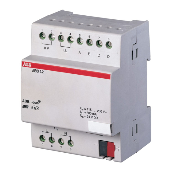
EIB / KNX General Product and Analogue Input AE/S 4.2 is a DIN rail mounted device for integration into functional overview the distribution board. The connection to the bus is established via a bus connection terminal at the front of the device. The physical address is assigned, and the parameters are set, using ETS 2, Version V1.3 or higher. -
Page 6: Device Technology
Device technology Analogue Input AE/S 4.2 is used to record analogue data. Four conventional sensors can be connected to AE/S 4.2. The connection to the bus is established using the enclosed bus connection terminal at the front of the device. The device is ready for operation after connecting the mains voltage of 115...230 V AC and the bus voltage. - Page 7 Threshold value measurement/1 Table 2: Application program Note: ETS2 V 1.3 or higher is required for programming. When using ETS3, a file of type “.VD3” must be imported. The application program is stored in ETS2/ETS3 under ABB/Input/Analogue Input, 4-fold.
-
Page 8: Circuit Diagrams
® ABB i-bus EIB / KNX Device technology Circuit diagrams AE/S 4.2 AE/S 4.2 ® = 115 . . . 230 V~ ® = 115 . . . 230 V~ ABB i-bus ABB i-bus = 300 mA = 300 mA... -
Page 9: Resolution And Accuracy Of The Individual Measuring Ranges
Requirements for commissioning In order to commission Analogue Input AE/S 4.2, a PC with ETS2 version V1.3 or higher is required as well as an interface to the bus, e.g. via an RS232 interface or via a USB interface. The device is ready for operation when the mains voltage of 230 V AC and the bus voltage have been applied. - Page 10 ® ABB i-bus EIB / KNX Device technology Supplied state Analogue Input is supplied with the physical address 15.15.255. The Threshold value measurement/1 application program is preloaded. It is therefore only necessary to load parameters and group addresses during commissioning. However the complete application program can be reloaded if required.
-
Page 11: Commissioning
Commissioning Commissioning Overview Analogue Input AE/S 4.2 is loaded with the “Threshold value measure- ment /1” application program. The programming requires ETS2 V 1.3 or higher. When using ETS3, a file of type “.VD3” must be imported. A maximum of 42 communication objects, 100 group addresses and 100 assignments can be linked. -
Page 12: Parameters
® ABB i-bus EIB / KNX Commissioning Parameters Note: The default settings for the options are underlined, e.g. Options: no/yes 3.2.1 Parameter window “General” Fig. 9: Parameter window “General” Behaviour after bus voltage recovery, Behaviour after mains voltage recovery, Behaviour after programming... - Page 13 ® ABB i-bus EIB / KNX Commissioning How does the device behave if the bus voltage recovers before the mains voltage? As the circuit is supplied by the mains voltage, it cannot react to the return of bus voltage event.
- Page 14 ® ABB i-bus EIB / KNX Commissioning – The “In Operation - System” communication object sends an “in operation” telegram – The “Status byte - System” communication object sends a status byte telegram Maximum telegram rate Options: 1/2/3/5/10/20 telegrams/second To control the bus load, this parameter can be used to limit the Maximum telegram rate per second.
-
Page 15: Parameter Window "Channel A - Voltage, Current And Resistance
® ABB i-bus EIB / KNX Commissioning 3.2.2 Parameter window “Channel A – Voltage, current and resistance” Fig. 10: Parameter window “Channel A – Voltage, current and resistance” Use channel Options: no/yes This parameter determines the use of channel A. -
Page 16: Definition Of The Measuring Range
® ABB i-bus EIB / KNX Commissioning 3.2.2.1 Definition of the measuring range Fig. 11: Parameter window “Channel A – Definition of the measuring range” The following 4 parameters are dependent on the Send output value as parameter. The preset values change depending on which byte value is set. - Page 17 ® ABB i-bus EIB / KNX Commissioning Output value to be sent for lower measuring limit [0...+ 255] Options: 0... 255 Output value to be sent for upper measuring limit [0...+ 255] Options: 0...+ 255 These two parameters are used to set the Output values to be sent for the lower and upper measuring limits [0...+ 255].
-
Page 18: Parameter Window "A - Output
® ABB i-bus EIB / KNX Commissioning 3.2.2.2 Parameter window “A – Output” Fig. 12: Parameter window “Channel A – Output” Scanning frequency The sensor signal of channel A is measured once per second. Filter Options: inactive low (mean value over 4 measurements) - Page 19 ® ABB i-bus EIB / KNX Commissioning Send output value Options: on request after a change cyclically after a change and cyclically This parameter is used to define how the Output value should be sent. If the on request option is selected, the “Request output value – Channel A”...
-
Page 20: Parameter Window "A - Threshold 1
® ABB i-bus EIB / KNX Commissioning 3.2.2.3 Parameter window The following section describes the parameters for threshold 1. These also “A – Threshold 1” apply to threshold 2. Fig. 13: Parameter window “Channel A – Threshold 1” Use threshold value... - Page 21 ® ABB i-bus EIB / KNX Commissioning Modify limits via the bus Options: no/yes This parameter is used to define whether it is possible to Modify limits via the bus. If yes is selected, the “Modify – Channel A threshold 1 lower limit”...
- Page 22 ® ABB i-bus EIB / KNX Commissioning If the 1 byte [0...255] option is set for the Data type of threshold value object parameter, the following parameters appear. Send if threshold value falls below [0...255] Options: 0...255 Send if threshold value exceeds [0...255] Options: 0...255...
-
Page 23: Parameter Window "A - Threshold 1 Output
® ABB i-bus EIB / KNX Commissioning 3.2.2.4 Parameter window The following section describes the parameters for the output of threshold 1. “A – Threshold 1 output” They also apply to the output of threshold 2. Fig. 14: Parameter window “Channel A – Threshold 1 output”... -
Page 24: Parameter Window "Channel A - Floating Contact Interrogation
® ABB i-bus EIB / KNX Commissioning 3.2.3 Parameter window “Channel A – Floating contact interrogation” Fig. 15: Parameter window “Channel A – Floating contact interrogation” Use channel Options: no/yes This parameter determines the use of channel A. Sensor output Options: 0 –... -
Page 25: Parameter Window "A - Output
® ABB i-bus EIB / KNX Commissioning 3.2.3.1 Parameter window “A – Output” Fig. 16: Parameter window “Channel A – Output” Send output value Options: on request after a change cyclically after a change and cyclically This parameter is used to define how the Output value should be sent. -
Page 26: Parameter Window "A - Threshold 1
® ABB i-bus EIB / KNX Commissioning 3.2.3.2 Parameter window The following section describes the parameters for threshold 1. These also “A – Threshold 1” apply to threshold 2. Fig. 17: Parameter window “Channel A – Threshold 1” Use threshold value... - Page 27 ® ABB i-bus EIB / KNX Commissioning Data type of threshold value object Options: 1 bit/1 byte [0...255] If the 1 bit option is set for the Data type of threshold value object parameter, the following parameters appear. Send if signal OFF...
-
Page 28: Parameter Window "A - Threshold 1 Output
® ABB i-bus EIB / KNX Commissioning 3.2.3.3 Parameter window The following section describes the parameters for the output of threshold 1. “A – Threshold 1 output” They also apply to the output of threshold 2. Fig. 18: Parameter window “Channel A – Threshold 1 output”... -
Page 29: "Channel A - Pt100 2-Conductor Technology
PT100 sensor must be routed separately to the 0 V terminal and may not be used as a return conductor for other sensors. Abb. 18: Parameterfenster „Kanal A PT100 2-Leiter-Technik –30 ... +70 °C“ Fig. 19: Parameter window “Channel A – PT100 2-conductor technology – 30...+ 70 °C”... - Page 30 ® ABB i-bus EIB / KNX Commissioning Sensor output Options: 0 – 1 V/0 – 5 V/0 – 10 V/1 – 10 V 0 – 20 mA/4 – 20 mA/0 – 1000 ohm/ Floating contact interrogation / PT100 2-conductor technology – 30...+ 70 °C/ PT100 2-conductor technology –...
-
Page 31: Line Fault Compensation Via Cable Length
® ABB i-bus EIB / KNX Commissioning 3.2.4.1 Line fault compensation via cable length Fig. 20: Parameter Line fault compensation “via cable length” Length of the cable, single distance [1...255 m] Options: 1...100...255 For setting the single cable length of the connected temperature sensor PT100. -
Page 32: Line Fault Compensation Via Cable Resistance
® ABB i-bus EIB / KNX Commissioning 3.2.4.2 Line fault compensation via cable resistance Fig. 21: Parameter Line fault compensation “via cable resistance” Cable resistance in milliohms [total of forward and return conductors] Options: 0...500...10000 For setting the cable resistance of the connected temperature sensor PT100. -
Page 33: Parameter Window "Calculation 1" With "Comparative" Calculation Type
® ABB i-bus EIB / KNX Commissioning 3.2.5 Parameter window The parameters for “Calculation 1, comparative” are described in the “Calculation 1” following section. The explanations also apply to calculations 2, 3 and 4. with “comparative” calculation type Fig. 22: Parameter window “Calculation 1, comparative”... - Page 34 ® ABB i-bus EIB / KNX Commissioning Input 1 Options: Channel A output value Channel B output value Channel C output value Channel D output value Input 2 Options: Channel A output value Channel B output value Channel C output value...
- Page 35 ® ABB i-bus EIB / KNX Commissioning Send output value Options: after a change after a change and cyclically This parameter is used to define how the Output value should be sent. Option After a change = Send output value after a change...
-
Page 36: Parameter Window "Calculation 1" With "Arithmetic" Calculation Type
® ABB i-bus EIB / KNX Commissioning 3.2.6 Parameter window The following section describes the parameters for “Calculation 1, arithme- “Calculation 1” tic“ which differ from the description of “Calculation 1, comparative“. with “arithmetic” The explanations also apply to calculations 2, 3 and 4. - Page 37 ® ABB i-bus EIB / KNX Commissioning Send output value as Options: 1-byte [0...+ 255] 1-byte [– 128...+ 127] 2-byte [0...+ 65,535] 2-byte [– 32,768...32,767] 2-byte [EIB floating point] 4-byte [IEEE floating point] This parameter is used to define the format in which the Output value should be sent.
-
Page 38: Communication Objects
® ABB i-bus EIB / KNX Commissioning Communication objects 3.3.1 Channel A Fig. 24: Communications objects – “Channel A” Function Object name Data type Flags Output value Channel A EIS variable C, R, T DPT variable This communication object is used to send the output value to the bus. The output value can... -
Page 39: Channels B, C And D
® ABB i-bus EIB / KNX Commissioning Function Object name Data type Flags Threshold value Channel A threshold 1 EIS variable C, R, T DPT variable As soon as the value exceeds or falls below the set threshold value, the following can be sent:... -
Page 40: Calculation 1
® ABB i-bus EIB / KNX Commissioning 3.3.3 Calculation 1 Fig. 25: Communication object “Calculation 1” No.. Function Object name Data type Flags Send output value Calculation 1 EIS variable C, R, T DPT variable This communication object is used to send the result of calculation 1. -
Page 41: General
® ABB i-bus EIB / KNX Commissioning 3.3.5 General Fig. 26: Communication objects “General” Function Object name Data type Flags In operation System EIS1, 1 bit C, R, T DPT 1.003 This communication object is active if “yes” has been selected in the “Send cyclical “in operation”... -
Page 42: Planning And Application
® ABB i-bus EIB / KNX Planning and application Planning and application Description of the How does the threshold value function? threshold value function 10,00 9,00 8,00 7,00 Threshold value 1: Upper limit 6,00 5,00 Threshold value 1: Lower limit... -
Page 43: Planning Example: "Humidity Sensor
® ABB i-bus EIB / KNX Planning and application Planning example: The air conditioning and heating in a laboratory is to be controlled in “Humidity sensor” relation to the relative humidity. If the value falls below 20%, the air conditioning should be switched off and the heating should be switched on. - Page 44 ® ABB i-bus EIB / KNX Planning and application Measurement curve for the connected humidity sensor: Measurement curve of the humidity sensor 100,00 90,00 80,00 70,00 60,00 50,00 40,00 30,00 20,00 10,00 0,00 0,00 100,00 200,00 300,00 400,00 500,00 600,00...
- Page 45 ® ABB i-bus EIB / KNX Planning and application Settings for the Channel A parameter window: Selection: 0 – 1000 Ohm Selection: 1 byte, as a value of 90 % should be sent. Fig. 30: Parameter window “Channel A – 0 - 1000 ohm”...
- Page 46 ® ABB i-bus EIB / KNX Planning and application Settings for threshold values 1 and 2 for channel A: Fig. 31: Parameter window “Channel A – 0 – 1000 ohm, threshold 1 and 2”...
-
Page 47: Planning Example: "Pt100 2-Conductor Technology - 30
® ABB i-bus EIB / KNX Planning and application Planning example: A container located outdoors, for storing liquids with a circulation pump, “PT100 2-conductor needs to be protected against minus temperatures (lower than 0 °C). technology – 30...+ 70 °C”... - Page 48 ® ABB i-bus EIB / KNX Planning and application Measurement curve of the PT100 Measuring range in °C Fig. 33: Measurement curve for the PT100 The two hatched lines indicate the possible further progression of the measurement curve. The manufacturer guarantees the standardised values for the measuring range from –...
- Page 49 ® ABB i-bus EIB / KNX Planning and application Settings for the Channel A parameter window: Selection: PT100 2-conductor technology -30...+70°C Fig. 35: Parameter window “Channel A – PT100 2-conductor technology – 30...+ 70 °C” Settings for threshold values 1 and 2:...
-
Page 50: Planning Example: "Air Flow Measurement
® ABB i-bus EIB / KNX Planning and application Planning example: In a ventilation system, ventilation flaps should be controlled based on air “Air flow measurement” flow measurement. The ventilation flaps should be opened at an air flow of 10 m/s and closed at an air flow of 8 m/s. In addition, an “ON telegram”... - Page 51 ® ABB i-bus EIB / KNX Planning and application Settings for the Channel A parameter window: Fig. 39: Parameter window “Channel A, 4 - 20 mA” Settings for threshold values 1 and 2: Fig. 40: Parameter window “Channel A, 4 – 20 mA, threshold 1 and 2”...
- Page 52 ® ABB i-bus EIB / KNX...
-
Page 53: Appendix
ABB i-bus EIB / KNX Appendix Anhang Analogue Input AE/S 4.2 is supplied with the following parts. Scope of delivery Please check the scope of delivery against the following list. – 1 x AE/S 4.2, Analogue Input, 4-fold, MDRC – 1 x installation and operating instructions –... - Page 54 ® ABB i-bus EIB / KNX Appendix An example: If the measurement range is not fully used, the conditions for the measured value out of range communication object change. A sensor with the following properties should be connected to the analog input.
- Page 55 ® ABB i-bus EIB / KNX Appendix Upper measurement limit: At more than 5 %, i.e. 5 % of 90 % => 4.5 % = 94.5 % => 945 ohms. If 94.5 % is exceeded, the measured value out of range communication object sends.
-
Page 56: Truth Table For The "Status Byte - System" Communication Object
® ABB i-bus EIB / KNX Appendix Truth table for the “Status byte – System” communication object 169 A9 170 AA 171 AB 172 AC 173 AD 174 AE 175 AF 176 B0 177 B1 178 B2 179 B3 180 B4... -
Page 57: List Of Tables
® ABB i-bus EIB / KNX Appendix Fig. 1: Analogue Input AE/S4.2 ......... . 4 List of diagrams Fig. -
Page 58: Index
® ABB i-bus EIB / KNX Appendix Resolution ............. . . 4, 7 Index Output range . -
Page 59: Ordering Information
Ordering information Description Ordering information Price Unit Pack. 40 16779 group weight unit Short code Order no. [kg] [pc.] Analogue Input, 4-fold MDRC AE/S 4.2 2CDG 110 030 R0011 58092 2 Table 11: Ordering information for Analogue Input, 4-fold, MDRC... -
Page 60: Notes
® ABB i-bus EIB / KNX Appendix Notes VIII... - Page 61 The information in this leaflet is subject to change without further notice. Your EIB-Partner...