Table of Contents
Advertisement
Quick Links
Advertisement
Table of Contents

Related Manuals for ABB RAIO-01


Summary of Contents for ABB RAIO-01
- Page 1 ABB Drives User’s Manual Analogue I/O Extension Module RAIO-01...
- Page 3 Analogue I/O Extension Module RAIO-01 User’s Manual 3AFE64484567 REV B EN EFFECTIVE: 2009-04-21 © 2009 ABB Oy. All Rights Reserved.
-
Page 5: Safety Instructions
Overview This chapter states the general safety instructions that must be followed when installing and operating the RAIO-01 Analogue I/O Extension module. The material in this chapter must be studied before attempting any work on, or with, the unit. In addition to the safety instructions given below, read the complete safety instructions of the specific drive you are working on. - Page 6 Safety instructions RAIO-01 User’s manual...
-
Page 7: Table Of Contents
The RAIO-01 module ........ - Page 8 Option slot installation ........21 AIMA-01 I/O Module Adapter installation ......21 Appendix A – Technical data RAIO-01 User’s manual...
-
Page 9: Chapter 1 - Introduction
Intended The manual is intended for the people who are audience responsible for commissioning and using an RAIO-01 Analogue I/O Extension module with the ACS800 drive. The reader is expected to have a basic knowledge of electrical fundamentals, electrical wiring practices and how to operate the drive. -
Page 10: What This Manual Contains
Safety instructions are featured in the first few pages of this manual. Chapter 2 – Overview contains a short description of the RAIO-01 Analogue I/O Extension module, a delivery checklist and warranty information. Chapter 3 – Installation contains instructions for module hardware settings, mounting and cabling. -
Page 11: Chapter 2 - Overview
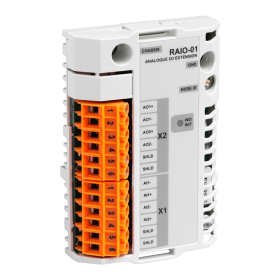
Overview This chapter contains a short description of the Analogue I/O Extension module, a delivery checklist and warranty information. The RAIO-01 The RAIO-01 Analogue I/O Extension module offers module two bipolar current ( 0[4]…20 mA) or voltage ± 0[2]…10 V or 0…2 V) inputs and two unipolar... -
Page 12: Delivery Check
The option package contains: • RAIO-01 module • Two screws • This manual. Compatibility The RAIO-01 is compatible with the ACS800 Standard Application Program version ASXR7000 or later. Warranty and The warranty for your ABB drive and options covers liability manufacturing defects. -
Page 13: Chapter 3 - Installation
Hardware Manual of the drive. Mounting The RAIO-01 is to be inserted into an optional module slot on either the RMIO board of the drive, or on an AIMA-01 I/O Module Adapter. The module is held in place with plastic retaining clips and two screws. -
Page 14: Mounting Onto Aima Adapter
3. Remove the cover of the module enclosure (see page 15). 4. Set the configuration DIP switches of the module to the required position (pages and 17). 5. Set the node ID for the module (page 20) and refit the cover. RAIO-01 User’s manual... -
Page 15: Removing And Refitting The Cover Of The Enclosure
1 2 3 4 5 6 AI1 signal mode 1 2 3 4 5 6 1 2 3 4 5 6 AI1 signal level AI2 signal mode AI2 signal level Figure 2 Top view of the module, cover removed RAIO-01 User’s manual... -
Page 16: Input Mode Selection
± 0(2)…10 V ± ±0…2 V 1 2 3 4 5 6 1 2 3 4 5 6 0(4)…20 mA 0(2)…10 V 0…2 V (Default) 1 2 3 4 5 6 1 2 3 4 5 6 RAIO-01 User’s manual... -
Page 17: Input Signal Type Selection
1 2 3 4 5 6 Voltage signal ±0(2)…10 V 1 2 3 4 5 6 1 2 3 4 5 6 Voltage signal ±0…2 V 1 2 3 4 5 6 1 2 3 4 5 6 RAIO-01 User’s manual... -
Page 18: Terminal Designations
Chapter 3 – Installation Terminal The RAIO-01 is equipped with two 6-pole non- designations detachable screw-type connectors. Terminal block X1 provides the connection for the analogue input signals, and X2 provides the connection for the analogue output signals. Each terminal block includes two terminals for... -
Page 19: Wiring
0.5 to 1.5 mm twisted pair cable with individual and/or overall shields should be used for analogue signals. The shields should be connected to the SHLD terminals on the RAIO-01 module. See the example below. RAIO-01 Transducer 1 Indicator 1... -
Page 20: Node Id Selection
Chapter 3 – Installation Node ID selection If the RAIO-01 module is mounted onto an external AIMA-01 I/O Module Adapter, choose the proper node ID for the module using the node ID selector (S1, range 1…15). Setting the node ID is not required when the module is mounted into SLOT 1 or SLOT 2 on the drive. - Page 21 Chapter 4 – Fault tracing Status LED There is one status LED (WD/INIT, yellow) on the RAIO-01 module. The LED is lit when the drive is configuring the module at power-up. Option slot In case the LED does not go out after one second: installation •...
- Page 22 Chapter 4 – Fault tracing RAIO-01 User’s manual...
- Page 23 • One DIP switch per input for selection between bipolar mode (default) and unipolar mode • Two DIP switches per input for signal type and level selection Connectors: • 38-pin parallel bus connector • Two 6-pole non-detachable screw-type terminal blocks for max. 2.5 mm wire RAIO-01 User’s manual...
- Page 24 48 V rms; the maximum peak value is 100 V. The isolation towards the chassis potential (e.g. GND and +24 VDC of the module carrier board) has been tested at 1.5 kV AC for 1 s. RAIO-01 User’s manual...
- Page 25 100 mA (5 V) + 120 mA (24 V) Both voltages supplied by the RMIO board or AIMA-01 I/O Module Adapter • Estimated min. lifetime: 100 000 h • All materials UL/CSA-approved • Complies with EMC standards EN 50081-2 and EN 50082-2 RAIO-01 User’s manual...
- Page 26 Appendix A – Technical data RAIO-01 User’s manual...
- Page 28 ABB Oy ABB Inc. AC Drives Drives & Power Products P.O. Box 184 16250 West Glendale Drive FIN-00381 Helsinki New Berlin, WI 53151 FINLAND Telephone:+358 10 22 11 Telephone:262 785-8378 Fax: +358 10 222 2681 800 243-4384 Internet: www.abb.com Fax:...