Table of Contents
Advertisement
Advertisement
Table of Contents

Related Manuals for ABB S800


Summary of Contents for ABB S800
- Page 1 S800 I/O Product Guide Power and productivity for a better world™...
- Page 3 S800 I/O Product Guide...
- Page 4 This document contains information about one or more ABB products and may include a description of or a reference to one or more standards that may be generally relevant to the ABB products. The presence of any such description of a standard or reference to a standard is not a representation that all of the ABB products referenced in this document support all of the features of the described or ref- erenced standard.
-
Page 5: Table Of Contents
Section 1 - Key Benefits Product Benefits ......................18 Features..........................19 Section 2 - Product Description Introduction ........................21 Product Overview ......................24 S800 I/O Station ....................26 Base Cluster ......................26 I/O Cluster ......................26 I/O Modules ......................26 Functional Description ....................28 Product Configuration Examples .................28 Communication ....................30 Fieldbus Communication Interface ..............35... - Page 6 Table of Contents Drives Integration ....................52 Support for connections to instruments in Hazardous Areas....... 55 Support for Externally Connected Accessories ........... 56 Support for HART Communication..............58 Support for Safety System Requirements ............59 Redundancy Functionality ................... 59 Software Components ..................... 60 Hardware Components....................
- Page 7 Advant Fieldbus 100 Load .................121 PROFIBUS CI801....................125 PROFIBUS CI840....................131 S800 I/O Station Data Scanning ................138 Calculation of Maximum Distance of an Optical ModuleBus Configuration ...143 Power Supply and Cooling Requirements ............147 Supported I/O Modules and Drives via Advant Fieldbus 100........159 Supported I/O Modules and Drives via PROFIBUS and CI801........159...
- Page 8 Table of Contents 3BSE015969-600 A...
-
Page 9: About This Product Guide
This Product Guide does not describe the different controller connect products. For more details, see separate product guides. The product guide is intended as an introduction to S800 I/O system, as well as a reference when discussing technical solutions with customers. -
Page 10: Product Guide Conventions
Product Guide Conventions About This Product Guide • Technical and Performance data for S800 I/O system. • Instructions on how to order, with reference to system configurations. Product Guide Conventions Microsoft Windows conventions are normally used for the standard presentation of material when entering text, key sequences, prompts, messages, menu items, screen elements, etc. -
Page 11: Terminology
About This Product Guide Terminology Terminology A complete and comprehensive list of terms is included in System 800xA System Guide Functional Description (3BSE038018*). The listing includes terms and definitions that apply to the 800xA System where the usage is different from commonly accepted industry standard definitions and definitions given in standard dictionaries such as Webster’s Dictionary of Computer Terms. - Page 12 Terminology About This Product Guide Term Description I/O station An I/O station consists of one or two FCI(s), 1-7 I/O clusters and up to 24 I/O devices. ModuleBus Is an incremental, electrical or optical, bus for interconnection of I/O devices. (ModuleBus) Is used when extending the electrical ModuleBus (within Extension cable...
-
Page 13: Released User Manuals And Release Notes
New functions in the S800 I/O system: • CSA and FM are removed for all modules except s800 IS modules. Always check which S800 I/O feature support is included in the controller that the I/O is connected to. 3BSE015969-600 A... - Page 14 New in this Release About This Product Guide 3BSE015969-600 A...
- Page 15 Safety Summary Electrostatic Sensitive Device Devices labeled with this symbol require special handling precautions as described in the installation section. GENERAL Equipment Environment WARNINGS All components, whether in transportation, operation or storage, must be in a non-corrosive environment. Electrical Shock Hazard During Maintenance Disconnect power or take precautions to insure that contact with ener- gized parts is avoided when servicing.
- Page 16 Safety Summary 3BSE015969-600 A...
-
Page 17: Section 1 Key Benefits
Section 1 Key Benefits The S800 I/O is a distributed, highly modularized and flexible I/O-system with eco-efficient design, providing easy installation of the I/O modules, process cabling and connection to drives systems. The S800 I/O modules and termination units can be mounted and combined in many different configurations to fit your space requirements and suit many types of applications. -
Page 18: Product Benefits
Product Benefits Section 1 Key Benefits Product Benefits Some of the benefits of the S800 I/O system are: • Flexibility, permitting a virtually infinite number of installation arrangements for any application: – small to large – easy mounting on a DIN-rail •... -
Page 19: Features
An electrical ID is checked at start-up, if this does not match the configured type, the I/O module is not taken into operation. • Hot swap of S800 I/O modules (except S800L modules) allowing replacement of faulty modules without disconnecting field power or system power to the I/O station. - Page 20 Features Section 1 Key Benefits • HART pass-through communication. • I/O modules allow for 55 C ambient temperature except for vertical mounted Compact MTU with I/O modules and vertically mounted S800L allow for C ambient temperature. • Support of connection to external Intrinsic Safety Barriers. •...
-
Page 21: Section 2 Product Description
Section 2 Product Description Introduction shows the basic construction of I/O stations without any redundancy. Figure 2 To increase the up-time, a number of component can be set up with redundancy: • Power Supply • I/O Module • Fieldbus Communication Interface (FCI) •... - Page 22 Introduction Section 2 Product Description Controller I/O Module Electrical ModuleBus Base Cluster ModuleBus Optical Port Optical ModuleBus Modem Fieldbus I/O Station I/O Cluster I/O Cluster Optical ModuleBus Base Cluster Figure 2. I/O Station Overview 3BSE015969-600 A...
- Page 23 Section 2 Product Description Introduction An example of a system using redundancy for all these components is shown in Figure Redundant Controller Redundant Redundant I/O module Redundant electrical ModuleBus ModuleBus Optical Port Optical ModuleBus Modem I/O Cluster, single I/O Redundant Fieldbus I/O Cluster, single I/O Optical...
-
Page 24: Product Overview
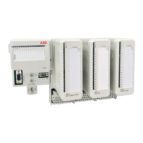
Product Overview S800 I/O provides distributed I/O on PROFIBUS and Advant Fieldbus 100 (AF100). S800 I/O is also used as a communication link to some of ABB’s Drives. With the network definition PROFIBUS, it means both the versions; PROFIBUS-DP and PROFIBUS-DPV1. - Page 25 Product Overview Figure 4. S800 I/O Station In general, all S800 I/O units are G3 compliant. G3 compliant units withstand more severe environmental conditions according to ISA-S71.04. The following S800 I/O units are G2 compliant - SD831, SD832, SD833, SD834, SS832, and TB811. G3 compliant versions of SD822 and SS822 are available, refer to SD822Z and SS822Z.
-
Page 26: S800 I/O Station
12 S800 I/O modules. I/O Modules Any combination of I/O modules is possible, within the limits in Table Table 1. The max. I/O Configuration of S800 I/O Connected to Advant Fieldbus 100 and PROFIBUS. Item Max. No. S800 I/O stations per Advant Fieldbus 100... - Page 27 Technical Data and Performance (1) If other than S800 I/O stations are used on the same Advant Fieldbus 100, the maximum number of S800 I/O stations must be reduced with a corresponding number of stations. (2) Without Optical ModuleBus Expansion the maximum number is 12.
-
Page 28: Functional Description
This section includes some basic configuration examples, to give you some ideas about the use of S800 I/O. PROFIBUS An S800 I/O station can be connected to a PROFIBUS network using the Fieldbus Communication Interface (FCI) CI801/CI840. PROFIBUS master PROFIBUS... - Page 29 Communication Interface CI840 and redundant I/O modules. PROFIBUS master PROFIBUS master Other PROFIBUS slaves S800 I/O station with redundant CI840 Figure 6. A PROFIBUS-DPV1 Configuration with Redundancy Example Advant Fieldbus 100 with or without media redundancy Media redundancy on Advant Fieldbus 100 includes redundant cable, redundant modems and the CI810 FCI.
-
Page 30: Communication
Advant Fieldbus 100, the communication interface module and its S800 I/O modules are called as S800 I/O station. An S800 I/O station works as a slave for one parent controller. If several S800 I/O stations are connected to the same Advant Fieldbus 100 together with more than one controller, each S800 I/O station needs its own dedicated parent controller. - Page 31 A Fieldbus Communication Interface module communicates with its S800 I/O modules over the ModuleBus. It communicates internally in the base cluster and externally with other additional clusters within the same S800 I/O station by using Optical ModuleBus Modems TB820, TB840 or TB840A. The Optical ModuleBus Modems are connected via optical cables to a ModuleBus Optical port module on the communication interface module.
- Page 32 15m (50ft) with plastic fiber, 200m (656ft) with HCS fiber and up to 5000m (20000m for S800 I/O HI) by using TB826 Optical Media Converter. Factory made optical cables (plastic fibre) are available in lengths of 1.5, 5 and 15 m (5, 16.7 or 50 ft).
- Page 33 Section 2 Product Description Communication • star configuration with the Optical Media Converter. See Figure Maximum length of any cable is: I/O Station 15 m (49 ft.) for plastic fiber 200 m (667 ft.) for HCS glass fiber Rx Tx Cluster 1 Cluster 2 Cluster 3...
- Page 34 Communication Section 2 Product Description Figure 12. ModuleBus configuration with Optical Media Converter TB825/ TB826 3BSE015969-600 A...
-
Page 35: Fieldbus Communication Interface
Section 2 Product Description Fieldbus Communication Interface Fieldbus Communication Interface A Fieldbus Communication Interface module is used as communication interface to connect S800 I/O modules to the fieldbus. There are five different FCI modules: • CI801 – for PROFIBUS-DPV1 •... - Page 36 Fieldbus Communication Interface Section 2 Product Description optional user text and item number are also provided. The communication plugs can be inserted/removed without interrupting the communication between stations on the bus. The type designation CI810 in this document includes all types of models CI810, CI810V1, CI810V2, CI810A and CI810B if no other information is given.
-
Page 37: Module Termination
Section 2 Product Description Module Termination Module Termination The MTUs are totally passive units and all active circuitry is allocated to the I/O module containing process connections and ModuleBus part. For more details, refer Module Termination Unit on page 63. Table 3. - Page 38 Module Termination Section 2 Product Description Table 3. S800M I/O Termination Units (Continued) Module Description Type TU830/ Extended MTU, 3 16 + 2 4 terminals, 50 V. Typically used with 24/48 TU830V1 V d.c binary and -20 - +20 mA analog modules. Provides terminals for field power distribution.
- Page 39 Section 2 Product Description Module Termination Table 3. S800M I/O Termination Units (Continued) Module Description Type TU842 Redundant horizontal MTU, 3 16 + 2 4 terminals, 50 V for redundant I/O modules TU843 Redundant vertical MTU, 3 16 + 2 4 terminals, 50 V for redundant I/O modules TU844...
-
Page 40: Modulebus Items
ModuleBus Items Section 2 Product Description Table 3. S800M I/O Termination Units (Continued) Module Description Type Mounting Used for horizontal mounting of CI801, CI840 and TB840 on a vertical DIN-rail. Horizontal Mounting profile with one DIN-rail and one cable duct. Mounting Profile (1) Connector is not enclosed. - Page 41 Section 2 Product Description ModuleBus Items Table 5. ModuleBus Items Module Type Description TB810 ModuleBus Optical port with 10 Mbit driver for ModuleBus Optical expansion used together with S800I/O and Drive equipment Option to the communication interface. Used together with CI810 and CI820.
- Page 42 ModuleBus Items Section 2 Product Description Table 5. ModuleBus Items (Continued) Module Type Description TK811V015 Optical ModuleBus expansion cable with connectors, duplex cable plastic fibre1.5 m (4.9 ft.) TK811V050 Optical ModuleBus expansion cable with connectors, duplex cable plastic fibre 5 m (16.4 ft.) TK811V150 Optical ModuleBus expansion cable with connectors,...
-
Page 43: I/O Modules
All I/O modules are supervised at system start-up as well as under normal operation. The status of an S800 I/O module is indicated with front mounted LEDs; RUN (R), green, normal operation, FAULT (F), red, when a fault is detected, WARNING (W),... - Page 44 Some output modules and modules with Intrinsic Safety interfaces have indication for the channel error status. The S800 I/O modules 24/48 V d.c. have channels isolated in groups. Each group has a field power status input to indicate presence of field power. The loss of field power is indicated on Warning LED, module status set to warning and channel status set to error.
- Page 45 Section 2 Product Description I/O Modules Table 6. S800 Digital Modules (Continued) Module Description Type DI818 Digital Input 24 V, 2*16 channels Current Sinking Rated isolation voltage 50 V Digital Input 120 V a.c., 110 V d.c., 8*1 channels ...
- Page 46 I/O Modules Section 2 Product Description Table 6. S800 Digital Modules (Continued) Module Description Type DO801 L Digital Output 24 V d.c. 0.5 A protected, 1*16 channels Rated insulation voltage 50 V DO802 L Digital Output Relay 8*1 channels, 24-230 V a.c./110 V d.c.
- Page 47 Section 2 Product Description I/O Modules Table 6. S800 Digital Modules (Continued) Module Description Type Digital Output 24 V d.c. 0.5 A protected, DO840 2*8 channels Rated insulation voltage 50 V. Advanced on-board diagnostics. For single and redundant applications.
- Page 48 4 or 8 channels. Some of the modules also has isolation between channels. The modules have the standard set of module status indicators. The open circuit detection is available for inputs and outputs configured for 4…20 mA and for the RTD and TC inputs. Table 7. S800 Analog Modules Module Description Type L Analog Input 1*8 channels.
- Page 49 Section 2 Product Description I/O Modules Table 7. S800 Analog Modules (Continued) Module Description Type AI830/ Analog Input 1*8 ch, Pt100 (-80...80 C, -200...250 C, C), AI830A -200...850 C), Ni100 (-60...180 Ni120 (-80...260 C), Cu10 (-100...260 C) Resistor (0...400 ), 14 bit....
- Page 50 I/O Modules Section 2 Product Description Table 7. S800 Analog Modules (Continued) Module Description Type AI880/ High Integrity Analog Input 1*8 channels. 0...20 mA, AI880A 4...20 mA For single and redundant applications. AI880A has support for HART pass-through communication. Complies with the NAMUR recommendation NE43.
- Page 51 Section 2 Product Description I/O Modules Table 7. S800 Analog Modules (Continued) Module Description Type AO820 Analog Output 4*1 channels, -20…20 mA, 0...20 mA, 4...20 mA, -10…10 V, 0...10 V, 2...10 V, 12 bit + sign, 0.1%, individually isolated....
-
Page 52: Drives Integration
Section 2 Product Description Drives Integration The ABB Standard and Engineered drives can be connected to the S800 I/O system. The FCI works as a communication link between the fieldbus master and the drives. No application software concerning this functionality is stored in the FCI. Check the available support for each FCI type. - Page 53 The process data are measured with improved accuracy for even more exact process control, while the ready-made information permits a total overview of the drives in the process. Features The ABB drives integration includes features such as: • Fieldbus solutions which results in lower wiring costs. •...
- Page 54 Drives Integration Section 2 Product Description Figure 13. Examples of Drives Integration Information from the drives: The process values are sent as cyclic data, with an updating frequency decided by the application engineer. The data enables the control system to have access to basic information such as speed, current, torque and diagnostic information.
-
Page 55: Support For Connections To Instruments In Hazardous Areas
I/O modules and with support for external Intrinsic Safety systems. The S800 I/O includes I/O modules and MTU with Intrinsic Safety interfaces, namely AI890, AI893, AI895, AO890, AO895, DI890, DO890 and TU890. The interfaces are classified Ex ia, Group IIC and the modules are ATEX certified. -
Page 56: Support For Externally Connected Accessories
S800 I/O modules and a special MTU. The supported Intrinsic Safety System is the HiD Series 2000. The S800 I/O modules are connected via MTU TU812/TU812V1, a standard cable from Pepperl+Fuchs and a specific adapter board, one for each I/O module types... - Page 57 Connection to ABB Entrelec Interfast Pre-wiring Solutions ABB Entrelec offers solutions for fast termination solutions with pre-wired cables and an assortment of terminations and signal adaptions. This offer connects to S800 I/O via the TU812 termination unit which provides a D-sub connector. Multipurpose cables are also available.
-
Page 58: Support For Hart Communication
Support for HART Communication Section 2 Product Description to S800 I/O via the TU812 termination unit which provides a D-sub connector. For further information, refer the link www.s800connection.com. Support for HART Communication S800 I/O provides possibilities to communicate via HART protocol with HART Field Devices via PROFIBUS-DPV1 using CI840 or CI801 or AF100 using CI810 or CI820. -
Page 59: Support For Safety System Requirements
Section 2 Product Description Support for Safety System Requirements Support for Safety System Requirements The High Integrity I/O is certified for EN 61508-SIL3. The High Integrity I/O has to be used together with a certified controller to comply with the standards. There are three modules that belong to the High Integrity I/O family that are certified for these standards, AI880/AI880A, DI880 and DO880. -
Page 60: Software Components
The software is installed at delivery. The upgrades are available for download for the system software for field upgrade. The cables to connect a standard PC with the FCI are available in the S800 I/O price list. -
Page 61: Hardware Components
S800 I/O modules are mounted on standard DIN-mounting rails according to EN50022 NS 35/7,5. An S800 I/O station can consist of a base cluster and up to 7 additional I/O clusters. The base cluster consists of a communication interface module and up to 12 I/O modules. - Page 62 I/O Modules Section 2 Product Description Next module Centre of DIN-rail 58,5 Figure 16. Dimensions for S800L Modules 3BSE015969-600 A...
-
Page 63: Module Termination Unit
Section 2 Product Description Module Termination Unit 58.5 Figure 17. S800L Module with TU805 Module Termination Unit Module Termination Units (MTUs) act as I/O module carriers and are available as Compact, Extended, Intrinsic Safety and Redundant MTUs. A Compact MTU normally offers termination of one wire per channel for a 16 channel module. - Page 64 The S800 I/O modules can be inserted and removed from MTUs without disturbing system operation. The physical lock for S800 I/O which locks an I/O module to its MTU allows I/O module removal only when the lock is in its unlocked position. The locking mechanism also acts as a logic lock so that an I/O module is operable only when the lock is in the locked position.
- Page 65 Section 2 Product Description Module Termination Unit Figure 18. Typical Extended MTU with I/O Module 3BSE015969-600 A...
- Page 66 Module Termination Unit Section 2 Product Description Figure 19. Typical Compact MTU with I/O Module 3BSE015969-600 A...
- Page 67 Section 2 Product Description Module Termination Unit 122 mm (4.8”) 7 mm (.27”) Center of DIN-rail 8 mm (0.31”) 5 mm 31.5 mm (0.2”) (1.24") 9 mm 40 mm 58 mm (0.35”) (2.28”) (1.57”) 58.5 mm (2.30”) Figure 20. Compact MTU for Intrinsic Safety without and with I/O Module 3BSE015969-600 A...
- Page 68 Module Termination Unit Section 2 Product Description Figure 21. Typical Horizontal Redundant MTU 3BSE015969-600 A...
- Page 69 Section 2 Product Description Module Termination Unit 122 mm (4.8”) Figure 22. MTU with I/O Module 3BSE015969-600 A...
-
Page 70: Fieldbus Communication Interface
Fieldbus Communication Interface Section 2 Product Description Fieldbus Communication Interface The Fieldbus Communication Interface (FCI) module is a configurable communication interface which performs operations such as signal processing, gathering of various supervision information, OSP handling and configuration of re-inserted I/O modules. The FCI connects to a controller by way of different types of fieldbuses. - Page 71 Section 2 Product Description Fieldbus Communication Interface Figure 24. CI810 FCI Dimensions 3BSE015969-600 A...
- Page 72 Fieldbus Communication Interface Section 2 Product Description Figure 25. CI820 FCI Dimensions 3BSE015969-600 A...
- Page 73 Section 2 Product Description Fieldbus Communication Interface Figure 26. TB815 Interconnection Unit Dimensions 3BSE015969-600 A...
- Page 74 Fieldbus Communication Interface Section 2 Product Description Figure 27 shows the TB815 configured with two CI820 FCIs for redundant operation. SERVICE SERVICE STN. ADDR STN. ADDR x 10 x 10 CI820 TB815 CI820 SWX.X/Y SWX.X/Y L+ L+ L+ L+ AF100 AF100 Figure 27.
- Page 75 Section 2 Product Description Fieldbus Communication Interface 128 mm (5.04”) 124 mm (4.88”) 162 mm 186 mm (6.38”) (7.32”) Figure 28. Redundant CI840 FCI and MTU TU847. 3BSE015969-600 A...
- Page 76 Fieldbus Communication Interface Section 2 Product Description Figure 29. Dimension for typical MTU for CI840 or TB840 S800M I/O modules may be exchanged during system operation. A module locking mechanism disconnects ModuleBus and process signals safely from the module. A newly inserted I/O module is automatically put into operation if the system identifies the module being correct type and without faults.
-
Page 77: Modulebus
Section 2 Product Description ModuleBus ModuleBus TB820/TB820V2 ModuleBus Modem The TB820/TB820V2 ModuleBus Modem is a fiber optic interface to the ModuleBus. The ModuleBus Modem has an electrical and an optical interface which are logically the same bus. A maximum of 12 I/O modules can be connected to the electrical ModuleBus and up to seven clusters can be connected to the fiber optic ModuleBus. - Page 78 ModuleBus Section 2 Product Description Figure 30. TB820/TB820V2 ModuleBus Modem 3BSE015969-600 A...
- Page 79 Section 2 Product Description ModuleBus TB840/TB840A ModuleBus Modem and TU807/TU840/TU841/TU848/TU849 Module Termination Unit The TB840/TB840A ModuleBus Modem is a fiber optic interface to the Optical ModuleBus. TB840/TB840A is used in redundancy configurations where each module is connected to different Optical ModuleBus lines, but connected to the same electrical ModuleBus.
- Page 80 ModuleBus Section 2 Product Description 128 mm (5.04”) 47 mm (1.85”) 124 mm (4.88”) 162 mm 186 mm (6.38”) (7.32”) Only TU848/TU849 Figure 31. TB840 and TU840/TU841 3BSE015969-600 A...
- Page 81 Section 2 Product Description ModuleBus TB825 Optical Media Converter ModuleBus Optical Media Converter, converts between plastic opto fiber or HCS fiber with Versatile link connectors and glass optical fiber with ST connectors. The TB825 is built in S800L mechanics and DIN-rail mounted. 85.6 14.2 57.2...
- Page 82 ModuleBus Section 2 Product Description TB826 Optical Media Converter TB826 is a Long Range Optical Media Converter for the ModuleBus. It is used to convert between plastic/opto fiber or HCS fiber with Versatile link connectors and single mode field fiber with SC connector. The TB826 is built in S800L mechanics and DIN-rail mounted.
- Page 83 Section 2 Product Description ModuleBus ModuleBus Optical Port, TB810/TB811 The ModuleBus Optical ports TB810/TB811 have two connectors for the Optical ModuleBus expansion and one connector for connection to the Fieldbus Communication Interface module, (FCI). The ModuleBus Optical ports are used together with the communication modules CI810, CI820/CI820V1 and (TB815).
- Page 84 ModuleBus Section 2 Product Description ModuleBus Optical Port, TB842 The ModuleBus Optical port TB842 has two connectors for the Optical ModuleBus expansion and one connector for connection to the Fieldbus Communication Interface module, (FCI). The ModuleBus Optical ports are used together with the communication modules CI801 or CI840.
- Page 85 Wave length: 820 nm • Max cable attenuation: 3.5 dB (1000 m of unspliced cable) TB826 Field Optical Cable. Glass Optical Fiber, single mode up to 5000m (20000m for S800 I/O HI) • Fiber dimensions: 9/125 µm • Connector type: SC •...
- Page 86 ModuleBus Section 2 Product Description ModuleBus Extension Cable Adaptors TB805, TB806 for single ModuleBus The ModuleBus extension cable adaptors exist in two types for bus outlet and bus inlet. The adaptors have two connectors for the electrical ModuleBus and for the ModuleBus extension cable.
- Page 87 Section 2 Product Description ModuleBus ModuleBus Extension Cable Adaptors TB845, TB846 for dual ModuleBus The ModuleBus extension cable adaptors for dual electrical ModuleBuses exists in two types for ModuleBus outlet and ModuleBus inlet. The adaptors have two connectors for the electrical ModuleBus and two for the ModuleBus extension cable.
- Page 88 ModuleBus Section 2 Product Description Figure 37. Module Outlet Module TB845 3BSE015969-600 A...
- Page 89 Section 2 Product Description ModuleBus Figure 38. ModuleBus Inlet Module TB846 3BSE015969-600 A...
- Page 90 ModuleBus Section 2 Product Description ModuleBus Terminator Module TB807 There must be a ModuleBus terminator module at the end of each electrical ModuleBus. ModuleBus Connector (X1) Top View 18 mm (0,71”) 13 mm (0,52”) TB807 19 mm (0,75”) ModuleBus Terminator Latch MTU Assembly (0,52”)
-
Page 91: Power Supplies
The power supplies SD831, SD832, SD833, and SD834(24 V output) can be used to power processor modules and S800 I/O modules, through the processor unit, and to power 24 V field circuits (optional). The primary side can connect to industrial mains installation class III (IEC664). - Page 92 Power Supplies Section 2 Product Description Table 9. Power Supplies (Continued) Module Type Description SD834 Power Supply 100/240 V a.c./24 V d.c. 20 A Rated insulation voltage 300 V. SS822Z Voting Device 20 A. Dual d.c. 24 V to single 24 V. Rated insulation voltage 50 V.
- Page 93 Section 2 Product Description Power Supplies Figure 40. Power Supply Module SD831 3BSE015969-600 A...
- Page 94 Power Supplies Section 2 Product Description Power Supply Module SD832 Figure 41. 3BSE015969-600 A...
- Page 95 Section 2 Product Description Power Supplies Power Supply Module SD833 Figure 42. 3BSE015969-600 A...
- Page 96 Power Supplies Section 2 Product Description Power Supply Module SD834 Figure 43. 3BSE015969-600 A...
- Page 97 Section 2 Product Description Power Supplies Figure 44. Voting Unit SS823 3BSE015969-600 A...
- Page 98 Power Supplies Section 2 Product Description Voting Unit SS832 Figure 45. 3BSE015969-600 A...
-
Page 99: Mounting Equipment
Section 2 Product Description Mounting Equipment Mounting Equipment Mounting Kit for CI801/CI840/CI840A/TB840/TB840A The Mounting Kit is used for horizontal mounting of CI801/CI840/CI840A and TB840/TB840A on a vertical DIN-rail. This enables the higher range of the ambient temperature for CI801/CI840/CI840A and TB840/TB840A. Apart from MTUs for CI840, TB840 can also be ModuleBus cable adapters mounted on the Mounting Kit. - Page 100 Figure 47. Configurations for mounting of MTUs on the Mounting Kit Prefabricated Aluminium Profile Prefabricated aluminium profile for mounting of S800 I/O modules in cabinets or other types of installations. The profile supports good mechanical stability and chassis ground connection.
- Page 101 Section 2 Product Description Mounting Equipment Screws for fastening in Groove for environments with fastening screws high vibrations Figure 48. MTU mounted on aluminium profile The profile has grooves for self-tapping screws (ST 4.8×9.5) that can be used for fastening the modules in an environment with high vibrations. The aluminum profiles have one DIN-rail and one cable duct and are available in different sizes.
- Page 102 Mounting Equipment Section 2 Product Description 482 mm (19") 465 mm (18.31") 40 mm (1.57") 76 mm (2.99") Figure 49. Prefabricated Aluminium Profile Dimensions 3BSE015969-600 A...
-
Page 103: G3 Compliant Modules
Section 2 Product Description G3 compliant modules G3 compliant modules In general, all S800 units are G3 compliant (for exceptions, see Product Overview on page 24). The G3 compliant units withstand more severe environmental conditions according to ISA-S71.04. During transport, storage and installation special caution must be taken: •... - Page 104 I/O Station Configurations Section 2 Product Description TB 806 TB 807 ModuleBus ModuleBus Cable Adaptor-In Terminator CI810 FCI CI820 FCI Base I/O Cluster Base I/O Cluster TB815 Interconnection Optical ModuleBus Optical ModuleBus Port TB810 Unit Port TB810 I/O Cluster 1 I/O Cluster 1 ModuleBus Modem TB820 ModuleBus Modem TB820...
- Page 105 Section 2 Product Description I/O Station Configurations CI840 TB806/TB846 TB807 Base I/O Cluster TU846/TU847 TB842 I/O Cluster 1 ModuleBus Modem I/O Cluster 2 TB820 I/O Cluster 3 Figure 51. Optical ModuleBus Extension from CI840 3BSE015969-600 A...
- Page 106 I/O Station Configurations Section 2 Product Description TB840 TB807 Redundant AC800M I/O Cluster TU841 Figure 52. Optical ModuleBus Connection to Redundant TB840 3BSE015969-600 A...
-
Page 107: Mounting
MTUs as well as S800L modules can be mixed and matched within the I/O station to suit the required field termination. The S800 I/O is mounted on a DIN-rail. The DIN-rail is mounted in a cabinet or on an enclosure wall to a metal sheet with fastening screws every 100 mm to ensure a good chassis ground connection in the cabinet or on an open track. - Page 108 Mounting Section 2 Product Description 1169 mm (46”) S12345678910111213141516 S12345678910111213141516 S12345678910111213141516 S12345678910111213141516 1 2 3 4 5 6 7 8 9 11 12131415 1 2 3 4 5 6 7 8 9 11 12131415 1 2 3 4 5 6 7 8 9 11 12131415 1 2 3 4 5 6 7 8 9 11 12131415...
- Page 109 Section 2 Product Description Mounting In I.S. applications, modules with I.S. Interfaces MUST be mounted right most of the I/O station or as a separate group. The installation must be performed by qualified personnel. It must comply with the relevant national/international standards (e.g. IEC 79-14, CEI 64-2, BS 5345 Pt.
- Page 110 Mounting Section 2 Product Description 162mm (6.37”) 162mm (6.37”) 84mm (3.3”) 84mm (3.3”) 123mm (4.83”)* 58mm (2.3”) 120mm (4.72”) 796mm (31.3”) 1540mm (60.6”) 1579mm (62.2”)* 20mm (0.8”) 20mm (0.8”) * Measurement for TU847 and CI840 110mm (4.33”) Figure 57. Vertical Mounting of S800M I/O MTUs 3BSE015969-600 A...
- Page 111 Section 2 Product Description Mounting Terminator TB807 174mm (6.84”) CI820 FCI 162mm (6.36”) TK801V0xx TB815 Interconnection Unit Cable adaptor, out TB805 Cable adaptor, in TB806 Figure 58. I/O Station with Redundant CI820 FCIs 3BSE015969-600 A...
- Page 112 Mounting Section 2 Product Description 405.6 mm (16”)* 366.6 mm (14.4”) 22 mm 84 mm (3.3”) (0.87”) 85.8 123* 123 mm (4.83”)* Status S12345678910111213141516 S12345678910111213141516 S12345678910111213141516 85.8 mm (3.4”) Status 12 34 56 7 89 11 12131415 12 34 5 67 89 11 12131415 12 34 5 67 89 11 12131415 Status 22 mm...
-
Page 113: Section 3 Technical Data And Performance
Section 3 Technical Data and Performance Directives EMC Directive All products, mentioned in this document, that bares the CE marking, meet the requirement of the EMC Directive EMCD 2004/108/EC. The following standards have been applied: • EN 61000-6-4 (2007) EMC, Emission •... -
Page 114: Standards And Approvals
Certifications on page 164 for each module type certification details. CE-marking The S800 products fulfill the requirements of EU-directives 2004/108/EC "Electromagnetic Compatibility" (EMC Directive) and 2006/95/EC "Electrical Equipment Designed for Use between Certain Voltage Limits" (Low Voltage Directive). The declarations of conformity are available on request. ... -
Page 115: G3 Compliant
The G3 compliant modules shall not be stored in more severe environment than G2 if the contacts are unconnected. Transport and Storage Conditions The S800 modules should be transported and stored in their original packaging. Table 13. S800 Storage Conditions Condition... -
Page 116: Climatic Operating Conditions
Climatic Operating Conditions Section 3 Technical Data and Performance Climatic Operating Conditions Table 14. Climatic Operating Conditions Condition Operative range Standard 0 to +55°C non-condensing IEC/EN 61131-2 0 to +40°C compact MTUs or S800L Temperature modules on vertical DIN-rail, see Table 32, non-condensing Temperature... -
Page 117: Emc
Section 3 Technical Data and Performance Table 16. Radiated Radio Frequency Emission IEC/EN 61000-6-4 (Class A), IEC/EN 61131-2 Radiated Radio Frequency Emission IEC/EN 61000-6-4 (Class A), IEC/EN 61131-2 Generic Test Limits standards 30 MHz -230 MHz 40 dB (µV/m) quasi peak measured at EN/IEC 61000-6-4, EN/IEC 61131-2 230 MHz - 1000... - Page 118 Section 3 Technical Data and Performance Table 18. Immunity IEC/EN 61000-6-2, IEC/EN 61131-2 Immunity IEC/EN 61000-6-2, IEC/EN 61131-2 Continuous... Generic Test Severity standards Radiated RF field 80MHz – 1.0GHz, 10 V/m EN/IEC 61000-6-2, EN/IEC 61131-2 1.4GHz – 2.0GHz, 3 V/m 2.0GHz –...
-
Page 119: Overvoltage Categories
Equipment Class and Insulation Voltages Equipment Class The S800 equipment class is Class 1 according to IEC 60536. Class 1 means protection of electric shock by protective earth connection (PE). In this case this means a PE- connection must be made to the DIN-rail. -
Page 120: Insulation Test Voltage
Insulation Test Voltage Section 3 Technical Data and Performance Insulation Test Voltage Type test, insulation test voltage 500 V a.c. or 700 V d.c. 1 minute for RIV 50V modules 2000 V a.c. 1 minute for RIV 250V modules Routine Test, insulation test voltage 850 V d.c. -
Page 121: Capacity And Performance
Due to the organization of the Advant Fieldbus 100 scans, some constraints are imposed on the transmissions. To guarantee message transfer etc., at least 30% of the fieldbus load is reserved. The remaining load (up to 70%) can be used for S800 I/O station loading and other station loading. - Page 122 Advant Fieldbus 100 Load Section 3 Technical Data and Performance Table 21. % of load on the Advant Fieldbus 100 by S800 I/O (up to 2000 m Bus Length) Module Type DI801, DI802 Cycle AO801 DP820 AI801 DI803, DI810 , DO802...
- Page 123 The calculated load of Advant Fieldbus 100 must be equal to or less than 50%. NOTE! 1 ms cycle time is not allowed. Table 22. % of load on the Advant Fieldbus 100 by S800 I/O (8,500 m Bus Length) Module Type DI801, DI802...
- Page 124 The calculated load of Advant Fieldbus 100 must be equal to or less than 50%. NOTE! 1 ms cycle time is not allowed. Table 23. % of load on the Advant Fieldbus 100 by S800 I/O (15,000 m Bus Length) Module Type...
-
Page 125: Profibus Ci801
Maximum number of S800 I/O stations per bus: 99 stations Supported communication speeds: 9.6 kbit/s to 12 Mbit/s Maximum number of S800 I/O stations per Profibus bus segment: 32 stations. Maximum number of S800 I/O modules in a station: 24 modules... - Page 126 Calculation of Number of S800 I/O Modules per Station Due to the PROFIBUS-DP specification it is not possible to always connect 24 I/O modules to one FCI. This is because the S800 I/O system includes more data and user parameters than PROFIBUS-DP can handle.
- Page 127 Section 3 Technical Data and Performance PROFIBUS CI801 Table 24. Maximum Number of Modules on CI801 (Continued) Module Type Number of Modules DP840 7 (5) Standard Drives 9 (7) The values in brackets are in Extended HART mode and HCIR. In order to find out if a given configuration of analog and digital modules can be used, the following method should be used: •...
- Page 128 PROFIBUS CI801 Section 3 Technical Data and Performance Table 25. Calculation of Number of Modules on CI801 Number Module User Input Output User Para- Input Output Type Parameters Bytes Bytes Modules meters Bytes Bytes AI801 AI810 AI820 AI825 AI830/ AI830A AI835 AI835A AI843...
- Page 129 Section 3 Technical Data and Performance PROFIBUS CI801 Table 25. Calculation of Number of Modules on CI801 (Continued) Number Module User Input Output User Para- Input Output Type Parameters Bytes Bytes Modules meters Bytes Bytes DI801 DI802 DI803 DI810 DI811 DI814 DI818 DI820...
- Page 130 How to calculate the Bus Cycle Time, see documentation for current master. To calculate the Bus Cycle Time the following parameters for the I/O station shall be used: Number of input and output bytes. See Calculation of Number of S800 I/O Modules per Station on page 126. (Bit Time). ...
-
Page 131: Profibus Ci840
• Communication speed 1,5 Mbit: 32 stations. Maximum number of S800 I/O modules in a station: 24 modules Maximum number of S800 I/O modules per cluster: 12 modules Switch over time at failure in a redundant CI840 configuration is typical <100 ms and maximum 150 ms. - Page 132 Calculation of Number of S800 I/O Modules per Station Due to the PROFIBUS-DP specification it is not possible to connect 24 analog I/O modules to one FCI. The reason is that the S800 I/O system includes more data and user parameters than PROFIBUS-DP can handle.
- Page 133 Section 3 Technical Data and Performance PROFIBUS CI840 Table 26. Maximum Number of Modules on CI840 (Continued) Module Type Number of Modules DO818 13 (13) DO828 22 (21) DO840 20 (19) DP820 8 (6) DP840 7 (5) (1) Not supported by AC 800M The values in brackets are in Extended HART mode and HCIR.
- Page 134 PROFIBUS CI840 Section 3 Technical Data and Performance In order to find out if a given configuration of analog and digital modules can be used, the following method should be used: • Fill in number of modules in Table • Calculate the sum in the three columns: –...
- Page 135 Section 3 Technical Data and Performance PROFIBUS CI840 Table 27. Calculation of Number of Modules on CI840 Number Module User Input Output User Para- Input Output Type Parameters Bytes Bytes Modules meters Bytes Bytes AI801 AI810 AI820 AI825 AI830/ AI830A AI835 AI835A AI843...
- Page 136 PROFIBUS CI840 Section 3 Technical Data and Performance Table 27. Calculation of Number of Modules on CI840 (Continued) Number Module User Input Output User Para- Input Output Type Parameters Bytes Bytes Modules meters Bytes Bytes DI801 DI802 DI803 DI810 DI811 DI814 DI818 DI820...
- Page 137 Section 3 Technical Data and Performance PROFIBUS CI840 Table 27. Calculation of Number of Modules on CI840 (Continued) Number Module User Input Output User Para- Input Output Type Parameters Bytes Bytes Modules meters Bytes Bytes DO820/ DO821 DO828 DO840 DO890 DP820 DP840 Total sum...
-
Page 138: S800 I/O Station Data Scanning
S800 I/O Station Data Scanning Section 3 Technical Data and Performance Calculation of Bus Cycle Time How to calculate the Bus Cycle Time, see documentation for current master. To calculate the Bus Cycle Time the following parameters for the I/O station shall be used: Number of input and output bytes. - Page 139 Section 3 Technical Data and Performance S800 I/O Station Data Scanning Table 28. I/O Scan Cycle Time in the FCI (Continued) Execution Time Used in ms CI840 Module Type CI810, CI801 Redundant CI820 Single I/O I/O pair AI843 0.40 0.40 0.80...
- Page 140 S800 I/O Station Data Scanning Section 3 Technical Data and Performance Table 28. I/O Scan Cycle Time in the FCI (Continued) Execution Time Used in ms CI840 Module Type CI810, CI801 Redundant CI820 Single I/O I/O pair Standard drives 0.71 0.86...
- Page 141 Section 3 Technical Data and Performance S800 I/O Station Data Scanning 20 ms is a multiple of 2, so add 2 to the value 20. 20+2=22. 3BSE015969-600 A...
- Page 142 S800 I/O Station Data Scanning Section 3 Technical Data and Performance That will give an I/O scan cycle time of 22 ms between the FCI and its I/O modules. This means that the DIs and DOs will be scanned every 22 ms, the AI810s and the AO810/AO810V2 every (4*22 ms) 88ms and the AI830/AI830A every (10*22 ms) 220 ms.
-
Page 143: Calculation Of Maximum Distance Of An Optical Modulebus Configuration
ModuleBus configuration must be 100 s for µ µ s (less than 250 S800 I/O HI). The delay values in Table 29 can be used to calculate the maximum delay in an optical ModuleBus configuration. - Page 144 Calculation of Maximum Distance of an Optical ModuleBus Configuration Section 3 Technical Data 15 m AC800 TB820 15 m TB820 15 m TB820 LF = Local fiber FF = Field fiber 15 m E = Electrical Modulebus TB820 1.5 m TB820 1.5 m 1.5 m...
- Page 145 ModuleBus configuration must be 100 s for µ µ s (less than 250 S800 I/O HI). The delay values in Table 30 can be used to calculate the maximum delay in an optical ModuleBus configuration. Table 30. Delay Values Optical ModuleBus Components Opto-to-opto delay in TB826 2.0 µs...
- Page 146 Calculation of Maximum Distance of an Optical ModuleBus Configuration Section 3 Technical Data Example of worst case delay configuration TB826 Figure 61. For the configuration in Figure 61 the Communication link delay is calculated as: (Total delay in FF) + (Total delay in LF) + 6*(Opto-to-opto delay in TB820/TB820V2) + 2*(Delay in TB826) + (Opto-to-electrical delay in TB820) = 5000*0.01 + ((7 * 200)+100)*0.01 + 6*4 + 2*2.0 + 6.5 ...
-
Page 147: Power Supply And Cooling Requirements
Table Table 31. Estimated System Power Consumption 24 V d.c. S800 I/O Station Power Consumption (A) Base cluster, single FCI, with six (6) I/O Modules Base cluster, single FCI, with twelve (12) I/O Modules... - Page 148 Section 3 Technical Data and Performance Power and Cooling Table 32 shows the typical power and cooling values that can be used when designing the S800 I/O. (Calculation of 24V d.c. Power Consumption.) Table 32. I/O Station Power and Cooling (Typical) Values Cooling Power...
- Page 149 Section 3 Technical Data and Performance Power Supply and Cooling Requirements Table 32. I/O Station Power and Cooling (Typical) Values (Continued) Cooling Power 5 Volts 24 Volts 24 Volts Load Maximum Ambient Device Dissipation ModuleBus ModuleBus External (BTU/H Temperature (Watts) Typical) AI893 125 mA...
- Page 150 Power Supply and Cooling Requirements Section 3 Technical Data and Performance Table 32. I/O Station Power and Cooling (Typical) Values (Continued) Cooling Power 5 Volts 24 Volts 24 Volts Load Maximum Ambient Device Dissipation ModuleBus ModuleBus External (BTU/H Temperature (Watts) Typical) AO890 150 mA...
- Page 151 Section 3 Technical Data and Performance Power Supply and Cooling Requirements Table 32. I/O Station Power and Cooling (Typical) Values (Continued) Cooling Power 5 Volts 24 Volts 24 Volts Load Maximum Ambient Device Dissipation ModuleBus ModuleBus External (BTU/H Temperature (Watts) Typical) DI828 45 mA...
- Page 152 Power Supply and Cooling Requirements Section 3 Technical Data and Performance Table 32. I/O Station Power and Cooling (Typical) Values (Continued) Cooling Power 5 Volts 24 Volts 24 Volts Load Maximum Ambient Device Dissipation ModuleBus ModuleBus External (BTU/H Temperature (Watts) Typical) DO840 130 mA...
- Page 153 Section 3 Technical Data and Performance Power Supply and Cooling Requirements Table 32. I/O Station Power and Cooling (Typical) Values (Continued) Cooling Power 5 Volts 24 Volts 24 Volts Load Maximum Ambient Device Dissipation ModuleBus ModuleBus External (BTU/H Temperature (Watts) Typical) (12) SS823...
- Page 154 I/O field power should be able to support at least short circuit on one DO880 channel in addition to the total nominal load. For Short circuit current for DO880, see Technical Data in S800 I/O Modules and Termination Units. The following rules must be considered if ABB power supply units are being used together with DO880.
- Page 155 Section 3 Technical Data and Performance Power Supply and Cooling Requirements I/O Module MTU Combination and Key Setting Each MTU is used with certain types of I/O Modules. Refer to Table 33 Table 34 for a cross-reference between MTU and I/O Modules. Each MTU has two mechanical keys that have to be set for the type of I/O module that will be installed on it.
- Page 156 Power Supply and Cooling Requirements Section 3 Technical Data and Performance Table 33. MTU Usage and Key Settings (Continued) Mech. Setting Module Type AO820 AO845 AO845A X DI810 DI811 DI814 DI818 DI820 DI821 DI825 DI828 DI830 DI831 DI840 DI880 DI885 DO810 DO814 3BSE015969-600 A...
- Page 157 Section 3 Technical Data and Performance Power Supply and Cooling Requirements Table 33. MTU Usage and Key Settings (Continued) Mech. Setting Module Type DO815 DO818 DO820 DO821 DO828 DO840 DO880 DP820 DP840 (1) If single Compact MTUs (TU810, TU812 or TU814) are used, refer to the Technical Description 3BSE050455.
- Page 158 Power Supply and Cooling Requirements Section 3 Technical Data and Performance Table 34. MTU Usage and Key Settings for Intrinsic Safety Interfacing Units Mech. Key Setting TU890/TU891 Module Type Compact Key 1 Key 2 AI890 AI893 AI895 AO890 AO895 DI890 DO890 (1) Note that the shape and style of the key on the TU890/TU891 MTUS is different from the standard MTU’s.
-
Page 159: Supported I/O Modules And Drives Via Advant Fieldbus 100
DI840 (SOE handling not supported), DI890 • DO801, DO802, DO810, DO814, DO815, DO818, DO820, DO821, DO828, DO840, DO890 • DP820, DP840 • ABB Standard Drives (Equipped with opto transmitter/receiver for up to 10 Mbit/s on the ModuleBus.) – ACS600/ACS800 with standard application 3BSE015969-600 A... -
Page 160: Supported I/O Modules And Drives Via Profibus And Ci840
Supported I/O Modules and Drives via PROFIBUS and CI840 Section 3 Technical Data and – ACS600/ACS800/DCS600 with crane application – ACS600/ACS800 with pump and fan application (PFC) – ACS400/DCS500/DCS400 with standard drive Supported I/O Modules and Drives via PROFIBUS and CI840 The following I/O modules are supported by the PROFIBUS Field Communication Interface module CI840. -
Page 161: Intrinsic Safety Parameters
Section 3 Technical Data and Performance Intrinsic Safety Parameters Intrinsic Safety Parameters The following Intrinsic Safety parameters apply for AI890 Table 36, AI893 Table 37, AI895 Table 38, AO890 and AO895 Table 39, DI890 Table 40 and DO890 Table Table 36. AI890 Analog Input Module Intrinsic Safety Parameters Maximum External Parameters Safety Terminals... - Page 162 Intrinsic Safety Parameters Section 3 Technical Data and Performance Table 38. AI895 Analog Input Module Intrinsic Safety Parameters Maximum External Parameters Safety Terminals Description Groups CENELEC USA (uF) (mH) L/R (uH/O) 1-10, 2-11 = 27 V 0.087 3-12, 4-13 = 93 mA 0.702 16.4 5-14, 6-15...
- Page 163 Section 3 Technical Data and Performance Intrinsic Safety Parameters Table 41. DO890 Digital Input Module Intrinsic Safety Parameters Maximum external parameters Safety Terminals description Groups CENELEC USA (uF) (mH) L/R (uH/O) Powered = 26 V 0.099 output = 93 mA 0.77 16.4 terminals...
-
Page 164: Certifications
Certifications Section 3 Technical Data and Performance Certifications The S800 I/O system is continuously enhanced with additional certificates. Table 42 describes the current certifications. Table 42. Current Certifications for S800 Modules ATEX cULus Hazardous ATEX Hazardous Location Module Type... - Page 165 Section 3 Technical Data and Performance Certifications Table 42. Current Certifications for S800 Modules (Continued) ATEX cULus Hazardous ATEX Hazardous Location Module Type cULus Hazardous Location Installation in SIL3 Designation El. safety Location Class1 Zone Zone 2 Zone 2 Interface to...
- Page 166 Certifications Section 3 Technical Data and Performance Table 42. Current Certifications for S800 Modules (Continued) ATEX cULus Hazardous ATEX Hazardous Location Module Type cULus Hazardous Location Installation in SIL3 Designation El. safety Location Class1 Zone Zone 2 Zone 2 Interface to...
- Page 167 Section 3 Technical Data and Performance Certifications Table 42. Current Certifications for S800 Modules (Continued) ATEX cULus Hazardous ATEX Hazardous Location Module Type cULus Hazardous Location Installation in SIL3 Designation El. safety Location Class1 Zone Zone 2 Zone 2 Interface to...
- Page 168 Certifications Section 3 Technical Data and Performance Table 42. Current Certifications for S800 Modules (Continued) ATEX cULus Hazardous ATEX Hazardous Location Module Type cULus Hazardous Location Installation in SIL3 Designation El. safety Location Class1 Zone Zone 2 Zone 2 Interface to...
- Page 169 Section 3 Technical Data and Performance Certifications Table 42. Current Certifications for S800 Modules (Continued) ATEX cULus Hazardous ATEX Hazardous Location Module Type cULus Hazardous Location Installation in SIL3 Designation El. safety Location Class1 Zone Zone 2 Zone 2 Interface to...
- Page 170 Certifications Section 3 Technical Data and Performance Table 42. Current Certifications for S800 Modules (Continued) ATEX cULus Hazardous ATEX Hazardous Location Module Type cULus Hazardous Location Installation in SIL3 Designation El. safety Location Class1 Zone Zone 2 Zone 2 Interface to...
- Page 171 Section 3 Technical Data and Performance Certifications Table 42. Current Certifications for S800 Modules (Continued) ATEX cULus Hazardous ATEX Hazardous Location Module Type cULus Hazardous Location Installation in SIL3 Designation El. safety Location Class1 Zone Zone 2 Zone 2 Interface to...
- Page 172 Certifications Section 3 Technical Data and Performance 3BSE015969-600 A...
-
Page 173: Section 4 Ordering
CAST and other tools to order. Product and Price List Structure S800 I/O is ordered as separate parts. From the current price list, you order the modules you need for your system. For further details, refer the valid S800 I/O Price List. - Page 174 Product and Price List Structure Section 4 Ordering 3BSE015969-600 A...
-
Page 175: Appendix A Hardware Units For Essential Automation
A selection of the units described in this book is also available as versions for Essential Automation. These units have exactly the same technical specifications, but differ in the following characteristics. • Electronically recognizable - S800 IO hardware status shows text 'eA' • Color - main unit is in gray •... - Page 176 Appendix A Hardware Units for Essential Automation Table 43. All -eA Units and Certifications cULus Available eA cULus Hazardous Location Modules Electrical Safety Class 1 Zone 2 AI835A-eA AI843-eA AI845-eA AO801-eA AO810V2-eA AO815-eA AO820-eA AO845A-eA DI801-eA DI802-eA DI803-eA DI810-eA DI811-eA DI814-eA DI818-eA DI820-eA...
- Page 177 Appendix A Hardware Units for Essential Automation Table 43. All -eA Units and Certifications cULus Available eA cULus Hazardous Location Modules Electrical Safety Class 1 Zone 2 DO801-eA DO802-eA DO810-eA DO814-eA DO815-eA DO818-eA DO820-eA DO821-eA DO828-eA DO840-eA DP820-eA DP840-eA CI801-eA CI840A-eA TB820V2-eA TB825-eA...
- Page 178 Appendix A Hardware Units for Essential Automation 3BSE020924-600 A...
-
Page 179: Index
INDEX CI820/CI820V1 36 CI840/ CI840A 36 Advant Fieldbus 100 19 Compact MTUs 64 AI801 48 Cooling load 148 AI810 48, 56 AI815 48 AI820 48 AI825 48 DI801 44 AI830/ AI830A 49 DI802 44 AI830A 49 DI803 44 AI835/ AI835A 49 DI810 44, 56 AI843 49 DI811 44... -
Page 180: Index
Index Index DP820 47 TB810 41 DP840 47 TB811 41 TB815 36, 41 TB820/ TB820V2 41 TB825 41 Extension cables 86, 87 TB826 41 TB840/ TB840A 41 TB842 41 FCI 11 TB845 41 TB846 41 TK801V003 42 HART 11 TK801V006 42 TK801V012 42 TK811V015 42 I/O station 12... -
Page 181: Index
Index TU844 39 TU845 39 TU846 36 TU847 36 TU848 43 TU849 43 TU850 39 TU890 39 TU891 39 TY801 39 TY804 39 TY820 39 3BSE015969-600 A... - Page 182 Index Index 3BSE015969-600 A 3BSE015969-600 A...
-
Page 183: Revision History
Revision History Introduction This section provides information on the revision history of this User Manual. The revision index of this User Manual is not related to the 800xA 5.1 System Revision. Revision History The following table lists the revision history of this User Manual. Revision Description Date... - Page 184 Revision History 3BSE015969-600 A...
- Page 186 Contact us Copyright © 2015 ABB. www.abb.com/800xA All rights reserved. www.abb.com/controlsystems Power and productivity for a better world...