
Related Manuals for Honeywell enCore Series


Summary of Contents for Honeywell enCore Series
- Page 1 enCore Device Series Gas Quality Analyzer GasLab Q2 Manual Information for General Use Order no. 73023639, Revision N Published with enSuite 4.9.3 Published on 2023-02-08 Firmware 03-39-A...
- Page 2 In no event is Honeywell liable to anyone for any direct, special, or consequential damages. The information and specifications in this document are subject to change without notice.
-
Page 3: Table Of Contents
Contents Contents 1 About this document 1.1 Aim / Scope 1.2 Important notes to this document 1.2.1 Abbreviations 2 Safety information (EN-US-FRA) 2.1 Intended use 2.1.1 Specific condition of use 2.2 Place of use environmental conditions and installation 2.3 Required knowledge of the personnel 2.4 Information and warnings on the device 2.5 Safety information about gases and pressures 2.6 Handling explosion-protection devices... - Page 4 5.3.2 Device dimensions 5.4 Fluidic installation of the measuring device 5.4.1 Fluid interfaces 5.4.2 Connect the vent gas line 5.4.3 Connect the process gas line 5.4.4 Connect/replace calibration-, verification- gas cylinders 5.5 Opening and closing GasLab Q2 5.5.1 Opening GasLab Q2 5.5.2 Closing the housing of Gaslab Q2 5.5.3 Securing the detachable parts for opening the housing 5.6 Electrical installation...
- Page 5 7.2.3 Navigation options 7.2.4 The middle of the bottom status line 7.2.5 Visibility of the displays 7.2.6 Entries and changes using the operation panel 7.3 Displays and functions 7.3.1 Home display (overview) 7.3.2 Info display (overview) 7.3.3 Error List – Main display (accept / quit error messages) 7.3.4 System display (overview) 7.3.5 System display Time Service (System time and date) 7.3.6 System display Users (login, logout, password)
- Page 6 8.3 Notices about parameterization 8.3.1 Offline parameterization 8.3.2 Online parameterization 8.3.3 Editing parameterizations 8.4 Change settings of the Q2 AFB 8.4.1 Setting or changing automatic measurements 8.5 Using enSuite functions and other AFBs 8.5.1 Working with archives and logs 8.5.2 Displaying and reading analysis results 8.5.3 Working with the Modbus AFB 8.6 The Remote operation panel actions 8.6.1 Activate / deactivate remote operation panel...
- Page 7 12.2 Third-party trademarks 12.3 Third-party licenses 12.4 Warranty Conditions 12.5 How to report a security vulnerability 12.6 Knowledge base articles on Honeywell Support Portal 12.7 Overview additional manuals 12.7.1 Download latest manuals on Docuthek 12.8 How to give feedback to user documentation...
-
Page 8: About This Document
This document provides information to gas industry / process instrumentation pro- fessionals about the Honeywell ® GasLab Q2, real-time natural gas analyzers from the enCore series of instruments, hereafter referred to as Q2 for short. The instruments determine calorific value, Wobbe index and other parameters in natural gas and are designed for operation in many hazardous areas. -
Page 9: Important Notes To This Document
(p. 188). The above link then provides the suc- cessor version. Honeywell recommends that all technical documentation is always kept to hand in the system. For a comprehensive overall understanding of the measuring system, it is essential to read the manual before starting work! Essentially the same symbols are used both on the device and in the documents to ensure clarity. - Page 10 About this document Symbol Meaning Signification This symbol warns of action errors when handling the device. Ce symbole avertit d'actions incorrectes lors de la manipulation de l'appareil. PROHIBITION! indicates actions that you are not allowed to perform, unless the specified conditions and prerequisites are met, and you are qualified for the corresponding work.
- Page 11 About this document NOTICE AVIS Warning signs or warnings incomplete Signes d'avertissement ou avertissements incomplets General safety regulations and expert knowledge concerning the be- havior in plants and the handling of gas are considered to be known and are therefore not completely reproduced. A lack of warning signs or information does not release you from your personal responsibility for safety! Les règles générales de sécurité...
-
Page 12: Abbreviations
About this document 1.2.1 Abbreviations Short form Description Temperature (Celsius) = T – 273,15 = ⁄ − 32) °C °F Temperature (Fahrenheit) = T = 1,8 T + 32 = 1,8 T – 459,67 Application function block (enSuite) Advanced meter reading ATEX Atmosphère explosible (French for explosive atmospheres) American Wire Gauge... - Page 13 About this document Short form Description European standard EN/IEC 60079-14 Standard on explosive atmospheres Farad = 1/ Daraf = S−1 (electrotechnical units) Functional earth / functional ground ftlb / ftlb Pound-foot 1 ftlb = 1 ftlb = 1.355817948 Nm Gas chromatograph Gas family Grains 1gr = 64.79891 mg Net heating value / Lower heating value / Inferior calorific value (molar /...
- Page 14 About this document Short form Description Manufacturing Messaging Specification Megapascal (pressure) 1 MPa = 10 bar = 145.04 psi MPag Gauge pressure in megapascals MZ (MN) Methane number −2 Newton Force (SI unit ) 1N=1kg⋅ m⋅ s = 0.224809 lbf Nitrogen (gas component) Switch/output which is closed when de-energized (NC contact) n-butane...
- Page 15 About this document Short form Description International unit system SI (Le Système International d‘Unités) Single level calibration (Calibration automatic or by user) Security switch TB1/TB2 Internal calculations TCD / WLD Thermal conductivity detector (germ. Wärmeleitfähigkeitsdetektor) Transmission Control Protocol (Internet) Housing temperature Transport Layer Security transmission protocol TM1/TM2 nternal calculations...
-
Page 16: Safety Information (En-Us-Fra)
(in English or France) support proper handling. Always observe all safety information in this manual and on the device. Also observe the technical specifications or the data sheet. Always contact Honeywell if you have any questions or are in doubt! - Page 17 ! Un risque pour la sécurité peut survenir ! Les déviations de ces spécifications ne peuvent être faites qu'avec l'approbation de Honeywell. Si l'appareil se trouve aux limites de sa plage de température de fonc- tionnement, envisagez : ATTENTION Surfaces chaudes ou froides Tout contact peut provoquer des brûlures et des gelures !
-
Page 18: Intended Use
(p. 288). For other gases, be sure to contact Honeywell before use. If you want to use the device together with devices from other manufacturers or third-party equipment, make sure that they are suitable components. - Page 19 (p. 288). Pour les ➪ autres gaz, veillez à contacter Honeywell avant toute utilisation. Si vous souhaitez utiliser l'appareil avec des appareils d'autres fabricants ou des équipements tiers, assurez-vous qu'il s'agit de composants adaptés. Les composants correspondants doivent avoir leur propre mode d'emploi qui fournit des informations.
-
Page 20: Specific Condition Of Use
Safety information (EN-US-FRA) 2.1.1 Specific condition of use DANGER Faulty handling repair or maintenance of the device. Damage to health and property (explosion) possible. Flameproof joints: Dimensions of the flameproof joints are detailed in the manufacturer's design documents. Contact the manufacturer for repair work. Cable and entry devices: Cables, glands, adapters and blanking plugs shall be suitable for + 80°C ≙... -
Page 21: Place Of Use Environmental Conditions And Installation
The device may only be installed and used in the potentially dangerous zones specified on it. Access to the device by unauthorized persons must not be possible. Use in a potentially corrosive area only after con- sultation and approval by Honeywell. DANGER Improper assembly and installation Explosion hazard... - Page 22 être possible. L'utilisation dans une zone potentiellement corrosive ne doit se faire qu'après con- sultation et approbation par Honeywell. DANGER Montage et installation incorrects (Risque d'explosion) Les prescriptions des normes nationales et internationales en vigueur (par exemple, CEI/EN 60079- 14, installation d'équipements an-...
-
Page 23: Required Knowledge Of The Personnel
Safety information (EN-US-FRA) 2.3 Required knowledge of the personnel //Cette page est répétée en français. // This page is repeated in French. // Assembly, electrical installation, commissioning and decommissioning as well as in- spection and maintenance work may only be carried out by qualified personnel. The ability to recognize dangers and risks, to assess their own work and to avoid possible hazards must be absolutely present in the personnel employed. - Page 24 Safety information (EN-US-FRA) Repeat "Required knowledge of the personnel" in French Répétition "Connaissances requises du personnel" en français Le montage, l'installation électrique, la mise en service et la mise hors service ainsi que les travaux d'inspection et de maintenance ne peuvent être effectués que par du personnel qualifié.
-
Page 25: Information And Warnings On The Device
Safety information (EN-US-FRA) 2.4 Information and warnings on the device //Cette page est répétée en français. // This page is repeated in French. // All information on the device must be noted and obeyed in all circumstances! Safety instructions and warnings are given in English or French. NOTICE Language skills necessary Language skills for understanding the safety and warning instructions... - Page 26 Safety information (EN-US-FRA) Repeat "Information and warnings on the device" in French Répétition "Informations et avertissements sur l'appareil" en français Toutes les informations figurant sur l'appareil doivent être prises en compte et respectées en toutes circonstances Les consignes de sécurité et les avertissements sont donnés en anglais ou en français.
-
Page 27: Safety Information About Gases And Pressures
Safety information (EN-US-FRA) 2.5 Safety information about gases and pres- sures //Cette page est répétée en français. // This page is repeated in French. // The measurement device requires various gases for operation and measurement with different hazard potentials. Supply all gases into the device and out again via fixed lines. - Page 28 Safety information (EN-US-FRA) Repeat "Safety information about gases and pressures" in French Répétition "Informations de sécurité concernant les gaz et les pressions" en français L'appareil de mesure a besoin de divers gaz pour fonctionner et mesurer, avec des potentiels de danger différents. Tous les gaz doivent être introduits dans l'appareil et ressortir par des conduites fixes.
-
Page 29: Handling Explosion-Protection Devices
8 mm ≙0.31496 inch and a suitable inlet pressure, lengths of around 40m ≙131ft are possible. If you wish to de- viate from this specifications or in case of doubt, contact Honeywell. GasLab Q2... - Page 30 Si l'on utilise un tuyau lisse et droit d'un diamètre interne minimum de 8 mm ≙ 0,31496 pouce et une pression d'entrée appropriée, des longueurs d'environ 40m ≙ 131ft sont possibles. Si vous souhaitez vous écarter de ces spécifications ou en cas de doute, contactez Honeywell. GasLab Q2 User Manual (N )
- Page 31 Safety information (EN-US-FRA) //Cette page est répétée en français. // This page is repeated in French. // The breather and the opening of the connected line, if used, must be protected by the operator against dirt, insects and rain, e.g. by a stainless steel insect screen. Pro- tection against rain can be provided, for example, by having the end of the line point downward like a swan neck.
- Page 32 Safety information (EN-US-FRA) Repeat "Handling explosion-protection devices" in French Répétition "Manipulation des appareils de protection contre les explosions" en français Le reniflard et l'ouverture de la conduite connectée, si elle est utilisée, doivent être protégés par l'opérateur contre la saleté, les insectes et la pluie, par exemple par une moustiquaire en acier inoxydable.
-
Page 33: Electrical Safety Information
Safety information (EN-US-FRA) 2.7 Electrical safety information //Cette page est répétée en français. // This page is repeated in French. // CAUTION Health and equipment damage due to installation errors The installation must comply with the local electrical and explosion pro- tection standards (for example, DIN, EN, VDE, UL, etc.). - Page 34 Safety information (EN-US-FRA) Repeat "Electrical safety information" in French Répétition "Informations sur la sécurité électrique" en français ATTENTION Dommages à la santé et à l'appareil en raison d'erreurs d'installation L'installation doit être conforme aux normes électriques et de protection contre les explosions locales (par exemple, DIN, EN, VDE, UL, etc.). Il est obligatoire de respecter les normes et directives concernant les sujets suivants : Équipement électrique pour les atmosphères gazeuses explosibles.
-
Page 35: Disconnecting Device And Cables
Replacement of internal fuses without authorization Without a disconnect device, the unit no longer complies with ISO / IEC60079- 14 and ISO / IEC61010- 1. Replacement of internal fuses may only be performed by Honeywell authorized personnel. GasLab Q2 User Manual (N ) - Page 36 Sans dispositif de déconnexion, l'appareil n'est plus conforme aux normes ISO / IEC60079-14 et ISO / IEC61010-1. Le remplacement des fusibles internes ne peut être effectué que par le personnel agréé par Honeywell. GasLab Q2 User Manual (N ) 36 of 315...
-
Page 37: Conduit Systems And Cable Glands
Safety information (EN-US-FRA) 2.7.2 Conduit systems and cable glands //Cette page est répétée en français. // This page is repeated in French. // In the housing of the device are four threaded holes for electrical inlets and outlets. Devices to use conform to cCSAus conditions are supplied with adapters for con- duit systems. - Page 38 Safety information (EN-US-FRA) Repeat "Conduit systems and cable glands" in French Répétition "Systèmes de conduits et presse-étoupes" en français Dans le boîtier de l'appareil se trouvent quatre trous filetés pour les entrées et sorties électriques. Les appareils à utiliser conformément aux conditions cCSAus sont fournis avec des adaptateurs pour les systèmes de conduits.
-
Page 39: Data Safety Information
Reporting a security issue to Honeywell As soon as you encounter a possible security gap of a Honeywell product, please report it directly to Honeywell. 12.5 How to report a security vulnerability (p. 294) -
Page 40: Preventing Unauthorized External Access
Safety information (EN-US-FRA) 2.8.3 Preventing unauthorized external access To reduce the risk to your network, we highly recommend to include a firewall or some other mechanism to limit the network traffic between the (external) central ac- counting center resp. control station and the (internal) network for example of the gas measuring plant in a target manner. - Page 41 Safety information (EN-US-FRA) For example: Fig. 2-3: Preventing unauthorized external access to enCore device – example with indication of security zones L0..L3 and higher according to IEC 62443 We recommend opening safety zone L0 only for zone L1 and not for zones L2, L3 and L4.
-
Page 42: Security For Data At Rest And Data In Transit
Safety information (EN-US-FRA) 2.8.4 Security for data at rest and data in transit Security for data at rest enCore devices store all temporary or permanent data on the SD card. The data on the SD card is also called data at rest. To prevent unauthorized access to sensitive data, enCore devices have been storing this data in encrypted form on the SD card since Basic System... - Page 43 Safety information (EN-US-FRA) Remote operation panel over insecure HTTP is no longer supported Since Basic System 03-39 the unsecure HTTP is no longer supported. Therefore, the remote operation panel can no longer be opened in the browser of a service computer. Instead, you access the remote operation panel of an enCore device in enSuite using the action of the same name.
-
Page 44: Structure And Inscriptions Of Gaslab Q2
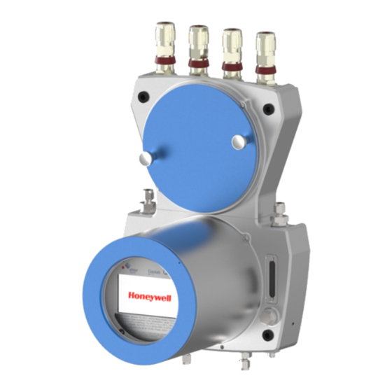
3 Structure and inscriptions of GasLab Q2 GasLab Q2 is a compact device housed in a two-piece explosion-proof aluminum housing. The parts are mechanically and electrically connected. The measuring in- strument contains all parts required to fulfill the measuring task. The built- in additional housing heater and an integrated fan allow an operating temperature range from −25°C ≙... -
Page 45: Connection Section
Structure and inscriptions of GasLab Q2 3.1 Connection section The connection section is sub-divided into the following parts: Gas connections (inputs/outputs and breather) Electrical connections (cable inlet and connection circuit board) Fig. 3-2: Overview of connection section / connection points Gas connections (inlets / outlets and breathing elements) The gas connections are pipe fittings and are equipped by the manufacturer. - Page 46 Structure and inscriptions of GasLab Q2 particle filter and is only suitable for connecting particle-free gases. The gas outlets are located on the upper side of the lower housing part, i.e. in the middle of the device. On the right is the gas outlet for the vent gas from the measurement.
-
Page 47: Instrumentation Section
Structure and inscriptions of GasLab Q2 3.2 Instrumentation section The instrumentation section contains gas-carrying and measurement components. These include the double- block- and- bleed valve block (DBB) for gas channel switching as well as the sensor block with pressure control and sensors, see also 4.1 Description of the measuring method (p. 55). - Page 48 If the ball is within the marks, there is enough flow for operation. A gas flow already exists even with stationary balls. Honeywell recommends the use of an additional flow meter in the gas path in cases where the exact flow rate is critical. (This can be removed...
-
Page 49: Human-Machine Interface (Hmi)
Structure and inscriptions of GasLab Q2 3.3 Human-machine interface (HMI) Fig. 3-4: Example of interactive display/operation panel The actual interface to the human operator, the human-machine interface (HMI), essentially consists of an interactive display behind a glass window, also called operation panel, and two status LEDs that indicate the status of the device. -
Page 50: Type Labels And Setting Marks
Structure and inscriptions of GasLab Q2 3.4 Type labels and setting marks The main type label with the most important information is located below the in- teractive screen, behind the inspection window. If the type label is covered by the sand guard, this information can also be read off an additional type label on the out- side of the housing. - Page 51 Structure and inscriptions of GasLab Q2 In addition, the type labels contain information about the approvals granted and the explosion protection properties. Not all certificates and approvals are listed in this documentation. The following table shows a selection. Approvals (selection) Only the specifications on the respective device apply! (For Approval number...
- Page 52 Structure and inscriptions of GasLab Q2 Fig. 3-7: Engraved device Information Explosion protection markings (explan- ation) Explication des marquages de pro- tection contre les explosions Icons / symbols Meaning / Signification Icônes / symboles Designations around these symbols (on the nameplate) indicate the area of application taking explosion protection into account.
- Page 53 Structure and inscriptions of GasLab Q2 Used Shorthand Description / Explanation / Explication Raccourci utilisé Ex marking complete device suitable for ex- zone 1 and 2 (gases/vapors) Marquage Ex appareil complet adapté pour les zones Ex 1 et 2 (gaz/vapeurs) Ex zones Potentially explosive areas are divided into zones according to the fre- quency and duration of occurrence of hazardous explosive atmospheres.
- Page 54 Structure and inscriptions of GasLab Q2 Used Shorthand Description / Explanation / Explication Raccourci utilisé Ex marking of Temperature class (in this case 135°C) Marquage Ex de la classe de température (dans ce cas, 135°C) The maximum surface temperature of the device must always be lower than the ig- nition temperature of the explosive mixture.
-
Page 55: Measuring Method And Measuring Point
4 Measuring method and measuring point In the analysis mode, the gases are measured in a continuous flow every second and the calculations of the gas composition are updated. The measured values can be displayed on site and forwarded to a control room, for example. The application is described and explained in detail in the sections 7 GasLab Q2 operation panel and operation (p. ... - Page 56 Measuring method and measuring point The physical measurement is carried out in the instrumentation section with the aid of a sensor block containing the electronics for the complete control, regulation, measurement acquisition and transmission. A two-channel double block and bleed valve block (DBB) supplies the gases to the sensor block.
-
Page 57: Measuring Point Overview
Measuring method and measuring point 4.2 Measuring point overview A typical measurement point consists of a sampling line from the gas pipeline to the measurement device. The stream of gas is measured quickly and continuously and then fed into the vent (waste) gas. If the pipeline pressure is higher than the maximum inlet pressure of the GasLab Q2, a pressure reduction system must be in- stalled and adjusted upstream of the process gas inlet. -
Page 58: Gaslab Q2 After Delivery And At The Place Of Use
5 GasLab Q2 after delivery and at the place of use This section gives an overview of how to handle the device before, during and after installation at the place of use. NOTICE AVIS Improper device handling (storage/ transport/ assembly) Manipulation incorrecte de l'appareil (stockage/ transport/ montage) Malfunctions and damage of the device are possible! Des dysfonctionnements et des dommages de l'appareil sont possibles ! -
Page 59: Storing Gaslab Q2
GasLab Q2 after delivery and at the place of use 5.1 Storing GasLab Q2 Prerequisite(s) The environmental specifications listed in the device data sheet are complied with. The packages are stored packed in closed, clean and dry rooms. Mechanical shocks (vibrations) do not occur during storage. During storage, the device is not connected to the power supply. -
Page 60: Transporting Gaslab Q2
3. Slowly bring the device to room temperature. 4. Open the device 5.5.1 Opening GasLab Q2 (p. 70) and let it dry for at least ➪ 12 hours. If necessary, contact Honeywell. GasLab Q2 User Manual (N ) 60 of 315... -
Page 61: Mechanical Installation Gaslab Q2
GasLab Q2 after delivery and at the place of use 5.3 Mechanical installation GasLab Q2 PROHIBITION INTERDICTION Carry out any of the work mentioned in this section if you do not have Effectuer l'un des travaux mentionnés dans cette section si vous ne possédez pas the necessary instructions from the manufacturer or his rep- resentatives! -
Page 62: Place Of Use And Installation
The sand guard (HMI cover) should be screwed on in sandy en- vironments. Contact Honeywell for further information. The meter weighs approximately. 16 kg ≙ 36 lb . Before mounting, make sure that the mounting surface has the sufficient stability. - Page 63 GasLab Q2 after delivery and at the place of use GasLab Q2 must be installed so that the main breather element points down- wards and the cable connections point upwards. GasLab Q2 does not require a special mounting plate since the measurement device contains all the parts required for the measuring task in its explosion-pro- tected housing.
-
Page 64: Device Dimensions
GasLab Q2 after delivery and at the place of use 5.3.2 Device dimensions Please note all dimensions are given metric and in mm. 1 mm = 0.03937" NPT adapters are available for the threads The dimensions with information (1 (2 (3 depend on the types of fluid and electrical couplings used. -
Page 65: Fluidic Installation Of The Measuring Device
GasLab Q2 after delivery and at the place of use 5.4 Fluidic installation of the measuring device For all work described in the following, the recognized rules of technology for hand- ling high purity gases and the piping plans drawn up and specified by the plant op- erator must be observed. -
Page 66: Fluid Interfaces
GasLab Q2 after delivery and at the place of use 5.4.1 Fluid interfaces GasLab Q2 has 2 gas inlets and two gas outlets, each of which is protected by a flame arrester. Two breathing points are used to enable atmospheric pressure equal- isation between the inside of the device and the environment. -
Page 67: Connect The Vent Gas Line
The vent line must be laid separately, at least 1m ≙ 3.28ft (3 m≙ 9.84ft re- commended). If the bypass has a high flow rate, it should preferably be equipped with a separate vent (waste) gas line to prevent return effects. Contact Honeywell in case of deviating exhaust gas conditions. - Page 68 GasLab Q2 after delivery and at the place of use Since no tightness test can be carried out when the device is switched off, the vent line must be checked for leaks with a gas leak detector immediately after com- missioning.
-
Page 69: Connect The Process Gas Line
GasLab Q2 after delivery and at the place of use 5.4.3 Connect the process gas line Prerequisite: The process gas from the process line (pipeline) is provided according to specification via the tapping equipment with temperature equalization system and pressure regulator. Refer to 11.3 List of suitable gases and calibration gases (p. 288) -
Page 70: Connect/Replace Calibration-, Verification- Gas Cylinders
), , must be connected to the instrument for this purpose. A suitable pressure reducer is required for this purpose, if not already avail- able. Honeywell offers prefabricated panels with the high pressure reducers for this purpose. Some situations make it necessary to connect additional gas cylinders, e.g. a veri- fication measurement or service calibration. - Page 71 GasLab Q2 after delivery and at the place of use Prerequisite(s) Permission and consent from the system operator to open installed equip- ment is available in writing. Expolsive atmosphere is not present. Voltage is switched off. Conditions according to ISO / IEC61010-1 are given. An authorized person (calibration officer) is present if required by the reg- ulations of your country, and the measurement task of the instrument.
-
Page 72: Closing The Housing Of Gaslab Q2
GasLab Q2 after delivery and at the place of use 5.5.2 Closing the housing of Gaslab Q2 Prerequisite(s) Work on the opened device has been completed. An authorized person (calibration officer) is present if the regulations of your country and the measuring task of the device require this. Device as well as sensor and signal lines are sealed according to the condi- tions of the applicable authorization, if necessary, e.g. -
Page 73: Securing The Detachable Parts For Opening The Housing
GasLab Q2 after delivery and at the place of use 5.5.3 Securing the detachable parts for opening the housing All parts that can be unscrewed to open the housing are protected against un- intentional opening by locking screws. To open / unscrew, screw the locking screws shown in the following figure into the basic housing Fig. -
Page 74: Electrical Installation
GasLab Q2 after delivery and at the place of use 5.6 Electrical installation Before starting work, make sure that you observe the general safety rules. Also ob- serve and follow the information in section 2 Safety information (EN-US-FRA) ➪ (p. 16) . Especially in potentially explosive atmospheres use a gas leak detector when working on the device and make sure that it is voltage-free (supply and sig- nals) before any change of the wiring. -
Page 75: Power Supply And Electric Protection
GasLab Q2 after delivery and at the place of use The device is protected against polarity reversal. The device will not work if the connections have been reversed. 5.6.1 Power supply and electric protection The power supply must comply with section 2.7 Electrical safety information ➪ ... -
Page 76: Cables (Power Supply / Communication)
GasLab Q2 after delivery and at the place of use 5.6.2 Cables (power supply / communication) For the connection between the instrument and other instruments different control and signal cables are suitable, the choice depends on the requirements at the place of use. -
Page 77: Grounding And Potential Equalisation
GasLab Q2 after delivery and at the place of use 5.6.3 Grounding and potential equalisation DANGER due to inadequate grounding of the device DANGER en raison d'une mise à la terre inadéquate de l'appareil. Unsafe situations can arise electric shock is possible. Des situations dangereuses peuvent survenir ;... -
Page 78: Cable Glands (Adapter / Dummy Plugs)
GasLab Q2 after delivery and at the place of use 5.6.4 Cable glands (adapter / dummy plugs) On the upper side of the Q2 are four threaded holes with M20x1.5 thread. These can be fitted as required. Possible are dummy plugs, adapters (½"NPT thread) or cable glands like shown in the example below. - Page 79 (24 V DC). The remaining holes provide access for further signal cables if required. Select a suitable type of cable gland depending on the loc- ation and requirements, contact Honeywell if necessary. In order to maintain the specified explosion protection, the screw-in parts must be installed and cast in accordance with the gland manufacturer's specifications.
- Page 80 GasLab Q2 after delivery and at the place of use The required accessories listed below are supplied in the recommended or ordered version. * High number of cores for ATEX and IECEx only; low number of cores for all other certificates ** To comply with the specified explosion protection, the cable gland must be sealed as specified by the cable gland manufacturer Alternativ screw-in parts for use in Japan...
-
Page 81: Electrical Connection Diagram And Electrical Interfaces (Inputs And Outputs)
GasLab Q2 after delivery and at the place of use 5.6.5 Electrical connection diagram and electrical interfaces (inputs and outputs) The cables are connected to the board in the connection box via the plugs on the edge of the board. All electrical interfaces (galvanically isolated) are located here. The plugs are secured with snap-in hooks. - Page 82 GasLab Q2 after delivery and at the place of use Fig. 5-6: Electrical connection assignment (circuit board) GasLab Q2 User Manual (N ) 82 of 315...
-
Page 83: Connection To Other Devices And System Parts
GasLab Q2 after delivery and at the place of use 5.6.6 Connection to other devices and system parts The connection diagrams for sensors and devices to which the instrument can be connected are shown in example form in the following. This may require special parameterization in enSuite. - Page 84 GasLab Q2 after delivery and at the place of use CAUTION Violation of explosion protection ATTENTION Violation de la protection contre les explosions Risk of explosion Risque d'explosion In order to comply with the specified explosion protection level, the cable connection in the gland must always obey the gland manufacturer’s spe- cifications.The isolation or surge (lightning) protection on the cables must be installed by the user, depending on the situation of use.
- Page 85 GasLab Q2 after delivery and at the place of use Ethernet connection Ethernet can be used to connect to the device, access the remote con- trol panel, retrieve information, send a new set of parameters to the device and start other device actions. It is best to have an Ethernet cable pulled to a location outside the haz- ardous area, ending in a plug for RJ-45: This way you or a service person can always connect a laptop to the device.
- Page 86 GasLab Q2 after delivery and at the place of use Fig. 5-7: Sample LAN/Ethernet connection (diagram) Additional to the wiring, settings must be made before this interface can be used. See sections 7.3.9 System display I/O (network settings / in- ➪...
- Page 87 GasLab Q2 after delivery and at the place of use RS485 serial interface connection Connections include, for example, other measurement devices, devices for final pro- cessing and evaluation, PLC systems, and so on. Cable type refer to section 5.6.2 ➪ Cables (power supply / communication) (p. 76).
- Page 88 GasLab Q2 after delivery and at the place of use Digital inputs There are two electrically isolated inputs supplied in the connection box (TB5-ter- minals 1 to 2 and TB5-terminals 3 to 4, details see figure). The maximum supply voltage is approx. 9 V. For cable type refer to section 5.6.2 Cables (power supply / communication) ➪...
- Page 89 GasLab Q2 after delivery and at the place of use Digital outputs There are four digital outputs (electrically isolated passive output circuits) in the connection box (TB6-terminals, details see figure). The output at TB6-5 is a breaker (NC, “normally closed”), the other outputs are makers (NO, “normally open”).
- Page 90 GasLab Q2 after delivery and at the place of use Analog outputs There are four common electrically isolated active output circuits (“common ground”/short-circuit-resistant) with 0 or 4 to 20 mA in the connection box (TB7- terminals, details see next figure). The maximum supply voltage is around 9 V. The maximum load is 390 Ω...
-
Page 91: Electrical Device Test To Verify Correct Installation
GasLab Q2 after delivery and at the place of use 5.6.7 Electrical device test to verify correct installation After completion of the electrical work, you should conduct a test to eliminate the possibility of errors, e.g. insulation faults in the supply voltage and communication. PROHIBITION INTERDICTION to conduct the tests in a potentially explosive atmosphere. -
Page 92: Commissioning And Decommissioning
The commissioning procedure may only be carried out by qualified technician or field service personnel. Honeywell can provide training and commissioning services. Before commissioning, make sure that Section 2 Safety information (EN-US- ➪... -
Page 93: Commissioning Preparations And Requirements
There is no moisture condensation inside the device. If in doubt, remove the covers (see next section) and allow the appliance to dry for at least 12 hours; or contact Honeywell. Power supply and communications are carried out properly and is available. -
Page 94: Set Password For Administrator (Admin1) And Generate A New Tls Certificate
6.1.2 Set password for Administrator (admin1) and generate a new TLS certificate Background The access data is always checked in the device, i.e. the user must have been cre- ated in the device. In the delivery state, user passwords for standard users are empty for all enCore devices, including admin1. -
Page 95: Adapting The Factory Parameterization
6.1.3 Adapting the factory parameterization In the factory parameterization (default parameter set), usually only calibration gas properties, automatic calibration intervals and the purging / flushing times for the gases must be adjusted. For extreme ambient conditions, the setting for the aux- iliary housing heater or the fan is still required. -
Page 96: The Hardware Parameter Guard (Ssw)
6.1.4 The hardware parameter guard (SSW) You can (and must for fiscal use) protect settings which affect the measuring properties. This is done with the Security Switch (short: SSW) also called calibration switch. It ensures that fiscally relevant changes can only be made with the SSW opened or are logged in the audit trail. - Page 97 Commissioning and decommissioning Steps The SSW connection pins can be found on the underside of the main board (Q2BASE) between the battery and the USB connector. Close SSW 1. Insert the jumper using angled tweezers or pliers. 2. Use a mirror to check the correct positioning. Compare the following figure. Fig.
-
Page 98: Additional Conditions For Fiscal Metering
Commissioning and decommissioning 6.1.5 Additional conditions for fiscal metering In the case of fiscal use, the conditions laid down in the relevant approval must be met. This is ensured by a file in the device that adjusts the settings. For final com- missioning, the calibration switch or security switch (SSW) must be closed. -
Page 99: Standard Commissioning And Normal Operation
Commissioning and decommissioning 6.2 Standard commissioning and normal opera- tion Step Action: Commissioning Check the state of the system and the connections. Open the operational calibration gas cylinder (setting 0.2 MPag ≙2 barg≙29.01psig) Open the process gas (PG) (setting from 0.15 MPag ≙1.5 barg ≙21.76psig to 0.3 MPag ≙3 barg ≙43.51psig = max. -
Page 100: Checking The Setting And Signals
Commissioning and decommissioning 6.2.1 Checking the setting and signals Adjustment of the gas flow is only necessary if the right LED of the device flashes red. This can be due to local installation conditions or the use of the bypass and in- dicates that the internal pressure is too low. -
Page 101: Decommissioning And Disposal
Commissioning and decommissioning 6.3 Decommissioning and disposal 6.3.1 Decommissioning and disassembly WARNING! Risk of explosion AVERTISSEMENT ! Risque d'explosion DO NOT OPEN WHEN AN EXPLOSIVE ATMOSPHERE IS PRESENT NE PAS OUVRIR EN PRÉSENCE D'UNE ATMOSPHÈRE EXPLOSIVE For safety reasons, the decommissioning of the enCore device may only be performed by the service or appropriately trained specialist personnel of the operator. - Page 102 Commissioning and decommissioning To take the enCore device out of operation, proceed as follows: 1. Disconnect the device from the power supply. 2. Turn off all gas flows and depressurize all gas inlets. 3. Here, too, prevent the unintentional opening of the shut-off valves by taking suit- able measures so that no danger can arise from further disassembly.
-
Page 103: Disposal
WEEE directive into national legislation in different ways, the regulations for the return of disused equipment vary. Please ask your local Honeywell sales partner how the take-back of your equipment is regulated. Environmentally friendly disposal according to WEEE directive The WEEE directive 2012/19/EU was issued by the European Com- mission. -
Page 104: Gaslab Q2 Operation Panel And Operation
Changes which have been completed but not yet saved are discarded when you log out. Honeywell can provide classes and training to make the measuring equipment easier for you to use and for using all the individual options offered by the device. If you are interested, please contact 12.1 Tech-... -
Page 105: Leds On The Operation Panel
7.1 LEDs on the operation panel Two multicolored LEDs are placed on the device above the actual screen. On the left the power LED and on the right the status LED. Their color and behavior (steady light or flashing light) indicate whether the measuring device is working properly or whether there is or was a malfunction. -
Page 106: Screen Display On The Operation Panel
7.2 Screen display on the operation panel The display of the control panel, is equipped with 7 touch fields, for interactions. Shown as red areas in the following figure, the areas are not visible on the operation panel. Fig. 7-1: Interactive screen The display lighting is switched off automatically after a period of in- activity, whose length is adjustable. -
Page 107: Superimposition Keys
7.2.1 Superimposition keys If you move your finger over the touch fields of the display on the device or if you click on them with the mouse in the remote operation panel, direction arrows will be displayed pointing left and right, as well as up and down. A confirmation arrow will appear at the bottom of the display. -
Page 108: Different Types Of Device Displays
GasLab Q2 operation panel and operation 7.2.2 Different types of device displays Main display is the name of the first display of an application or a functionality of the basic system; it shows the most important results of this functionality. Depending on the application or functionality, further information is displayed in subordinate device displays. -
Page 109: Navigation Options
GasLab Q2 operation panel and operation 7.2.3 Navigation options In general Two buttons are displayed at the bottom of the touch screen. Depending on the context, you can use the symbols , as well as or Function of the buttons switches directly to the home display. -
Page 110: The Middle Of The Bottom Status Line
6.1.4 The hardware parameter guard (SSW) ➪ (p. 96). You can also have a seal affixed to the switch its selve to verify unauthorized access. Contact Honeywell if necessary. If the symbol is shown, somebody has logged in and is working with the device. -
Page 111: Visibility Of The Displays
GasLab Q2 operation panel and operation Options at a glance: means that the security switch (SSW) is open. means that the user is logged in. One or more remote controls are active. The local user sees the screen content and can operate the device . The device is operated remotely. -
Page 112: Entries And Changes Using The Operation Panel
GasLab Q2 operation panel and operation 7.2.6 Entries and changes using the operation panel Changes on the device are always made in the following steps: Log into the device Complete and confirm the changes on the device Log out of the device Use the Users main display to log in, confirm and log out 7.3.6 System display ➪... - Page 113 GasLab Q2 operation panel and operation If you have confirmed the selection, you also must execute your change. In the above example, this is the action Update date and time. which is then underlined. Changes using a displayed keypad for entering letters and numbers. To prevent local users from inadvertently blocking remote access, the virtual keyboard closes automatically after one minute of inactivity - no input is visible on the remote opera- tion panel.
- Page 114 GasLab Q2 operation panel and operation If only individual characters are to be replaced, it is possible to jump to the end of the existing entry using the key and then supplement the entry. At the same time, the key changes and shows the following symbol which allows individual characters to be deleted starting from the right.
-
Page 115: Displays And Functions
GasLab Q2 operation panel and operation 7.3 Displays and functions Although the Q2 main display contains all the relevant information, some appli- cations require you to change the display. You can get to any display using the nav- igation methods explained in the previous section. In addition, device dialogs and confirmation prompts guide you through the displays. - Page 116 GasLab Q2 operation panel and operation Fig. 7-9: "Home” display node (example) If you have the required rights, you can change and supplement this display. Define basic display and edit display behavior (p. 200) ➪ The following describes only the contents of the “Home” display that are usual on delivery.
- Page 117 Home display (device language change) Up to two languages are optional possible. English is always the second language. The devices will always start in the first language. Please notify Honeywell if you wish to change the first language installed in the device.
-
Page 118: Info Display (Overview)
GasLab Q2 operation panel and operation 7.3.2 Info display (overview) This symbol opens the following display: The display shows the device’s serial number (first line) and the status of the security switch (SSW). Furthermore, the display provides access to the listed func- tions: Fig. - Page 119 GasLab Q2 operation panel and operation The link Certificate on the display enables to view the MMS certificate for secure data transmission. The display action Delete certificate allows the authorized user to delete the existing certificate and create a new one. Fig.
- Page 120 GasLab Q2 operation panel and operation Fig. 7-14: Display Certificate with certificate information, end of page - example Naming convention according to X.500 standard and values for TLS certificates for enCore devices: CN = Common Name, here: enCore device type C = Country;...
- Page 121 GasLab Q2 operation panel and operation Fig. 7-15: System info – Device monitor display Device monitor Operating hours Elapsed hours that the unit has been on and running since manufacture. Remaining battery charge in percent. Battery (The battery is mainly used when the instrument is switched off. The state of charge message "Battery charge low!"...
- Page 122 GasLab Q2 operation panel and operation Info display (Software Status) Software status shows the identification data of all software parts in the device. The data consist of the name of the software parts, the version number and the checksum. In addition to the “Last check”, the topmost line contains the date of the readout for the following information.
- Page 123 8.2.6 Fiscal parameters and optional using of approval file ➪ (p. 219). If necessary, contact Honeywell. If an approval file is used and both the official access rights of the para- meterization as well as the fiscal software component versions are in line with the approval file, then this text is black;...
- Page 124 GasLab Q2 operation panel and operation Info display (Display test) Using the display test, you can check whether the device display is working cor- rectly. Not all enCore devices have a display. Prerequisite(s) Home display is shown, switch to this display with if necessary.
-
Page 125: Error List - Main Display (Accept / Quit Error Messages)
GasLab Q2 operation panel and operation 7.3.3 Error List – Main display (accept / quit error messages) The device manages the warning and alarm messages in the error list (located on Home display) and reports them in the logbook. Which messages appear, depends on the parameterization of the device. - Page 126 If required, repeat these steps for other lists. After all the entries have been accepted, the system will be returned to error-free status. The status LED will be lit in green. Honeywell provides assistance with troubleshooting work. 12.1 ➪ ...
-
Page 127: System Display (Overview)
GasLab Q2 operation panel and operation 7.3.4 System display (overview) The system display, a node to additional displays, is opened by se- lecting this symbol. You can go to the following sub-displays using this node: Tim Service 7.3.5 System display Time Service (System time and date) ➪ ... -
Page 128: System Display Time Service (System Time And Date)
GasLab Q2 operation panel and operation 7.3.5 System display Time Service (System time and date) Depending on the parameterization, the Time Service has up to four standard displays located behind this symbol. The Main display showing the internal time in the device, via links and ac- tions it leads to the other possible and optional displays. - Page 129 GasLab Q2 operation panel and operation The system time (permanent device- internal calendar with date and time) is saved on a battery-buffered clock block and available even after the device has been switched off and on again. Changing the system time is the generic term for both synchronization and for adjusting the date and time.
- Page 130 GasLab Q2 operation panel and operation Synchronizing system time For a user who is not logged in or a user who is logged in but is not entitled to change the device time, “ Time Service – Time Synchronization” will open as the second display after “Date &...
- Page 131 GasLab Q2 operation panel and operation "Update date and time" For a user who is logged in and entitled to change the device time, after “Date & Time” has been activated, the display with the same name will open as the second display.
- Page 132 GasLab Q2 operation panel and operation NTP overview display The final optional display entitled NTP overview is only displayed if NTP syn- chronization has been enabled in the device. Therefore it has to be parameterized in enSuite branch Basic System – Time Service, parameter NTP, see online help for more information.
- Page 133 GasLab Q2 operation panel and operation Name resolution error The names of the NTP servers (Server 1..Server 3) could not be resolved via DNS. Possible causes: The DNS server is not available, e.g. because the IP address of the DNS server in the network settings (CPU or ESER4) is not cor- rectly parameterized.
-
Page 134: System Display Users (Login, Logout, Password)
GasLab Q2 operation panel and operation 7.3.6 System display Users (login, logout, password) The user management only has one pre-defined display (Main display) for logging in and out of the device as users and rights are managed in enSuite. After a successful local login, the actions to accept or discard the parameter changes and to log out are displayed. - Page 135 GasLab Q2 operation panel and operation Login Access: Home – System – User Only one user can be logged in to the device exclusively at any one time, either the action Login will be displayed on Users Main displayor the user name through which the action is logged.
- Page 136 GasLab Q2 operation panel and operation Mechanisms to end exclusive access The device has the following mechanisms to prevent the device accidentally being blocked for further service activities: Parameter Inactivity timeout If there is inactivity, a user is automatically logged out after a parameterized timeout (default is 120 ...
- Page 137 GasLab Q2 operation panel and operation End your session with Logout. The session is over. Other users can log in to the device. Always log out of the device manually as soon as you have made the desired changes. On the one hand, this prevents the device from unnecessarily being blocked for service activities of other users and on the other hand it prevents other users from using your session to make changes to the device with your user data.
- Page 138 GasLab Q2 operation panel and operation Change password All users can change their passwords on Users Main display after successfully logging in to the device. Logout (p. 136) ➪ Click the action . The fields for the new password will be dis- Change password played: Fig.
- Page 139 GasLab Q2 operation panel and operation Unlock Password Lock for Older Devices Until early 2019, devices were shipped with a Honeywell Administrator password. Since the administrator rights are transferred to the system operator, the factory-as- signed administrator password must be reset for older devices.
-
Page 140: System Display (Logbook)
GasLab Q2 operation panel and operation 7.3.7 System display (Logbook) The Logbook located under Home System Logbook is one of two device logs in which events during operation are stored as history. It is similar to an archive; each entry is assigned an ordinal number. The entries which have been re- moved from the error list 7.3.3 Error List –... -
Page 141: System Display (Audit Trail)
GasLab Q2 operation panel and operation 7.3.8 System display (Audit trail) The Audit trail is one of two device logs in which events during operation are stored as history. It is located under Home System Audit trail. The content is also stored in the other log. - Page 142 GasLab Q2 operation panel and operation Fiscal audit trail The fiscal audit trail has the same structure as the general audit trail and is therefore not described in any further detail here For the enCore FC device series, you will find a detailed description in enCore manual “Instructions for Use in Legal Metrology“...
- Page 143 GasLab Q2 operation panel and operation Audit trail entries The audit trail has space for 1000 entries. In the general section, the oldest entry will be overwritten after 1000 entries have been created. If this space is occupied in the fiscal section, no changes can made to the legally relevant parameters without opening the security switch (SSW).
-
Page 144: System Display I/O (Network Settings / Inputs/ Outputs)
GasLab Q2 operation panel and operation 7.3.9 System display I/O (network settings / inputs/ outputs) The I/O – Overview display lists all the device parts available on inputs or out- puts and enables the user to go to other sub-displays using hyperlinks. The hyperlinks and test mode function appear depending on the parameter set. - Page 145 GasLab Q2 operation panel and operation If a user with the appropriate authorization is logged in, the configuration (DHCP mode), IP address, network mask, default gateway, DNS server, TCP ports and host name can be changed. The number of entries which can be changed is also af- fected by the selected / pre-set settings.
-
Page 146: Display Q2 Sensor Values
GasLab Q2 operation panel and operation 7.3.10 Display Q2 sensor values Behind this symbol lies the list of sensor values. As a rule, this display is only used for service purposes and to isolate faults. Fig. 7-35: Q2 sensor values display A complete list of all sensor values is displayed in the following table: Sensor signal Use/Meaning... -
Page 147: Display Q2 Control (Calibration/Verification/Touch)
(p. 167), ➪ Displays and functions for " Base calibration " are not described here (basse calibration only takes place before delivery at the Honeywell factory) The Calibration data display lists internal instrument values and deviations from previous settings caused by the operating calibration... - Page 148 GasLab Q2 operation panel and operation Fig. 7-37: Q2 – Calibration data (Sub-display of Calibartion display) The display of the calibration values is not required in everyday operation. It is for service purposes only and may help troubleshooting work. In the Gas components displays you can view the gas composition of all cal- ibration gases used.
-
Page 149: Q2 Main Display (Calculation Standard)
GasLab Q2 operation panel and operation 7.3.12 Q2 main display (calculation standard) This symbol takes you to the Q2 main display (display when the devices started set at the factory). Alter- natively, you can use the button (home display bottom right) * The button will take you to the parameterized basic display, in delivery condition, this is the main display. - Page 150 GasLab Q2 operation panel and operation Fig. 7-40: Q2 main display (default parameter set) The operating mode is specified under the name of the display next to “Operation”. The user can adopt for operating modes. The current step being undertaken by the device is shown next to “Step”.
- Page 151 GasLab Q2 operation panel and operation These only occur during the base calibration at the factory, during Honeywell ser- vice work or in the event of errors and are therefore not described in further detail here. Operation Step Meaning Idle (0)
- Page 152 GasLab Q2 operation panel and operation Activate the link using the superimposition keys, this will change the display as fol- lows: Text Main display changes to Standard B, and indicates that the figure to the side is displaying results using standard B. In the middle of the second line the standard B with the standard states is now named in the example, it is ASTM 3588 14.696 psia.
- Page 153 GasLab Q2 operation panel and operation Displayed value Meaning (of the value abbreviation)/Physical quantity (abbreviation) Displayed result in mol% Isobutane (i-butane) n-pentane Isopentane (i-pentane) Hexane Total heptane Total octane Total nonane Total decane Total of all hydrocarbons ∑ ethane + all higher hydrocarbons Hexane Σ...
- Page 154 GasLab Q2 operation panel and operation The superior/inferior calorific value changes if the gas contains water va- por.Depending on the quantity, a distinction is made between dry and partially saturated or saturated (humid). Values for the partly saturated or humid gas are lower than for dry gas since water vapor and combustion gas components divide the volume.
-
Page 155: Display User Archives
GasLab Q2 operation panel and operation 7.3.13 Display User archives This symbol takes you to the main display of the User Archives AFB, which can be used by multiple devices, in other words, also by the GasLab Q2. The following figures and explanations are only examples, further information and the actual set-up takes place using enSuite. - Page 156 GasLab Q2 operation panel and operation Fig. 7-44: Values sub-display It is also possible to delete the content of the archive. A login with the appropriate rights is required for this. The archive can be cleared if the Delete content link is underlined, see the two ex- amples Fig.
-
Page 157: Display Modbus
GasLab Q2 operation panel and operation 7.3.14 Display Modbus This symbol takes you to the main display of the Modbus AFB which can be used by most enCore devices and also by the GasLab Q2 The following figures and explanations are only examples, further information and the actual set- up takes place using 8 Configuration and analysis software ➪... - Page 158 GasLab Q2 operation panel and operation "Main display" Fig. 7-47: Modbus Main display – example For Modbus master or client the dropdown list contains all parameterized Remote devices; for slave or server only the entry Local device is available The text No filters selected is displayed in case no filter from the display Modbus filter is active;...
- Page 159 GasLab Q2 operation panel and operation Display "Modbus filter" Fig. 7-48: Display Modbus filter – example GasLab Q2 User Manual (N ) 159 of 315...
- Page 160 GasLab Q2 operation panel and operation Display "Diagnostic" This display provides diagnostic information of the selected area (not from function diagnostics 0x08 ): Fig. 7-49: Display Diagnostic – example Error counters are only displayed, if they are not null ( 0 ), max. value is 999.999.999. Following error counters are supported: All Modbus types: Access error...
- Page 161 GasLab Q2 operation panel and operation Client and master: Error responses Received telegram(s) with error response Checksum error (master only) Received telegram(s) with wrong checksum Header error Telegram(s) with unexpected function or (master only) unexpected command Reception timeout Response time is up. ID error (master only) Received telegram(s) with wrong ID Register not found...
- Page 162 GasLab Q2 operation panel and operation Display "Modbus register" Fig. 7-50: Display Modbus register – example The test mode is available for all export registers except the data types Export date and time, Monoflop register and Sequence number (for archive areas). The user right Change general system settings is required.
- Page 163 GasLab Q2 operation panel and operation Steps in enSuite Prerequisite(s) You are logged in as a user with the user right Change general system settings. To activate the test of an export register, ..switch to the detailed display of the desired export register via Modbus – Main display.
-
Page 164: Operation And Operating Modes Of Gaslab Q2
GasLab Q2 operation panel and operation 7.4 Operation and operating modes of GasLab The aim of this section is to explain more details of operation, operating modes and device functions. First of all, the observation of the device functions and normal operation are presented, which requires no or little action from the operating per- sonnel. -
Page 165: Operating Mode: Operational Calibration (Manual)
GasLab Q2 operation panel and operation 7.4.2 Operating mode: Operational calibration (manual) The last valid gas property values are held throughout the calibration time using measurement outputs. The parameters from the last successful calibration remain in use until a new successful cal- ibration has taken place. - Page 166 "Analysis" is executed again. This can be recognized by the status line. If possible correct the error and repeat the process, otherwise contact Honeywell. An operational calibration can also be triggered automatically 8.4.1 ➪...
-
Page 167: Operating Mode: Verification (Special Mode)
GasLab Q2 operation panel and operation 7.4.3 Operating mode: Verification (special mode) This operating mode can be used for device control. Manual - - similar to the operational calibration in the previous section - - or automatic execution are possible, see 8.4.1 Setting or changing automatic measurements (p. 236). - Page 168 GasLab Q2 operation panel and operation Steps 1. Activate on the device or in the remote operation panel (Home-> Q2 Control) 2. Activate “References”. Check whether the test gas mixture entered corres- ponds to the one used, if not, adjust it. 7.2.6 Entries and changes using the ➪...
- Page 169 GasLab Q2 operation panel and operation 7. After successfully connecting the gas, acknowledge the security query from step 4 with "Confirm" (or cancel the process with "Cancel").After confirmation, the device will be flushed with the test gas and then the measurement will be started.
- Page 170 GasLab Q2 operation panel and operation 9. You will be requested to restore the original gas connection. (The message “Prepare process gas” will appear depending on the actual input used. See figure) 10. Restore the original connection correctly. Obey all the safety information for working on gas connections.
-
Page 171: Configuration And Analysis Software Ensuite
Honeywell offers courses and training to help you learn how to use the meters and take advantage of all the individual capabilities the in- strument offers. If you are interested, please contact Honeywell 12.1... -
Page 172: Ensuite Basis Of Use
Install and uninstall enSuite You can download the installation program from the Software Downloads section of the website: process.honeywell.com/us/en/site/elster-instromet/ support#software-downloads This site also contains a file describing the installation procedure and the minimum system requirements. Complete the installation as specified on the website. Ensure that there are no special characters in the file path, otherwise it will not be possible to transfer files to a device. - Page 173 Starting enSuite Start enSuite either via the enSuite program symbol on the desktop or via the Start menu (Elster group of programs). Fig. 8-1: Welcome window The software’s user interface will appear once it has been opened. At the top, there is the menu bar and below it is the button bar.
- Page 174 Configuration and analysis software enSuite More information about the interface is provided in the online help. enSuite online help (p. 175) ➪ It is possible to detach some windows or window areas from enSuite and display them separately. Open the context menu in the header or tab of the area you want to detach and se- lect "Float"...
- Page 175 Configuration and analysis software enSuite enSuite online help Please use the online help to get an overview of the enSuite basic functions. You will find instructions on how to use the software and on basic settings as well as information on the parameters to be changed. The manual supplements the information if necessary.
-
Page 176: Data Connection To The Measuring Device
Configuration and analysis software enSuite 8.1.2 Data connection to the measuring device Connection options A data connection between computer and device can be established either directly via a USB cable or via TCP/IP computer network. The communication between enCore device and enSuite is carried out via MMS and is secured via TLS since Basic System 03-39. - Page 177 Configuration and analysis software enSuite Since Windows 10, enSuite can communicate with the enCore device via USB without driver installation, use always current Software versions. You may need to change the Windows USB energy saving settings for USB connections between notebooks and enCore devices if problems occur when connected, since in particular mobile devices are designed to use as little energy as possible.
- Page 178 Configuration and analysis software enSuite Fig. 8-4: Dialogs to select the connection – example To establish a USB connection, select Local connection; to establish a TCP-IP connection, select Remote connection – in this case, the network name or IP address of the enCore device is required, adjust the default ports if necessary. Confirm with [OK].
- Page 179 Configuration and analysis software enSuite Fig. 8-5: Certificate is still unknown – example first connection establishment Check the validity of the certificate. You have the following options: Check certificate on site directly on the device: Info – <device serial no.>, Certificate Open the certificate information via the basic display of the device: Info –...
- Page 180 Configuration and analysis software enSuite If you are unsure whether you trust the connection (e.g. because you are not on-site), select [Accept temporarily]. The current MMS connection will remain, but enSuite will not save the certificate. The next time a connection is estab- lished, a security query will appear again.
- Page 181 Configuration and analysis software enSuite Disconnecting the device There are two further options available to disconnect data connections: Symbol Action Description Disconnect from all devices Terminates all active connections. (alternatively press the [F4] key) Terminates the connection to the device which Disconnect is selected in the navigation window (identifi- cation via serial number).
-
Page 182: Saving And Managing The Device Setting
8.1.3 Saving and managing the device setting The following section explains how to read out and save and export the device para- meterization, the software structure of the device and the import of saved para- meterizations. Read-out parameterization NOTICE Data and function loss possible! There is no automatic backup of the parameterization in enSuite! Avoid data and function loss by reading out the parameterization after each change. - Page 183 Software modules of the parameterization GasLab Q2 is based on a Honeywell product platform called enCore. Both the hard- ware and software have a modular design. The device software of each enCore product consists of the following: The Basic System is responsible for functionalities (such as the I/O coupling or connection to digital protocol interfaces) and is a key component of the soft- ware for all enCore devices. ...
- Page 184 Configuration and analysis software enSuite Fig. 8-8: Navigation window and parametrization window exambles. After double-clicking on the file, enSuite opens the parameterization window (left part in the example) and displays the parameterization. The tree structure is dis- played next to the navigation window. The top level shows the device name; in the subordinate level you can see the Basic System and the AFBs.
- Page 185 Configuration and analysis software enSuite AFB configuration You can see the current parameter structure tree on the left-hand part of the para- meterization window. The root is for the device. The first sublevel consists of AFBs that are currently included. The Basic System is always included in the device soft- ware;...
- Page 186 Configuration and analysis software enSuite Fig. 8-10: Example of saved parameter set After double-clicking on the file (Backup in the example), enSuite will open the para- meterization window and show the parameter set. See the online help for more information about this window. Certain parameters are set to defined values as default.
- Page 187 This process should only be used when all other options have been ex- hausted, as the current settings in the device will be deleted. If you are in any doubt, contact Honeywell. GasLab Q2 User Manual (N )
-
Page 188: Update Downgrade And Bugfix-Software
Observe the notes on the web page and in the update instructions. Ac- cording to this, check whether the installed version meets the necessary requirements. If the software is out of date, update all parts. If in doubt, contact Honeywell or have Honeywell update the device. Website https://process.honeywell.com/us/en/site/elster- instromet/support contains the latest software releases which can be found in the Gas analyzers sub directory. - Page 189 Configuration and analysis software enSuite Fig. 8-13: Change of settings Select tap "Options" select option "Authorization" set check box as shown. Result:After reopening and repeat of the steps only green entries are shown GasLab Q2 User Manual (N ) 189 of 315...
-
Page 190: Changing Basic (System) Settings
Configuration and analysis software enSuite 8.2 Changing basic (system) settings The following section explains some SFB of the basic system and how to adjust their settings. An overview is given in the online help. Select Basic system in the parameter tree of the parameterization window and press [F1]. 8.2.1 SFB I/O (IP address network- and I/O- settings) - Page 191 Configuration and analysis software enSuite Ethernet settings For data communication, connections via Ethernet are mainly used. Go to para- meter branch: GasLab Q2 – Basic system – I/O – Board 0 : CPU . Fill in your changes, proceed like explained in the online help. Also note the information in sec- tion Ethernet connection (p. 85)
- Page 192 Configuration and analysis software enSuite Possible error: Current output does not react. Situation:After a parameterization, the outputs of the current outputs do not show the expected values. Cause:The output condition has been set to "Used" but in the following line no Output condition is selected (See picture line with flag Unassigned) Fig.
-
Page 193: System Settings
Configuration and analysis software enSuite 8.2.2 System settings In node System you can parameterize basic system settings. The following Function Blocks are summarized here for enCore devices: ⇒ General system settings ⇒ Error List ⇒ Audit trail ⇒... -
Page 194: Time Service Sfb Settings And System Time Action
Configuration and analysis software enSuite Path: <Device> - Basic system - Users – Special user rights tab Fig. 8-17: Störungen quittieren Benutzerrechte 8.2.3 Time service SFB settings and system time action Time Service is a System Function Block (SFB) of the Basic System. The following areas can be parameterized with the Time Service: General Daylight saving... - Page 195 Configuration and analysis software enSuite In the export value window SFB provides time related events under Basic system time service time events. They can be used as input signal for time-controlled ac- tions in other SFBs or AFBs. ) Special case: Trigger for a longer cycle duration is activated first Event signals in a second rhythm are formed relative to a full minute and event signals in a minute rhythm are formed relative to a full hour.
-
Page 196: Settings Unit Service Sfb And Displays
Configuration and analysis software enSuite 8.2.4 Settings Unit service SFB and displays In each device parameterization there are parameters describing physical quant- ities. The Unit Service is a System Function Block (SFB) of the basic system for managing these quantities. The predefined units are based on the International System of Units SI (Le Système International d'Unités) and the conventions and rules of the US National Institute of Standards and Technology (NIST) . - Page 197 Configuration and analysis software enSuite Changing default units in enSuite Open the branch Basic System – Unit Service. The tab Parameter lists all physical quantities in the area Default units which are typically used by enCore devices. The column Value displays the default unit currently allocated to each physical quantity.
- Page 198 Configuration and analysis software enSuite Create a new unit in enSuite Open the Basic System - Units Service - User-defined units branch. On the Parameterstab, click the Add icon The Unit <x> section is added to the table. To define a new unit, enter in the parameter … …...
- Page 199 Configuration and analysis software enSuite Display formats and format strings Format strings are used to define the display format of units. You can easily define display formats for predefined and user- defined units using graphical controls (display format editor). Alternatively, you can adjust the format string manually. To change the display format for a predefined unit, open the Display formats tab in the Basic system - Unit Service...
- Page 200 Configuration and analysis software enSuite Define basic display and edit display behavior Normally the displays do not have to be edited. If you have the appropriate rights, you can do the following (In the parameter tree, select "Display" as shown below): Fig.
-
Page 201: User And Rights Management
8.2.5 User and rights management The user and rights management of enCore devices makes it possible to determine which changes users are able to make on the device in a very detailed manner. Rights are managed centrally via user profiles. Various users can be allocated to each profile. - Page 202 Managing user profiles The enCore authorization concept is based on role-based access control. Up to six different roles can be created with six user profiles which are available in each para- meterization. The rights are allocated by profile The following figure gives an initial overview of the user profiles; the user profiles and users are described in detail below: Fig.
- Page 203 Configuration and analysis software enSuite Standard login of standard users There are super users in each parameterization. enSuite creates these users in a newly created parameterization with the following access names and an empty password in each case: Administrator: admin1 Super user: su1 to su5 (“Super User”) These users are always present and cannot be deleted.
- Page 204 Configuration and analysis software enSuite Add a new user (Refer also to Change password (p. 138)) ➪ 1. In offline parameterization open the required user profile in branch Users – < Profile name>.e.g., User profile 1 Tab User list lists all users of this profile . 2.
- Page 205 Configuration and analysis software enSuite Fiscal audit trail (only at a parameter level) As an alternative to the protection of the security switch, parameters can also be labeled fiscal audit trail . Changes to these parameters are reported in the Fiscal Audit Trail.
- Page 206 Configuration and analysis software enSuite Rights at a parameter level At a parameter level, only a reduced toolbar is displayed in enSuite as a standard in which the rights for the user profiles are faded out. Managing rights in enSuite Prerequisite(s) The required offline parameterization is open in expert mode.
- Page 207 Configuration and analysis software enSuite Fig. 8-21: Changing rights for individual parameters – example Input 1 The users of the profile with a symbol enabled in the toolbar can transfer a para- meterization to the device by changing this parameter. Right to change entire area To give a user profile the right to change an entire area, …...
- Page 208 Configuration and analysis software enSuite The inherited right for an area or parameter can in this case only be disabled at the tab level but not for individual areas or parameters. The parameterization with the changed user rights and security settings becomes effective as soon as it is transferred to the device.
- Page 209 Configuration and analysis software enSuite (1) Erasing the fiscal audit trail The fiscal audit trail has a maximum depth of 1,000 entries. As soon as the fiscal audit trail is full, no more parameter with the access right can be changed if the security switch is closed –...
- Page 210 Configuration and analysis software enSuite Access on the device Info –device monitor, Reset battery status to 100% Action "Modify AFB configuration" Change composition of AFBs. Access on the device <Device>, tab AFB configuration Action "Update non-fiscal firmware" All non-fiscal firmware modules (the checkbox is cleared in the Fiscal column) can be updated or restored to their last status..
- Page 211 Configuration and analysis software enSuite enable/disable test mode for MFA8 boards Access on the device System – I/O –<x>, MFA8: Test mode: On/Off enable/disable maintenance mode of the Flow Conversion AFB Access on the device <Main display of Flow Conversion AFB>, , Main- Maintenance mode...
- Page 212 Configuration and analysis software enSuite Security switch In case the security switch is open, the <user name> is sufficient. This mode is intended for special cases only, e.g. it simplifies the maintenance op- erations and commissioning of the device since the password is not re- quired.
- Page 213 Configuration and analysis software enSuite Overview of user profiles and their authorizations The following table provides an overview of the various authorizations of the ad- ministrator profile and user profiles 1 through 5: Admin.profile User profile 1 - 5 Right Admin.
- Page 214 This role-based authorization concept is another tool for increasing data security. Six different roles can be implemented. The following table gives an example overview of a few roles and use cases of the permissions proposed by Honeywell: Fig. 8-24: Proposed permissions GasLab Q2...
- Page 215 Configuration and analysis software enSuite Login prompt and login status For working on protected settings, a login prompt will automatically appear when you start the action. To log in, you will require a user name and password which the system operator, acting as the administrator, or the super user of the profile will have prepared for you.
- Page 216 Configuration and analysis software enSuite Virtual login (restriction of editing options) In offline parameterization enSuite opens a parameterization with administrator rights as a standard so all parameters are displayed and, due to the expanded au- thorizations of the administrator, are also editable. Even those parameters which can only be changed on the device when the security switch is open can be edited.
- Page 217 Configuration and analysis software enSuite Assigning or changing a password (online parameterization) Connect to the device and select “Parameterize online”. A login prompt will appear in which you must log in as the administrator or super user (for example, SU3). Click on “OK”.
- Page 218 Configuration and analysis software enSuite Viewing position of the security switch The security switch (calibration switch) can physically establish or interrupt elec- trical connections within the device and thus prevent changes in addition to pass- word protection and access rights. On delivery and in “non-fiscal operation”, this connection is open.
-
Page 219: Fiscal Parameters And Optional Using Of Approval File
Configuration and analysis software enSuite 8.2.6 Fiscal parameters and optional using of approval file For devices, which are intended to be used in legal metrology, the approval speci- fies which parameters are legally relevant. The editing of such parameters must be specifically protected or logged. - Page 220 Configuration and analysis software enSuite Then click on the Make compliant button. 4. Save the parameterization . The blue labeling of parameters and parameter paths then disappears. This action does not make any changes to the values of parameters. After the changes are saved, all the colored markings will disappear.
-
Page 221: Live Data And Trending Actions In Ensuite
Configuration and analysis software enSuite 8.2.7 Live data and trending actions in enSuite EnSuite offers the possibility to view live data and trends of the device. First you have to establish a connection to the device ( See Establish connection to enCore device ). - Page 222 Configuration and analysis software enSuite Fig. 8-32: Live data tab If you wish to view a calculated value, for example the inferior calorific value, you can display all three different states of the gas (completely dry/completely wet/- partly wet). When you have dragged the required values from the right-hand window into the center, simply click on “Poll”...
- Page 223 Configuration and analysis software enSuite Details are given in the next sections. Examples of application tab “Dynamic charts” Here you can select values which you wish to see in graphic form. To do so, drag the values from the right-hand window into the central area. Please remember that these must be “Groups”...
- Page 224 Configuration and analysis software enSuite Use “Live data tab” as Device monitor Information about Operating hours Battery state of charge CPU load and Ram load can be obtained if the system export values are used in the tab “Live data” as shown below.
- Page 225 Configuration and analysis software enSuite Use “Live data tab” to view Time Service data Information around time setting, related events and data can be obtained, if the time service export values are used in the tab “Live data” as shown below. Value Meaning Current time...
- Page 226 Configuration and analysis software enSuite Fig. 8-37: Time zone (enSuite) The Network Time Protocol (NTP) is a standard for clock synchronization in computer systems. It can be used if NTP synchronization has been activated in the device. Information about enabling and function see sections 7.3.5 System ➪ ...
- Page 227 Configuration and analysis software enSuite Use “Live data tab” to view the Software status In most enCore devices, a display called “Software status” shows information about the identification data of all the software parts in the device. The data comprise the name of the software parts, the version number and the checksum.
- Page 228 Configuration and analysis software enSuite The above figure only shows examples. If, for example, the device is not used for fiscal measurements, the “Secured parameters” display will not be supported. The Value column contains the appropriate checksum (after clicking on Poll). During operation, the actual checksums are calculated and compared to the refer- ence values.
-
Page 229: Notices About Parameterization
Configuration and analysis software enSuite 8.3 Notices about parameterization On delivery, the device will always have a default or factory parameter set (called device parameter set or device parmererization). This only must be adjusted if necessary. Consider: Any change of this settings runs the potential risk of the device being set incorrectly! Parameterizations differ in type and scope. -
Page 230: Offline Parameterization
Configuration and analysis software enSuite 8.3.1 Offline parameterization There are two alternatives available: change an existing device parameterization create a new device parameterization Original content will be lost by changing Do not use any parameter sets stored in the archive or as a backup to make changes. - Page 231 Configuration and analysis software enSuite 4. Select the Transfer parameterization to device action (for example in the con- text menu). 5. Log in using the login dialog with your user name and password which appears. The parameter set will be transferred. Fig.
- Page 232 Configuration and analysis software enSuite Possible errors EnSuite marks incorrect parameter settings in color and the transmission into the device is prevented in most cases. Nevertheless, parameterizations can cause situations which do not produce the de- sired result and are not indicated by error information. The following shows ex- amples and remedial measures.
-
Page 233: Online Parameterization
Configuration and analysis software enSuite 8.3.2 Online parameterization Online parameterization means that the content of certain parameters is changed directly during an existing data connection to the device. See 8.1.2 Data ➪ connection to the measuring device (p. 176). No changes may be made to the AFB composition or the parameter structure. -
Page 234: Editing Parameterizations
Configuration and analysis software enSuite 8.3.3 Editing parameterizations The parameter set also called parameterization is changed or edited in the para- meterization window. In the parameters tab, the parameters of the individual para- meter branches are listed in table format and offered for editing. Use virtual login to make editing safer, simpler and hide unnecessary parameters. - Page 235 Configuration and analysis software enSuite AFB). Only the basic communication parameters are specified when defining a protocol channel. You can then edit the associated parameters. Define protocol channels define Pre-processing operations in the Postprocessing AFB. Create messages or implement a strategy e.g.in the event of errors and/or for fixed substitute values.
-
Page 236: Change Settings Of The Q2 Afb
Configuration and analysis software enSuite 8.4 Change settings of the Q2 AFB The following section explains in combination with the online help how to adjust some settings in the Q2 AFB. An overview is given in the online help. Select Q2 in the parameter tree of the parameterization window and press [F1]. - Page 237 Configuration and analysis software enSuite Fig. 8-44: Operating Calibration Gas Settings For example, the exact composition of the calibration gas mixture according to the manufacturer's certificate of analysis must be checked with enSuite or on the in- strument and changed if necessary, as shown in the picture above. The preset flushing times must also be adapted to the local conditions.
- Page 238 Configuration and analysis software enSuite Fig. 8-45: Automatic Verification Settings In addition, an automated 3-way valve must be installed in the gas flow . Furthermore, the prerequisites and instructions explained in section 7.4.3 ➪ Operating mode: Verification (special mode) (p. 167) apply.
-
Page 239: Using Ensuite Functions And Other Afbs
Configuration and analysis software enSuite 8.5 Using enSuite functions and other AFBs In normal operation, the device will operate autonomously. Nevertheless, there are situations which require contact to be established with the device. This may be the case, for example, if you wish to view or check the results live or export and archive data from the device memory before they are overwritten. - Page 240 Configuration and analysis software enSuite In the General section, the oldest entry will be overwritten. The fiscal audit trail is only filled if the SSW is closed and an approval file is used which provides for the filling. After 1000 entries, no changes can be made to the legally relevant parameters unless the security switch (SSW) is open.
- Page 241 Configuration and analysis software enSuite Fig. 8-46: Archives after reading out Each time enSuite reads data, a reading cycle is generated – displaying exactly what was read – sorted by ordinal number. Then Disconnecting the device ➪ (p. 181) if needed and view the data in a table. To do this, select the archive, for example Logbook, and click on Display archive in the bottom section of the navigation window.
- Page 242 Configuration and analysis software enSuite There is a clear link between the date and ordinal number; each entry has a time stamp. Some events are abbreviated by letters and numbers.The letters stand for: W = Warning A = Alarm H = Note The numbers stand for: 0 = Message not present 1 = Message present 2 = Signal changed Fig.
-
Page 243: Displaying And Reading Analysis Results
Configuration and analysis software enSuite 8.5.2 Displaying and reading analysis results The analysis results can be displayed and read in different ways. The Modbus AFB can be used to export and process the data. You can also use the User archives AFB to save the results in the device. These data can be read out and viewed or saved later to a PC. -
Page 244: The Remote Operation Panel Actions
Configuration and analysis software enSuite 8.6 The Remote operation panel actions The so-called remote operation panel refers to a function that enables the remote control of enCore devices with your service computer. The remote operation panel is a copy of the local operation panel and is displayed in enSuite. The remote ac- cess can be done via Ethernet or USB connection. -
Page 245: Enabling The Local Device Functions
Configuration and analysis software enSuite Deactivating the pannel function by closing the window with the X in the first line (shown in the figure above), by dis- connecting the device Disconnecting the device (p. 181) or automatically after a ➪ few minutes without activity. - Page 246 Configuration and analysis software enSuite The local user sees the lock screen The local user sees actual display content and can operate the device. The local user sees actual display content, but the device is operated from remote. If the local user is granted the view, the remote keyboard input is visible to the local user on the device display! Note that your input via the remote operation pane can be observed on the device display!
-
Page 247: Possible Malfunctions And Troubleshooting
9 Possible malfunctions and troubleshoot- PROHIBITION INTERDICTION Carry out any of the work mentioned in this section if you do not have. D'effectuer l'un des travaux mentionnés dans cette section si vous n'avez pas. the necessary instructions from the manufacturer or his authorized representatives les instructions nécessaires du fabricant ou de ses représentants autorisés... -
Page 248: Disturbances During Normal Operation (Troubleshooting)
You can locate the cause of these malfunctions by checking the input and sensor values and, if ne- cessary, correct them. Honeywell provides troubleshooting assistance. Troubleshooting checklist 1. Check that the process gas and calibration gas... -
Page 249: Correct The Gas Supply Failures
If you are not successful with the following methods, there is a defect which you can only rectify by replacing modules. Contact Honeywell to obtain the required parts or to arrange a service visit. 12.1 Technical support Flow Computers and ➪... -
Page 250: Pressure Alarm Analysis
9.3.2 Check pressure sensor (function) ➪ (p. 251) to locate the error. After a long period of operation, blockages can be the cause, recognizable e.g. by an reduced flow. Inform Honeywell. GasLab Q2 User Manual (N ) 250 of 315... -
Page 251: Check Pressure Sensor (Function)
Possible malfunctions and troubleshooting 9.3.2 Check pressure sensor (function) Prerequisite(s) The device is switched on. Analysis mode (operation and step) is executed. Permissible inlet pressure at the PG inlet. Status LED flashes red Values P I (pressure in sensor block) and P U (ambient pressure) can be read. 7.3.10 Display Q2 sensor values (p. 146) ➪... - Page 252 Possible malfunctions and troubleshooting The noted P I values step 2 and step 5 are the same (no sensor reaction). P I and P U value from step 5 are very different, more as the example shows. ...
-
Page 253: Correct Electrical Faults
Possible malfunctions and troubleshooting 9.4 Correct electrical faults Rectification of the errors under point 4 (electrical supply and insulation errors, no enSuite connection possible). If the device is not supplied with electricity or the supply voltage / current is too low, the following effects may occur: The interactive screen is dark, the Status LEDs are off. - Page 254 6. With power off, plug the supply line connector back onto the circuit board. 7. Ensure there is still no explosive atmosphere. Only then switch power to the device and check if the error is still there. If so, contact Honeywell Device closing 1.
- Page 255 Possible malfunctions and troubleshooting 4. After successful repair, supply the device with power again, to complete the work. GasLab Q2 User Manual (N ) 255 of 315...
-
Page 256: Correct Communication Errors
Possible malfunctions and troubleshooting 9.5 Correct communication errors Rectification of the errors under point 8 (communication error) The following action can be taken if an error occurs in the data communication. This may be a hardware error or a software error. Always use the latest enSuite version for your work to access all device versions. -
Page 257: Resolving A "Protocol Error" (Message)
Possible malfunctions and troubleshooting Action: Checking the communication (hardware) NOTICE AVIS Carry out the following hardware check only in consideration of ex- plosion protection, required housing opening may only take place if no explosive atmosphere is present. Effectuez le contrôle matériel suivant uniquement en tenant compte de la protection contre les explosions, l'ouverture requise du boîtier ne peut avoir lieu que si aucune atmosphère explosive n'est présente. -
Page 258: Sensor Errors
Sensor errors, usually recognizable by the values d isplayed in red on 7.3.10 Dis- ➪ play Q2 sensor values (p. 146), can only be be corrected by replacing the sensor block. Inform Honeywell 12.1 Technical support Flow Computers and Gas ➪ analyzers (p. 293) GasLab Q2... -
Page 259: Eliminate Start-Up Errors
➪ Check all internal plug connections (all plugs are correctly seated on the sockets). If there are no connection errors, modules must be replaced Please contact Honeywell to order spare parts. GasLab Q2 User Manual (N ) 259 of 315... -
Page 260: Maintenance, Cleaning And Repair
Honeywell recommends that the completed maintenance work and general operations are documented. Cleaning and, if necessary, Honeywell service work or repairs are the resulting out- come of this maintenance. 10.1 Spare parts and repairs For spare parts and repairs please write an email to our service. -
Page 261: Maintenance And Maintenance Intervals At A Glance
10.2 Maintenance and maintenance intervals at a glance Using the list below and the other sections, check the possible ranges of con- sumables and the presence of any unusual damage that may have occurred since the time of installation and commissioning. Equipment cleaning and documen- tation of the work performed complete the maintenance. - Page 262 Maintenance, cleaning and repair Main areas for the annual inspection Check the gas connections using a tightness test with gas leak detector. Check the battery capacity (if replacement is necessary, it must be done as part of a service visit) Check the housing parts Check the external elements with tools (is everything secure) Monitor the vent / breather element...
-
Page 263: Inspection Work In Detail
Result evaluation and further procedure: Charge > 50 % Battery can be used for another year. Charge < 50 % Check battery more frequently Charge < 20% Replace battery if necessary inform Honeywell for this purpose. GasLab Q2 User Manual (N ) -
Page 264: Info Display (Display Test)
Maintenance, cleaning and repair 10.3.2 Info display (Display test) Using the display test, you can check whether the device display is working cor- rectly. Not all enCore devices have a display. Prerequisite(s) Home display is shown, switch to this display with if necessary. - Page 265 Maintenance, cleaning and repair Gas leak detector for flammable gases, calibrated with status or value display Steps 1. Apply gas and pressure to all inlet gas lines of the measuring device so that a gas volume is present in the lines. 2.
-
Page 266: Check Cylinder Pressure (Visual Check)
With a cylinder pressure less than or around 1.0 MPa(g) the gas supply is not sufficient until the next maintenance. You can empty the cylinder to a min- imum pressure of 0.5 MPa. Inform Honeywell if a new calibration gas mixture or carrier gas is required. -
Page 267: Check Inlet Pressures (Visual Check)
If the pressure cannot be adjusted to a valid range, disconnect the gas and power supplies and do not use the unit until repair is made. Contact Honeywell for a service call. -
Page 268: Checking Flows (Optical Control)
If an alarm is issued in either case, the fault is in the gas management or sensor system. Contact Honeywell for a service call. As long as the settings are not in a valid range, disconnect the gas and power supply and do not use the device until it is repaired. -
Page 269: Check Housing Parts (Visual Inspection)
The housing may only be repaired by Honeywell. Explosion-proof equipment not repaired by the manufacture may be not used again Le boîtier ne peut être réparé que par Honeywell. Les équipements an- tidéflagrants qui ne sont pas réparés par le fabricant ne peuvent plus être utilisés. -
Page 270: Check Connections (Visual Check)
If all components are undamaged, complete and free of corrosion the use until next maintenance is possible. If damaged parts present, you can not replace, inform Honeywell, disconnect the gas and power supply and do not use the device until it has been repaired. -
Page 271: Check Breather(S) / Device Venting
If there is no contamination or if it has been successfully removed, the use until next maintenance is possible. If dirt is still present, a service call is required. Inform Honeywell. Do not carry out any further actions or work, do not use the device any longer until the breathing organ and / or the ventilation line are in perfect condition again. - Page 272 ➪ 5. If there is no corrosion or damage and all wires are firmly connected (again), supply the device with power, otherwise contact Honeywell for a service call and do not use the device until it has been repaired.
- Page 273 Maintenance, cleaning and repair 10.3.11Completing a service calibration This annual calibration (can also be performed more frequently if required) with 2 special gases is used to maintain the measurement accuracy. One gas input, usually the calibration gas input, must be connected to the service calibration gases for this procedure.
- Page 274 Maintenance, cleaning and repair If you want to cancel the procedure prematurely, you can end it at any time by selecting "Break". The measuring instrument prompts you to perform further ac- tions, carry them out to return to the analysis mode. 3.
- Page 275 Flame arresters are not standard replacement parts and can only be re- placed after consultation with Honeywell Technology Gas Quality GasLab Q2 User Manual (N )
- Page 276 Maintenance, cleaning and repair 10.4.1 Connect/replace calibration-, verification- gas cylinders For proper operation of the instrument, regular automatic calibration/adjustment with a calibration gas is necessary. Refer to section 5.4 Fluidic installation of the ➪ measuring device (p. 65) As soon as the outlet pressure of a gas cylinder can no longer be kept stable, it must be replaced.
- Page 277 Maintenance, cleaning and repair Connecting the gas cylinder (The cylinder fittings must include safety equipment.) 1. Secure the cylinder to prevent it from tipping over. 2. Unscrew the protective cap from the gas cylinder. 3. Make sure that the main valve on the bottle is closed. Only then remove the screw cover (dummy plug) from the valve connector 4.
- Page 278 Maintenance, cleaning and repair 10.4.2 Tips for sealing the leak When leaks are detected, they need to be sealed. You have a few options to do this.. Tighten the connections. In the course of time, connections may have loosened slightly. By retightening them, they can be resealed.
- Page 279 Maintenance, cleaning and repair 10.4.3 Remove of the battery For long time storing or disposal the battery has to be removed. If the battery charge was too low according to the display, or a new board is delivered without bat- tery, a replacement lithium battery must be inserted.
- Page 280 Maintenance, cleaning and repair Working on the battery holder: 1. Avoid electrostatic discharges, e.g. with an ESD wrist strap. 2. Gain access to the battery holder. Position see description of the hardware para- meter protection Use of hardware parameter protection (SSW) (p. 96) ➪...
- Page 281 The CPU3 CORE board, see figure above, can be accessed , the HMI module has been removed for this purpose if necessary . You have a replacement card with the required software from Honeywell. You have a way to connect the card to your PC / laptop to make final ad- justments.
- Page 282 Maintenance, cleaning and repair 10.5 Cleaning of equipment For cleaning, only use tools that will not accumulate static charge and generate sparks. Ideally, you could use a damp cloth. As a rule, a mild cleaning solution or a mild glass cleaner as used in the household can be used. Always note the following PROHIBITIONINTERDICTION Use of aids which can become statically charged and produce sparks.
- Page 283 (p. 285) Naturally, you will also receive detailed documentation of the work if you have it completed by Honeywell service technicians. In this case, these documents need to be archived. GasLab Q2 User Manual (N )
- Page 284 Maintenance, cleaning and repair 10.6.1 First inspection To ensure that the work carried out during installation and start-up remains func- tional in the long term, check the following points after one month. Complete the form. GasLab Q2 User Manual (N ) 284 of 315...
- Page 285 Maintenance, cleaning and repair 10.6.2 Template for documentation of the work per- formed GasLab Q2 User Manual (N ) 285 of 315...
- Page 286 Maintenance, cleaning and repair GasLab Q2 User Manual (N ) 286 of 315...
- Page 287 11 Technical data and information In the following, the technical data and device specifications are given, as far as they are not already included in the data sheet. The data from the CE declaration complete this overview. 11.1 Explosion protection data Ex rating ATEX II2G Ex db IIC T4 Gb (Ta: -25°C ≤...
- Page 288 The proportions of the gas components depend on the CO range of the gas to be measured. All items must be completely fulfilled, otherwise please contact Honeywell. Operational calibration gas; Service calibration gas; permanent installed at Q2;...
- Page 289 Technical data and information 11.4 Notes on device characteristics and oper- ating conditions Basic information about the device's properties and operating conditions can be found in the device's data sheet. Also note the following: GasLab Q2 Values and/or comments system Installation close to the sampling point up to Ex Zone 1 at atmospheric Place of use pressure, gas outlets with no back pressure.
- Page 290 Technical data and information 11.5 Supported data protocols Protocols at a glance Communication Supported data protocols HTTP (only up to Basic System V 03-38) MMS (secured via TLS) Ethernet Modbus TCP Modbus (ASCII, RTU) serial UNIFORM (RS232, RS485) Use secure version of a protocol! Unencrypted protocols transmit data in plain text, such as Modbus.
- Page 291 Technical data and information Default port: 102 Note: Typically, port 3782 is used instead of port 102 for secure communi- cation. For reasons of downward compatibility, enCore devices use the standard port 102. Manufacturing Messaging Specification (according to ISO standard 9506) en- ables communication between enSuite and enCore devices, e.g., allows access to an enCore device via the remote control panel.
- Page 292 Technical data and information 11.6 Certificates and approvals 11.6.1 EU declaration of conformity The EU declaration of conformity lists all European health, safety, and environ- mental protection standards whose requirements the product meets. It is enclosed as hardcopy with the delivery of the device. The following provides an extract from the declaration.
- Page 293 Our support of Elster Gas is available for technical advice as well as repairs. To find further information visit our support site of Elster Gas: process.honeywell.com/us/en/site/elster-instromet/support Use secure communication! Use secure communication, such as email encryption, to send con- fidential data.
- Page 294 Honeywell investigates all reports of security vulnerabilities affecting Honeywell products and services. For details on Honeywell security policy, visit: www.honeywell.com/us/en/product-security To report a potential security vulnerability against any Honeywell product, please follow the instructions at: www.honeywell.com/us/en/product-security#vulnerability-reporting To view information on current malware threats please visit: www.honeywell.com/us/en/news...
- Page 295 The target value of the SHA-1 checksum for a PDF can be found on our Docuthek in the details in section Remarks, or – if you have downloaded the PDF from Honeywell website – in brackets next to the download link. GasLab Q2...
- Page 296 Only the latest manuals are available on the Docuthek. If you are using an older software version, you can look up these manuals for each version in the software history on the Honeywell website. The software history is available as a PDF file for product releases since 2020 in the download area of the respective device type process.honeywell.com/us/en/site/...
- Page 297 13 Index Accessories (required) 288 Add 185 Delete 185 AFB configuration 185 Ambient temperature range 50 Analog outputs 81, 191 Analysis 99 Approval file (enSuite) 219, 229 Approval file (enSuite)“ 227 Archive 239 -data table 241 -entries 239 -Group/Channel/Values 155 -Readout / look at / saving 239 -window (enSuite) 239 Audit trail 127, 239...
- Page 298 Index Configuration file Equipotential bond 10, 51, 74 Basic device settings 118 Error messages Connection instructions 50 accept 125 Connection section 44-45 Error Messages (device) 247 Connection to ground 10 Ethernet 191 Connections branch 180 Ex-zones 52 consistency check 118 Explosion group 52 CPU load 224 Explosion protection 93...
- Page 299 Index Inlet pressure 50 Input channels 234 Off switch 74 Installation gaps 289 Offline parameterization (enSuite) 229 Instrumentation section 44, 48, 56 Online help 175 Interactive screen 104 Online parameterization 233 IP address 190 Online parameterization (enSuite) 229 IP enclosure 50 Open the housing“...
- Page 300 Index Tightness test 262 Time synchronization 130 Q2 – Calibration values display 148 Time zone 130, 225-226 Transfer parameterization 231 Transfer parameters to device 231 RAM load 224 Troubleshooting 248 Reboot 231 Type designation 50 Rechner 172 Relative density (d) 154 Remote operation panel (enSuite) 244 Update system time 132, 195 Remove gas cylinder 276...
- Page 301 Glossary 14 Glossary Administrator Administrator is a person with unrestricted access to the device and res¬ponsible for setting and transferring user management to the device. The Administrator should therefore have the appropriate equipment knowledge e.g. by participating in a training course. The station operator usually takes on this task.
- Page 302 Glossary Base calibration is a factory adjustment of the device using multiple gases before delivery. It may be repeated by Honeywell if necessary in adjustment procedures. Basic display The basic display is displayed immediately after the device is started. If no operation is performed during a preset time, the device switches back to the basic display automatically.
- Page 303 Glossary Carrier gas (mobile phase) Kept in a cylinder permanently connected to the device. This gas, for example helium, carries the sample through the separation column of the gas chromatograph. The carrier gas (inert gas) carries the sample through the separation column. The most commonly used carrier gases are helium and argon.
- Page 304 ZM1, the signaling and monitoring unit enCore MC1 and the flow computer enCore FC1. enSuite The configuration and analysis PC software for current Honeywell Elster devices in the field of flow computer, data storage, gas quality analyzer and ultrasonic gas meter. The software supports all activities that are required for commissioning and maintenance of these devices.
- Page 305 Glossary Error list is used by the user to identify errors and reproduce the history of the error. The start and end of a message is entered into the error list with a time stamp and recorded in the logbook. Event or note is generated if a measurement violates a state defined by the user.
- Page 306 Glossary Gas chromatography Process which allows the separation of a mixture of gaseous sub- stances due to the differing distribution of its individual components using a carrier gas (mobile phase) and separation columns (sta- tionary phase). Gas family Classification of fuel gas types into groups based on their physical and combustion properties (families, abbreviated to GF) A distinction is made between 4 gas families.
- Page 307 Glossary Higher heating value Hs A heat variable used to monitor the gas composition and energy con- tent of fuel gases. The higher heating value can be specified in molar, mass or volume, for example in kWh/m³. Home is a special display and shows the software structure of the device. Inferior calorific value also called net heating value or Lower heating value Hi (colloquially known as energy content or energy value) is a heat variable.
- Page 308 Glossary Logbook also known as the standard audit trail, is a log archive which can be used by all software parts and records every extraordinary situation, for example, errors in the measuring equipment. Lower heating value Hi (Colloquially energy content or energy value) is a heat variable. In con- trast to the higher heating value, all the combustion products are in gaseous form.
- Page 309 Glossary Network Time Protocol. NTP for the high-precision time synchronization of enCore devices with an NTP time server. Note Generated if a measurement violates a state defined by the user. The start is logged in the logbook. Operating mode Different working states of the device during operation are known as operating modes.
- Page 310 Glossary Pipeline Pipeline is the 0.5 to >2 m diameter steel pipe. The instrument uses much smaller diameters. The production and installation of tubing is entirely different from pipelines. Place of use or installation site is the room or position at which the measurement device is located.
- Page 311 Glossary Remote operation panel The enSuite software offers the option of operating the device remotely from the PC during an existing data connection. Once the Remote operation panel action is called up, enSuite displays a oper- ating panel on the computer screen. If a local display exist it is a copy of it, then, the display at the device may show a masked screen pre- venting the usual operation via keys or touch screen.
- Page 312 Glossary Specialist or professional is the designation for a trained person who, as a result of their technical training, possesses skills and experience and who is familiar with the relevant standards and regulations. Trained per- sonnel can assess their work and identify potential dangers. Hard- ware work on the GasLab Q2 or proChain GC requires, among others, the expertise described in EN/IEC 60079-14, Annex A.
- Page 313 Glossary Test gas See Verification gas Time stamp are time details which relate to an event. They contain the time in seconds since 1 January 1970, the local time zone and the local time difference (additional deviation in minutes). The format for displaying time stamps depends on the language selected on the device, for example, YYYY-MM-DD hh:mm:ss or DD.MM.YYYY hh:mm:ss.
- Page 314 Glossary User is a person who belongs to a defined user profile (including super user) and operates or parameterizes the device. The user is identified by a user name and password. User management Subject to changes by the administrator. If used correctly, it guar- antees, by means of passwords and access rights, that unauthorized changes are suppressed and authorized changes are permitted.
- Page 315 Glossary minimum standards for handling end-of-life electrical and electronic devices in the EU and relates to all electrical and electronic devices used for private and commercial purposes. To achieve this aim, end- of-life electrical and electronic devices are collected separately and recycled to obtain raw materials.