
Related Manuals for Honeywell E-Mon KWH


Summary of Contents for Honeywell E-Mon KWH
- Page 1 ® Honeywell E-Mon MMU-Style Meters KWH AND KWH/DEMAND OWNER’S MANUAL Honeywell E-Mon 715 Peachtree Street NE Atlanta, GA 30308 customer.honeywell.com 62-0417-02...
- Page 2 Before installing your new Honeywell E-Mon product, please read the information on the following pages carefully. We believe that you will find the Honeywell E-Mon meters easy to install and to use for monitoring and evaluating your electrical usage.
-
Page 3: Table Of Contents
HONEYWELL E-MON® MMU-STYLE METERS TABLE OF CONTENTS Section 1.0 Safety Label Definitions and Information Section 2.0 Precautionary and Safety Information Section 3.0 Introduction to Multiple Meter Units (MMUs) Section 3.1 Application Section 3.2 General Description Section 4.0 Description of Multiple Meter Units (MMUs) Section 4.1... - Page 4 HONEYWELL E-MON® MMU-STYLE METERS 1.0 SAFETY LABEL DEFINITIONS AND INFORMATION The MMU Style Meter may contain one or more of the following labels. Operator(s) should familiarize themselves with the meaning of each label to minimize risk. The presence of this label is a cautionary indicator identifying a danger risk.
-
Page 5: Precautionary And Safety Information
HONEYWELL E-MON® MMU-STYLE METERS 2.0 PRECAUTIONARY AND SAFETY INFORMATION CAUTION Internal circuit card components are extremely sensitive to electrostatic discharge. Be careful not to touch internal circuitry prior to discharging any static buildup on your person. To discharge yourself, touch a grounded metal object such as conduit or an earth-grounded metal enclosure. -
Page 6: Introduction To Multiple Meter Units (Mmus)
HONEYWELL E-MON® MMU-STYLE METERS 3.0 INTRODUCTION TO MULTIPLE METER UNITS (MMU) 3.1 Application This Install Manual describes a line of Multiple Meter Units (MMU) used in monitoring electrical usage in commercial, industrial, or institutional facilities. Voltage and current are continuously measured and updated to provide highly accurate, true RMS power information via current sensors. -
Page 7: Description Of Multiple Meter Units (Mmus)
HONEYWELL E-MON® MMU-STYLE METERS 4.0 DESCRIPTION OF MULTIPLE METER UNITS (MMU) MMU cabinets can be used to house Class 1000, Class 2000, Class 3200 and Green Class meters. IDR’s, (Interval Data Recorders) can also be installed in the MMU cabinets with the meters. -
Page 8: Mmu Cabinet Installation
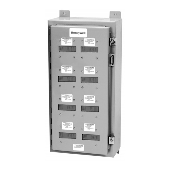
HONEYWELL E-MON® MMU-STYLE METERS 5.0 MMU CABINET INSTALLATION 5.1 MMU Cabinet Description The MMU Cabinet is made from 14 or 16 gauge steel. The cabinet has an ANSI 61 gray exterior finish. It contains a seam that is continuously welded and ground smooth. - Page 9 HONEYWELL E-MON® MMU-STYLE METERS The MMU enclosure is not supplied with knockouts. The installer will make the necessary entrances to the enclosure to supply entry for the voltage and current sensor conductors. The conduit and fittings must be appropriate for the application and installed in a manner to meet national and local electrical codes.
-
Page 10: Mmu Cabinet Wiring
HONEYWELL E-MON® MMU-STYLE METERS 6.0 MMU CABINET WIRING 6.1 General Wiring Instructions Wiring of the individual MMU meters are the same as for a stand-alone meter. See section 7.0. Refer to the Individual Meter Installation Manual for individual meter wiring. - Page 11 HONEYWELL E-MON® MMU-STYLE METERS The proper current sensor wiring to each meter is described in each individual Meter Installation Manual.The MMU style meters are wired the same way, but it is important that proper routing procedures are followed when the current sensor conductors are installed.
- Page 12 HONEYWELL E-MON® MMU-STYLE METERS 6.3 RS485 Communication Wiring The RS485 Communication wiring is installed by connecting the leads to the appropriate terminals on the 3-position RS485 terminal strip mounted on the back panel of the enclosure. The wiring terminals are labeled GND, HIGH, and LOW to correspond to the appropriate connections of the communication cabling.
-
Page 13: Individual Meter Wiring Diagrams And Installation
The menu buttons on the Class 1000 MMU, 2000 MMU, and Green Class MMU Meters are in the same positions as a stand alone Class 1000, 2000 or Green Class Meters. The MMU Menu Buttons are identified in the figure below. If you have any questions, contact Honeywell E-Mon at 800-334-3666. SELECT MENU... -
Page 14: Diagrams And Installation Procedures
Fig. 7. The Menu Buttons on a Class 3200 MMU Meter are Reversed from the Stand Alone Version. 7.3 IDR (Interval Data Recorders) Wiring Diagrams and Installation Procedures Refer to the IDR Installation Manual for detailed wiring diagrams and installation instructions.If you have any questions, contact Honeywell E-Mon at 800-334- 3666. 62-0417—02... -
Page 15: System Wiring Guides
HONEYWELL E-MON® MMU-STYLE METERS Appendix A - System Wiring Guides Connects via USB port on PC KEY* RJ-11 3 FT USB A to USB B cable 4-CONDUCTOR FLAT MODULAR CABLE UP TO 4000 FEET TOTAL DAISY-CHAIN OR STAR CONNECTION (UP TO 8... - Page 16 HONEYWELL E-MON® MMU-STYLE METERS Appendix B - System Wiring Guides Connects via USB port on PC KEY* RJ-11 4-CONDUCTOR FLAT MODULAR CABLE UP TO 4000 FEET TOTAL DAISY-CHAIN OR STAR CONNECTION (UP TO IDR A-B 16 METERS) 8-COND. 6-COND. 6-COND.
- Page 17 HONEYWELL E-MON® MMU-STYLE METERS Appendix C - Modem System Configuration UP TO 8 METERS IDR A IDR-8, USING E-MON D-MON METERS: ® AC ADAPTER UP TO 4000 RS-232 SERIAL PORT FEET TOTAL COM1 THROUGH COM4 MAX. 15' UP TO 52...
-
Page 18: Hardwired System Configuration Diagrams
HONEYWELL E-MON® MMU-STYLE METERS Diagrams Appendix D - Hardwired System Configuration Diagrams IDR-8, USING E-MON D-MON METERS: ® AC ADAPTER UP TO 8 METERS UP TO 4000 FEET TOTAL UP TO CHANNEL 1 52 IDRS RS-232 UP TO 8 METERS... -
Page 19: Hardwired System Configuration Diagrams (Continued)
HONEYWELL E-MON® MMU-STYLE METERS Appendix E - Hardwired System Configuration Diagrams IDR-16, USING E-MON D-MON METERS ® AC ADAPTER UP TO 16 METERS UP TO 4000 FEET TOTAL UP TO 26 IDR-16S CHANNEL 1 RS-232 UP TO 16 METERS SERIAL PORT... -
Page 20: Meter Technical Specifications
Refer to the individual Meter Installation Manual for detailed troubleshooting information. If you have any questions, contact Honeywell E-Mon at 800-334-3666 BEFORE removing the meter. 9.0 METER TECHNICAL SPECIFICATIONS Refer to the individual Meter Installation Manual for detailed technical specifications. -
Page 21: Meter Limited Warranty
2. Honeywell E-Mon must be notified of the defect within ninety (90) days after the defect becomes apparent or known. 3. Buyer’s remedies shall be limited to repair or replacement of the product or component which failed to conform to Honeywell E-Mon’s express warranty... - Page 22 HONEYWELL E-MON® MMU-STYLE METERS 62-0417—02...
- Page 23 HONEYWELL E-MON® MMU-STYLE METERS 62-0417—02...
- Page 24 HONEYWELL E-MON® MMU-STYLE METERS Home and Building Technologies In the U.S.: Honeywell 715 Peachtree Street NE ® U.S. Registered Trademark Atlanta, GA 30308 © 2018 Honeywell International Inc. 62-0417—02 M.S. Rev. 05-18 customer.honeywell.com Printed in United States...