
Related Manuals for Honeywell E-Mon Class 6200


Summary of Contents for Honeywell E-Mon Class 6200
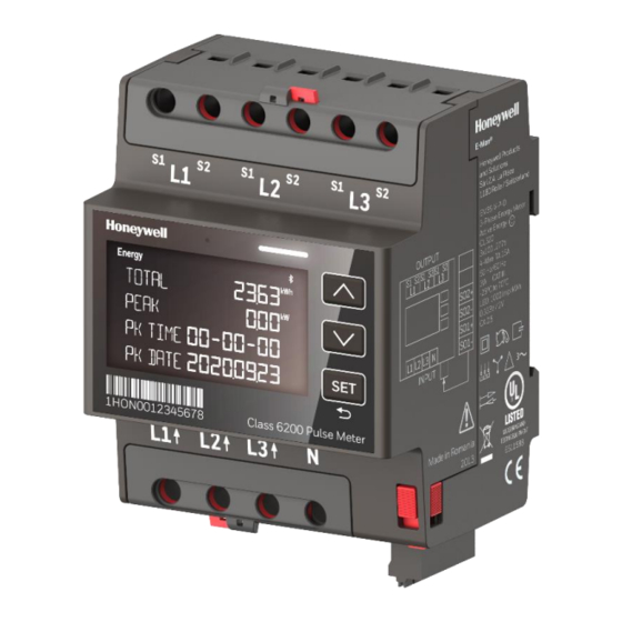
- Page 1 E-Mon® Class 6200 Pulse Meter ENERGY METER WITH SMART MONITORING For more details, visit https://hwll.co/dyut5 © 2021 Honeywell International Inc. 54-000-01-ENG01-0121...
-
Page 2: Disclaimer
Honeywell makes no representations or warranties with respect to this document. In no event shall Honeywell be liable for technical or editorial omissions or precision discrepancies in this document, nor shall it be liable for any damages which may arise (direct or incidental) out of/related to the use of this document. -
Page 3: Table Of Contents
Table of Contents E-Mon® Series - Global User Manual Table of Contents Disclaimer................................2 Table of Contents ..............................3 Safety Information ............................5 1.1. Safety Label Definitions ........................5 1.2. Precautionary and Safety Symbols ....................6 1.3. General Safety Instructions ......................7 1.4. - Page 4 E-Mon® Series Global User Manual Table of Contents 4.2.2. Navigation Diagram ........................ 32 4.3. Default Screens ..........................33 4.3.1. Display Parameters........................33 4.4. Navigating through display screen ..................... 34 4.4.1. Energy Screen Menu ....................... 34 4.4.2. Monitoring Menu ........................39 4.4.3.
-
Page 5: Safety Information
Safety Information E-Mon® Series - Global User Manual 1. Safety Information Kindly follow all the guidelines as suggested in this document. Maintain the standard safety practices of electric installation under consideration along with the safety directives of this document. Strictly comply with all the safety instructions provided in this document before performing any operations with the equipment. -
Page 6: Precautionary And Safety Symbols
E-Mon® Series Global User Manual Safety Information 1.2. Precautionary and Safety Symbols CAUTION: Internal circuit card components are susceptible to electrostatic discharge and humans can easily experience shock. Be careful to not touch the internal circuit unless you are completely discharged. -
Page 7: General Safety Instructions
Safety Information E-Mon® Series - Global User Manual 1.3. General Safety Instructions The following instructions are important for a safe and secure operation and commissioning of the E-Mon® energy meters. Since the meter operation involves high voltage, utmost precautions must be taken during all stages of interacting with the meter. With most of the readings available on the mobile application or monitoring screen, it is advised to avoid touching the meter body except front panel. -
Page 8: Installation Safety Instructions
E-Mon® Series Global User Manual Safety Information 1.4. Installation Safety Instructions The installation involves high voltage as well as various equipment/elements/connection points/exposed zones capable of delivering powerful electrical shocks. Users are advised to follow caution while handling the equipment setup. •... -
Page 9: Operational Safety Instructions
Safety Information E-Mon® Series - Global User Manual 1.5. Operational Safety Instructions The application area of this unit is in industrial, commercial processes and controls of manufacturing lines such as metal, wood, plastic, paper, glass, and textile industries, among others. •... -
Page 10: Fcc Part 15 Notice
E-Mon® Series Global User Manual FCC Part 15 notice FCC Part 15 notice Contains FCC ID: SQGBL654 The enclosed device complies with Part 15 of the FCC Rules. Operation is subject to the following two conditions: (1) This device may not cause harmful interference, and (2) This device must accept any interference received, including interference that may cause undesired operation. -
Page 11: About The Manual
About the manual E-Mon® Series - Global User Manual 2. About the manual The E-Mon® Meters User Manual is a comprehensive guide for setting up and operating E- Mon® Class 6000 energy meter with smart monitoring. This manual offers information on features and functions available in E-Mon® energy meters. It also comprises detailed information on the technical specification of the meters and other hardware. -
Page 12: Overview
E-Mon® Series Global User Manual Overview 3. Overview The E-Mon® meter is poly phase energy meter which offers smart energy metering solution. The device is capable of monitoring electric energy usage of individual loads through the utility meter and storing kW and kVAR data for automatic meter reading. The E-Mon® energy meter measures and records both the import and export energy values. -
Page 13: Meter Characteristics
Overview E-Mon® Series - Global User Manual 3.1. Meter characteristics The E-Mon® meters can be installed on various wiring connection, CS integration, accuracy class etc. You can choose a meter model with adequate characteristics suitable for target application. Measurement Indirect 3 Phase Supply system Delta... - Page 14 E-Mon® Series Global User Manual Overview -13 ºF to 158 ºF (-25°C to 70°C) Ambient Temperature Indoor Indoor/Outdoor Only Mechanical Environment EM Environment 75 % Relative Humidity Resistance to Water (IP Terminals IP20, Front IP 54 Protection) Resistance to Fire and Terminal 1760 °F (960 °C), cover 1202 °F (650 °C), Heat [IEC 60695-2-1]...
-
Page 15: Features
Overview E-Mon® Series - Global User Manual 3.2. Features The E-Mon® energy meter enables users to manage energy cost in an easier way with optimized user experience. Advanced analysis feature of the meter provides high end operational reliability. The Bluetooth application readout function enables users to check electrical values with secure and encrypted data transmission. -
Page 16: Rotating Terminals
E-Mon® Series Global User Manual Overview 3.2.1. Rotating Terminals The device is easy to connect using the rotating terminals as per the available mounting (rail or wall mounting). Kindly refer to the Hardware Installation Guide for details on mounting instruction. The rotating terminals are designed with locks to secure vacant/unused ports and meter connection. -
Page 17: Setup Sealing Button
Overview E-Mon® Series - Global User Manual 3.2.2. Setup Sealing Button Figure 3. Communication Sealing The setup sealing button is dedicated switch for locking in the system configuration settings. The settings are done using the front panel display and navigation buttons and all the system related setup shall be locked prior to the meter operation. - Page 18 E-Mon® Series Global User Manual Overview Figure 4. Protective Enclosure The enclosure body comes with a transparent window for ease of reading the meter display and checking the LED signals. It is designed for viewing the front panel display and protecting the same from withering or damage.
-
Page 19: Bluetooth Communication
Overview E-Mon® Series - Global User Manual Figure 5. Swing - Open panel view WARNING! • Kindly provide a proper ground wiring to the enclosure. Failure to attach the protective earth ground wire securely to the meter steel enclosure terminal leads to shock hazard. -
Page 20: Central Control Via Application
E-Mon® Series Global User Manual Overview 3.2.5. Central control via application The E-Mon® application provides a centralized control of energy meter with the help of a smart phone. Mobile app is available online for download which is simple to install in any smart phone. -
Page 21: Led Signals
Overview E-Mon® Series - Global User Manual to ensure communication security. Refer to section 5.1.2 for configuration using mobile application. LED Signals 3.2.6. The users can check meter status with the help of blinking LED which is mounted on the meter front body. -
Page 22: Current Sensor
E-Mon® Series Global User Manual Overview 3.3. Current Sensor The energy meters come with CS to be installed with the E-Mon® Class 6000 meter. The meter has dedicated terminals for connecting current sensor. The current sensor shall be installed with the meter for Current measurement functions. Figure 7. - Page 23 Overview E-Mon® Series - Global User Manual • The current sensors require UL1015 standard hookup wire leads for connection. • Wires shall be AWG grade with a temperature range of -25 to 105 ºC and voltage range of up to 480 V. CS Model/ Number Current Measurement Mounting...
-
Page 24: Meter Connections
E-Mon® Series Global User Manual Overview 3.4. Meter Connections The E-Mon Energy meters have connection terminals for current sensing using external current sensor. It requires integration of CS of relevant rating to be installed as per specifications. The CS configuration is done using the front panel display by entering primary and secondary values through the Setup menu. -
Page 25: Push-In Terminals
Overview E-Mon® Series - Global User Manual Description Function 8. Communication terminal I/O or Communication (Push-in Connector) 9. In terminal Incoming Connection Terminal 10. Manufacturer id Manufacturer Specific ID 11. LCD Primary User Interface 12. metrology led 1000 imp/kWh 3.4.1. Push-in Terminals The Push in terminals are available to enable easy installation of the device communication. -
Page 26: Firmware And Security
E-Mon® Series Global User Manual Overview navigation buttons. The internal firmware offers secure communication and offers safety from external influence. 3.5.1. Firmware and security The Firmware architecture ensures protection of legally relevant metrological functionality within the micro controller from manipulation. It also allows flexibility to the non- metrologically relevant functionalities and communication options that are essential for the smart metering application. -
Page 27: Communication Security
Overview E-Mon® Series - Global User Manual 3.5.2. Communication Security The device is completely secure for wireless operation with the help of DLMS. The object model can describe the smart metering functionality of E-Mon Class 6000 meters. It allows the meter to translate information with connected device in a secure way. Two layered security has been implemented for a secure communication between the mobile application and the E-meter. -
Page 28: Front Panel Display & Navigation
E-Mon® Series Global User Manual Front Panel Display & Navigation 4. Front Panel Display & Navigation The meter features a front panel LCD display which is a graphical display with 4 lines and 8 digits, and menu buttons allow you to monitor, operate, or modify parameter settings. The device status is shown with signaling LED above the front panel display. -
Page 29: Measurements/ Meter Features Accessible From Front Panel
Front Panel Display & Navigation E-Mon® Series - Global User Manual 4.1. Measurements/ Meter Features accessible from front panel The LCD screen is available in the front panel of meter which offers an interface to display important readings and setting up of various values. Bidirectional Measurement is done using the E-Mon Class 6000 meter where import and export energy readings are available in the front panel and the mobile application. -
Page 30: Data Display Screen Overview
E-Mon® Series Global User Manual Front Panel Display & Navigation 4.2. Data display screen overview The front panel displays 4 lines with 8 digits, it comes with a pair of navigation buttons and one SET button which can be used as a multifunctional switch to browse through functions. The two arrow buttons are used to navigate top-bottom and right-left. -
Page 31: Menu Items Selection
Front Panel Display & Navigation E-Mon® Series - Global User Manual • The selected list option/submenu option is marked with the ‘Select symbol’ as mentioned in table 5. BUTTON NAME FUNCTION Use to navigate up or left in the item list. Down Use to navigate down or right in the item list. -
Page 32: Navigation Diagram
E-Mon® Series Global User Manual Front Panel Display & Navigation 1. Long press the SET button to toggle between menu items or to go back to the main menu. 2. Use Up /Down button to switch between Energy, Monitor and Setup Pages. -
Page 33: Default Screens
Front Panel Display & Navigation E-Mon® Series - Global User Manual The front panel navigation can be done using combination of Up, Down and SET buttons. The screen displays default screen options viz. Total energy, Rated and date/time information. To navigate to the main energy menu, users need to press the SET button for once. -
Page 34: Navigating Through Display Screen
E-Mon® Series Global User Manual Front Panel Display & Navigation NOTE • During initially switching the meter ON, the display will show the Main Menu page. The users can navigate through the screens using the navigation buttons and SET button to setup the meter and browse through various options. •... - Page 35 Front Panel Display & Navigation E-Mon® Series - Global User Manual 1. Total Register – This option displays total flow of energy in the power system. Press the SET button to enter the ‘Total Register’ submenu and use Up/Down navigation button to enter the list items.
- Page 36 E-Mon® Series Global User Manual Front Panel Display & Navigation Access other menu options or go to the default screen using the navigation method ▪ described in Section 4.4. 2. Demand – The front panel display provides demand energy reading (kW) for both import and export energy.
- Page 37 Front Panel Display & Navigation E-Mon® Series - Global User Manual Displays the cumulative () active demand energy (-A) and date, time stamp for ▪ current reading. Long press the SET button to go to the previous sub-menu items within the Energy ▪...
- Page 38 E-Mon® Series Global User Manual Front Panel Display & Navigation 4. Partial – The meter displays partial values for the import and export energy readings. Use the up/down toggle button to highlight the ‘Partial’ option and press SET button to check the partial active energy values.
-
Page 39: Monitoring Menu
Front Panel Display & Navigation E-Mon® Series - Global User Manual iii. Sum (|+AP|+|-AP|) Displays combined total reading of partial active energy for import and export. Scroll down using the navigation button to check for more values. Summation () of combined partial active energy. ▪... - Page 40 E-Mon® Series Global User Manual Front Panel Display & Navigation • Use the SET button in the home screen to highlight options from the main menu items. The underline displays your current menu selection, press Up/Down buttons to toggle selection and use the set button to enter the list items. •...
- Page 41 Front Panel Display & Navigation E-Mon® Series - Global User Manual c. Current –Toggle to the ‘Instant’ option in Monitoring menu and press Down button to check the values. Displays cumulative () instantaneous current (I) and per phase (L1, L2, L3) ▪...
- Page 42 E-Mon® Series Global User Manual Front Panel Display & Navigation f. Instantaneous Reactive Import Power – Displays the instantaneous reactive power imported in the network. Toggle through the instant menu option and press Down arrow button to check the instantaneous reactive import power (-A). Displays combined () instantaneous reactive import power and per phase (L1, L2, L3) ▪...
- Page 43 Front Panel Display & Navigation E-Mon® Series - Global User Manual h. Instantaneous Apparent Power Import - Displays the instantaneous apparent power imported by the network. Toggle through the instant option in the monitoring menu and use the down navigation button to check the values. Displays combined (∑) instantaneous apparent import power.
- Page 44 E-Mon® Series Global User Manual Front Panel Display & Navigation k. Power Factor – Provides the Instantaneous power factor for Import (+PF) and Export (- PF) energy. Toggle through the Instant menu to navigate and check the Instantaneous power factors for Import and Export energy. For import power factor, press the SET button after highlighting +PF sign to check ▪...
- Page 45 Front Panel Display & Navigation E-Mon® Series - Global User Manual a. Line to Neutral voltage – Use the navigation methods as mentioned in Navigation Diagram and select the ‘Monitor’ menu to check the values. Long press SET button to go back to the Menu option.
- Page 46 E-Mon® Series Global User Manual Front Panel Display & Navigation d. Combined Active power (|+A|+|-A|) minimum for the power system. Toggle to the minimum power option using Up/Down arrow buttons in the ‘Monitoring’ menu and press SET to check the values. Provides the cumulative () minimum active power reading (|+A|+|-A|).
- Page 47 Front Panel Display & Navigation E-Mon® Series - Global User Manual Displays the Average line (L1, L2, L3) to neutral (-N) voltage for each phase. ▪ b. Line to line voltage – Use the navigation method to enter ‘Monitor; menu items and use up/down buttons to check values.
- Page 48 E-Mon® Series Global User Manual Front Panel Display & Navigation e. Net Active power (|+A|-|-A|) average for the power system. Toggle to the average active net power option in the ‘Average’ menu by using Up/Down arrow buttons to check the values.
- Page 49 Front Panel Display & Navigation E-Mon® Series - Global User Manual c. Current –Toggle to the current option in maximum menu by pressing Down arrow to check the values. Long press SET to go back to the main screen. Displays cumulative () maximum current (I) and per phase (L1, L2, L3) maximum ▪...
-
Page 50: Setup Menu
E-Mon® Series Global User Manual Front Panel Display & Navigation 4.4.3. Setup Menu The setup menu options allow users to perform system settings for meter operation. Press SET to view the main menu items and use the Up/Down Navigation buttons to highlight Setup. - Page 51 Front Panel Display & Navigation E-Mon® Series - Global User Manual 2. System – This menu provides setup option for the setting system connection type. Navigate to the Setup menu option and select the menu items using the up/down button to highlight list items.
- Page 52 E-Mon® Series Global User Manual Front Panel Display & Navigation Select from the options; 50 Hz and 60 Hz. Toggle through the list items to select the ▪ appropriate nominal frequency and press SET button. 4. Supply – The supply voltage setup is done using this menu option. The nominal supply voltage options are available in the submenu and you can select from appropriate voltage settings.
- Page 53 Front Panel Display & Navigation E-Mon® Series - Global User Manual 5. Wiring Check – This Setup menu option covers alarms to identify missing phases in wiring and power factor error. The wiring check error is identified with yellow blinking LED signal as mentioned in section 3.2.6 Status LED.
- Page 54 E-Mon® Series Global User Manual Front Panel Display & Navigation A list of wiring check alarms with their respective label numbers has been listed in the table below. During the event of an error, the meter front panel will display one of the below mentioned errors with the label number.
- Page 55 Front Panel Display & Navigation E-Mon® Series - Global User Manual iii. Select an option from ‘System’, ‘Phase 1’, ‘Phase 2’, ‘Phase 3’ and press SET to enter an option. Use Up/Down buttons to select an option and press SET to save. a.
- Page 56 E-Mon® Series Global User Manual Front Panel Display & Navigation Secondary Go to setup menu and press SET for menu options. Select ‘CS Ratio Secondary’ option and press the SET button to select secondary current value. iii. Select from given values of current (333 mV and 2 V) on the setup screen. Use Up/Down buttons to select the value as per CS specifications.
- Page 57 Front Panel Display & Navigation E-Mon® Series - Global User Manual 10. Info – Navigate to the Info option in the Setup menu and press SET button to enter the menu options. It displays information on the E-Mon energy meter. Meter –...
-
Page 58: Device Configuration
E-Mon® Series Global User Manual Device configuration 5. Device configuration The E-Mon energy meter is simple to configure and connect to the network. Keep all the electrical parameters in account during configuring the E-Mon energy meter. The CS shall connect with the meter via connecting terminals. Check section 3.3 for current sensors. -
Page 59: Configuration With Front Panel Lcd
Device configuration E-Mon® Series - Global User Manual 5.1. Configuration with Front panel LCD Configure the current sensor using the front panel navigation panel. Connect the wirings using Pozidriv as mentioned in Installation Safety Instructions. Ensure no loose ends or open terminals before starting the user needs to navigate through the menu options in front panel to configure the CS. -
Page 60: Configuration With Mobile Application
E-Mon® Series Global User Manual Device configuration 5.1.2. Setup Sealing Use the setup sealing button as mentioned in section Setup Sealing Button for locking in the parameters which are used in during meter setup. Several the setup parameters are locked with the help of the red setup sealing button. - Page 61 Device configuration E-Mon® Series - Global User Manual 7. The mobile app displays list of discovered meters. 8. Check for the meter serial number as it connects with the phone and tap on the correct number to start pairing. 9. The meter will display a 6-digit pairing code on the front panel. 10.
-
Page 62: Firmware Update
E-Mon® Series Global User Manual Device configuration 5.3. Firmware Update It is important to make sure the availability of latest updates of Firmware during installation. The device functions with updated firmware, however, in case the updates are not downloaded properly during installation, the device will start up with the default version. Firmware updates are downloaded and installed on the go and the machine resets after the complete update is installed. -
Page 63: Pulse Meter Configuration
Pulse Meter Configuration E-Mon® Series - Global User Manual 6. Pulse Meter Configuration The E-Mon® meter has communication terminal at the bottom right of the meter body. This bridge is used to integrate the pulse output. The meter is designed taking utmost consideration of communication safety and data security. -
Page 64: Configuration With Front Panel
E-Mon® Series Global User Manual Pulse Meter Configuration • The terminals have cross section area of 0.2 – 1.5 mm and tolerates a maximum cable length of 3000 ft. It supports solid copper unshielded cable of gauge of 1 mm AWG17. - Page 65 Pulse Meter Configuration E-Mon® Series - Global User Manual Open the communication terminal ports on the bottom right of the meter. Make the necessary connections using the push-in terminals. Press the yellow buttons to open the terminals and join the connectors. iii.
-
Page 66: Pulse And Current Sensor (Cs) Ratio Settings
E-Mon® Series Global User Manual Pulse Meter Configuration 6.3. Pulse and Current Sensor (CS) Ratio Settings The Pulse Ration requires to be in accordance with CS primary values. Check the CS rating and the pulse ratio as mentioned in Section 4.4.3 (6) Setup Menu. Here is a list of all the Pulse Ration settings with their respective CS Primary ratio: CS Primary Pulse Duration... -
Page 67: Bluetooth Communication
Bluetooth Communication E-Mon® Series - Global User Manual 7. Bluetooth Communication Bluetooth communication is used for pairing to commission and read the meter in a more user-friendly mobile App. Use the front panel LCD display for checking the pairing code and verifying the communication security. -
Page 68: Bluetooth Pairing During Wiring Check Alarm
E-Mon® Series Global User Manual Bluetooth Communication iii. The front panel of meter displays the Bluetooth pairing message ‘Bluetooth Pairing Init’ which indicates the meter is discoverable. Launch the mobile App on the phone and check if its updated. Search for devices using the mobile App. Add the meter using the (+) sign on the application. -
Page 69: Fast Commissioning
Fast Commissioning E-Mon® Series - Global User Manual 8. Fast Commissioning The E-Mon energy meter is Bluetooth enabled and easy to commission using the E-Mon mobile application. 8.1. Quick Connect Launch the mobile App on the phone and Tap on ‘Quick Connect’ option at the bottom pane. - Page 70 E-Mon® Series Global User Manual Fast Commissioning The commissioning screen displays the progress in meter commissioning. The next screen displays the list of energy meters which have been commissioned. vii. Use select the meter serial number and tap on to view the project overview. Page | 70 54-000-01-ENG01-0121...
-
Page 71: Wiring Check
Fast Commissioning E-Mon® Series - Global User Manual 8.4. Wiring Check 8.4.1. E-Mon Energy Meter Use the energy meter front panel display to check and acknowledge the wiring check alarm and PF error message. During a missing phase voltage, the energy meter LED blinks with red color to notify the user about a missing phase voltage and power factor error. - Page 72 E-Mon® Series Global User Manual Fast Commissioning Page | 72 54-000-01-ENG01-0121...
-
Page 73: Security Definitions
Security Definitions E-Mon® Series - Global User Manual 9. Security Definitions The security section enlists certain factors to protect the integrity of the E-Meter during installation and operation. The users at all time shall be aware about data security and integrity of the meter parts such as firmware, hardware and front panel display. - Page 74 E-Mon® Series Global User Manual Security Definitions The E-Mon meter has locks for sealing the communication and connection terminals which requires physical access to the meter. All the terminal sealings must be intact and the terminal locks on. • The red buttons are designed to lock the terminals and connections, avoid unlocking them at any time except if necessary.
- Page 75 Security Definitions E-Mon® Series - Global User Manual 9.2.3. Meter Enclosure The meter comes with a metallic enclosure to safeguard various metering components. The enclosures are designed for robustness and secure meter operation. They are also designed to withstand several adverse operational conditions. You can choose a meter enclosure as per operational necessity.
-
Page 76: Firmware & Communication
E-Mon® Series Global User Manual Security Definitions NOTE • All devices must be enclosed in a cabinet and closed. • Restricted access to E-Meter buttons. • Attach the secure earth grounding wire to the grounding terminal of the enclosure for safety. •... - Page 77 Security Definitions E-Mon® Series - Global User Manual • Ensure that the mobile application is closed after Bluetooth commissioning. Leaving an open connection may lead to security compromise. NOTE • Close the application after successfully commissioning the meter and setting up the parameters.
-
Page 78: Troubleshooting
E-Mon® Series Global User Manual Troubleshooting 10. Troubleshooting The meters are practically maintenance free as it doesn’t contain any user-serviceable or replaceable parts. Therefore, the meter does not require any special maintenance schedule. However, in case of any malfunctioning or suspicion of glitches, kindly refer to the following troubleshooting methods. - Page 79 Troubleshooting E-Mon® Series - Global User Manual Problem Statement Action 12. Keep adequate proximity from the setup to avoid accidents. Switch the meter off and on again to check for the front Front Panel Display Frozen/ panel display. Unable to edit values Note –...
-
Page 80: Frequently Asked Questions
• If the problem cannot be fixed with the steps provided in this section, then contact local Honeywell E-mon representative or an Authorized Service Center. • Do not touch the meter body for troubleshooting as it may cause electrical shock. - Page 81 (SKU: EM3S-P-V-M, including the DIN meter and the mounting kit). How is the accuracy certified on Class6200? E-Mon Class 6200 is a revenue grade meter with ANSI C12.20 certificate (Class 0.5), like our legacy E-Mon bestsellers. Do I need to set the Pulse parameters during commissioning? ...
-
Page 82: Appendix A - Nomenclature
E-Mon® Series Global User Manual Appendix A – Nomenclature Appendix A – Nomenclature Page | 82 54-000-01-ENG01-0121... -
Page 83: Appendix B - List Of Abbreviations
Appendix B – List of Abbreviations E-Mon® Series - Global User Manual Appendix B – List of Abbreviations Acronym Full Form Current Ø Power Factor NEMA National Electrical Manufacturers Association Input Output Volts Alternating Current Current Sensor Light emitting diode Bluetooth Low Energy Bluetooth BLMS... - Page 84 E-Mon® Series - Global User Manual By using this Honeywell literature, you agree that Honeywell will have no liability for any damages arising out of your use or modification to, the literature. You will defend and indemnify Honeywell, its affiliates and subsidiaries, from and against any liability, cost, or damages, including attorneys' fees, arising out of, or resulting from, any modification to the literature by you.