
Related Manuals for Honeywell MZ-PCSV74


Summary of Contents for Honeywell MZ-PCSV74
- Page 1 Dell T130 Honeywell Server Planning, Installation and Service Guide HWDOC-X450-en-D November 2019...
- Page 2 Honeywell International Sàrl. While this information is presented in good faith and believed to be accurate, Honeywell disclaims the implied warranties of merchantability and fitness for a purpose and makes no express warranties except as may be stated in its written agreement with and for its customer.
-
Page 3: Table Of Contents
Chapter 1 - About this Document Chapter 2 - Planning 2.1 Overview 2.1.1 Software requirement 2.1.2 BIOS configuration 2.2 Description 2.2.1 Honeywell server model number 2.2.2 Electronics configuration 2.2.3 Electronics module 2.2.4 Standard features of Dell T130 2.2.5 Slots configuration 2.2.6 Optional features 2.2.7 Power cords... - Page 4 3.1.1 Before you begin 3.2 Power and grounding requirements 3.3 Cabinet spacing requirements 3.4 Installing Dell T130 server and connecting cables 3.4.1 Honeywell server back panel connections 3.4.2 Connecting the cables 3.5 Starting the server 3.5.1 Turning on the power Chapter 4 - Operation 4.1 Server overview...
-
Page 5: Chapter 1 - About This Document
Honeywell factory or has manuals dedicated to its installation and service. This server is not a standard Dell model and you cannot order it independently from Dell. - Page 6 Chapter 1 - About this Document Publication Content Type Experion LCN Hardware UEA installation Upgrade Kit Instructions (51195195-415) Experion LCN Quick Start General hardware/software/migration information Guide (EPDOC-X480-en- 510A) Experion Software Installation Experion software installation (various methods) User's Guide (EPDOC-X136- en-510A) Experion LCN Overview and Bridge hardware installation, software configuration, Implementation Guide...
-
Page 7: Revision History
Chapter 1 - About this Document Publication Content Type system menu functions, console/station peripheral devices Integrated Experion-TPS Supplementary installation and configuration tasks for User's Guide (EPDOC-XX66- Experion TPS Nodes en-510A) Experion PKS R510.1 Planning information for migration of Experion system Migration Planning Guide from legacy R4xx system software to Experion R510.1 software. -
Page 8: Chapter 2 - Planning
Light industrial regulatory compliance Overview Platforms sold by Honeywell are engineered for the process control mission of Experion and TPS systems to provide consistent and robust performance. Through an extensive qualification process, Honeywell defines specific peripheral devices, slot locations, and BIOS settings for best performance and reliability, sometimes even adding cooling fans for longer service. -
Page 9: Bios Configuration
Windows Server 2016 COA COAS16 2.2.2 Electronics configuration The Dell T130-based server is approved for installation in 800 and 1000 mm deep Honeywell LCN cabinets using either a "fixed" mounting kit, model number TP-SPCMF1, or a "slide" mounting kit, model number TP-SPCMS1. 2.2.3... -
Page 10: Standard Features Of Dell T130
Chapter 2 - Planning platforms. Typical operating power requirements Description DC power AC voltage AC RMS current AC power Electronic assembly 120 (90-132) Vrms 0.7A 240 (180-260) 0.3A Vrms Maximum operating power requirements Description DC power AC voltage AC RMS current AC power Electronic assembly 120 (90-132) Vrms 0.9A... -
Page 11: Slots Configuration
Platform information Honeywell documentation Dell documentation 2.3.1 Honeywell documentation The following table lists the Honeywell publications that may be useful when installing or operating your system. Publication Contains information about Fault Tolerant Ethernet Installation and Installing and using FTE on a TPS or Service Guide Experion PKS node. - Page 12 Chapter 2 - Planning system. Is available Publication Contains information about with Readme files Last-minute updates about technical changes The drivers and to the server or advanced technical reference utilities CD material for experienced users or technicians. Dell System Warranty and safety Packaged with Information Guide the computer...
-
Page 13: Experion Nodes Slot Requirement
Chapter 2 - Planning Experion nodes slot requirement 2.4.1 Default configurations for FTE Broadcom on-board NICs are enabled without PXE. If you are using FTE slot only, then use on-board NICs. 2.4.2 FTE supervisory (Default) FTE must be configured on on-board NIC. Slot number Description Option... -
Page 14: System Specifications
Chapter 2 - Planning UDIMM 2133 MHz or faster. DIMM socket Memory size Channel 8 GB UDIMM 8 GB UDIMM System specifications 2.6.1 Microprocessor Microprocessor Tab 100 / Tab 200: Skylake Intel Xeon E3-1220V5 ,3.0 GHz, 8M cache, 8GT/s. Intel Smart 8 MB Cache Chipset... -
Page 15: Raid Controller
Chapter 2 - Planning 2.6.2 Memory Architecture Tab 100: 8 GB (2 x 4 GB UDIMM DDR4, 2133 MHz) or faster Tab 200: 16GB (2x8 GB UDIMM DDR4, 2133MHz) or faster DIMM sockets Tab 100: 4 UDIMM DDR4 Tab 200: 8GB UDIMM 2133MHz or faster DIMM capacities 4 GB UDIMM, 2133 MHz Minimum RAM... - Page 16 Chapter 2 - Planning 2.6.8 Environmental Operating temperature +10 °C to +35 °C (50 °F to 95 °F) with a maximum temperature gradation of 10° per hour. Note: For Altitudes above 2950 feet , the maximum operating temperature is derated 1 °F/550 ft. All temperature ratings shown are for sea level.
-
Page 17: Drive Bays
Chapter 2 - Planning billion CI2 Gas concentration CI2 Gas concentration < 50 mm3/m3 parts per billion NOX Gas concentration NOX Gas concentration < 1 mm3/m3 parts per billion HF Gas concentration HF Gas concentration < 500 mm3/m3 parts per billion NH3 Gas concentration NH3 Gas concentration <... -
Page 18: External Ports
Chapter 2 - Planning 2.6.12 Maximum Shock Operating Six consecutively executed shock pulses in the positive and negative x, y, and z axes of 40 G for up to 2.3 ms. Storage Six consecutively executed shock pulses in the positive and negative x, y, and z axes (one pulse on each side of the system) of 71 G for up to 2 ms. -
Page 19: Hard Disk Drive Specifications
2.6.19 Removable media specifications The Honeywell-based Dell T130 server has one SATA DVD- RW drive. The SATA DVD-RW drive is connected to the SATA connector on the motherboard. DC 5 volt power, 6.5 Watts is the operating power requirement for DVD RW drive. -
Page 20: Mouse And Keyboard
2.6.22 Monitor The Honeywell-based Dell T130 server supports industrial standard video format (typically 1024X768 at a refresh rate of 75Hz). You must use a multisync monitor along with the Dell T130 server platform operating system. The server can be configured only with a single screen option. In this configuration, the monitor is connected to the AGP video controller output connector. -
Page 21: Safety Compliance
The compliance specifications in this section apply to installations other than cabinets. ATTENTION Honeywell does not claim Safety Compliance or Electromagnetic Compatibility (EMC) Compliance for system equipment configurations that have not been described in this guide as standard system configurations. Any equipment configuration other than that described in this publication decertifies the Safety and EMC compliance of this product. -
Page 22: Safety Compliance
Chapter 2 - Planning Regulatory) for European community. Element Description Emissions IEC 61326, 1997 (Basic Requirements, CISPR 11, Class A) Immunity IEC 61326, 1997 (Basic Requirements) ATTENTION The following formula is a proximity guideline, for use of Portable Transceivers (walkie-talkies) in the frequency range of 80MHz to 1GHz. -
Page 23: Chapter 3 - Installation
CHAPTER NSTALLATION This section describes the procedures for installing the platform and cabling the server in a 1-meter deep Honeywell cabinet. Tasks for installing the server Power and grounding requirements Starting the server Tasks for installing the server The following table lists the major platform installation tasks. -
Page 24: Cabinet Spacing Requirements
Due to thermal constraints, only one Dell PowerEdge T130 server can be mounted on a new build 1- meter deep Honeywell MP-C1MCB1 cabinet. The server must be mounted on rack space interval 11U through 15U counting from the bottom of the cabinet and moving up. Install a 1U air duct baffle and blank front panel in the rails directly above the server. -
Page 25: Installing Dell T130 Server And Connecting Cables
(mm) deep LCN cabinets, model number MP-C8LCB1-Tab and MP-C1MCB1-Tab respectively. This procedure assumes that a new 800 or 1000 mm deep cabinet was shipped from the Honeywell factory with either the “fixed rail” mounting kit, model number TP-SPCMF1, or the “slide tray” mounting kit, model number TP-SPCMS1, pre-installed. -
Page 26: Connecting The Cables
Failure to do so may result in tripping the circuit breakers. 2. Connect the Honeywell AC power cords. 3. Perform any one of the following, as necessary. If you are not using Fault Tolerant Ethernet (FTE), connect the Ethernet cable to the on-board RJ-45 connector. -
Page 27: Starting The Server
Chapter 3 - Installation 5. If necessary, refer to the section Install air duct baffles and blank panel front covers in cabinet. ATTENTION Any unused rack mount space must have an air duct baffle and blank front panel installed. 6. To complete the installation, turn on the server. Starting the server Turning on the power 3.5.1... -
Page 28: Chapter 4 - Operation
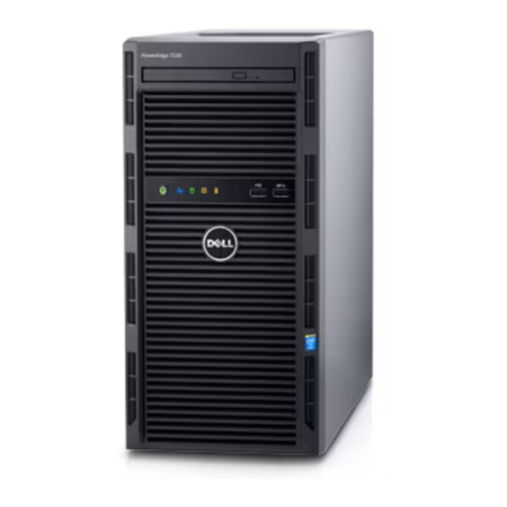
4.1.1 Front view of Dell T130 The following image illustrates the front view of the Dell T130 server for MZ-PCSV74. This server is provided with 3.5 inch Hot-swappable hard-drive chassis. Figure 4.1 Front panel with 3.5 inch Hot-swappable hard-drive chassis The following are the explanation for the items in the images. -
Page 29: Rear View Of Dell T130
Chapter 4 - Operation 1. Diagnostic INdicators 2. Power-on Indicator, Power Button 3. Optical Drive (Optional) 4. USB Connector 5. USB Connector 4.1.2 Rear view of Dell T130 The following image illustrates the rear view of the Dell T130 server. The following are the explanation for the items in the image. -
Page 30: Network Connections
MAU connection ControlNet Network 4.2.1 Ethernet network ETHERNET 10/100/1000 Base T connection is the standard connection used on the Honeywell- configured platform. An on-board dual NIC must be used for FTE configuration. 4.2.2 MAU connection Connect the MAU to both Cable A and Cable B coax T-connector as illustrated in the following Figure. -
Page 31: Configuring Controlnet Interface Card
3. Go to the Product Support section. 4. Search for Magma PE3R instructions. Installing ControlNet card inside Magma chassis 4.3.1 Installing ControlNet card inside Magma chassis Refer to the Magma PE3R Installation Instruction available at the following Honeywell Process - 31 -... - Page 32 Chapter 4 - Operation Solutions support website before installing the third party hardware cards inside Magma chassis. https://www.honeywellprocess.com/library/support/Documents/Experion/Magma_Installation_ Instructions_HWDOC-X279-en.pdf. - 32 -...
-
Page 33: Chapter 5 - Servicing
CHAPTER ERVICING Removing the Side Cover Servicing the hard disk drives and power supply Troubleshooting Removing the Side Cover To remove or installs the components on the motherboard; you must first remove the side cover. 5.1.1 To remove the side cover 1. -
Page 34: Servicing The Hard Disk Drives And Power Supply
Servicing the hard disk drives and power supply The server from Honeywell is configured with five 146 GB or 300 GB SAS hard drives for RAID-5 configuration and the fifth hard drive is a hot spare. The configuration also contains redundant power supplies. -
Page 35: Servicing Honeywell Options
Slot requirements for General Ethernet and FTE node setup 5.3.1 Slot requirements for General Ethernet and FTE node setup The following table identifies the specific slots for each of the Honeywell options for general Ethernet and FTE node configurations. PCIe x 8... -
Page 36: Adding Additional Memory
Chapter 5 - Servicing Adding additional memory The standard memory capacity is 4 GB. The system memory can be increased to 8 GB, MZ-PCEM15. Memory devices must be from the same memory supplier. For further information about the memory configurations, refer to the section Memory configuration for Dell T130. -
Page 37: Installing Pcic Card In Dell T130 Server Using Magma
Chapter 5 - Servicing 4. Insert the memory module. 5. Align the edge of the memory module connector with the alignment key on the memory module socket, and insert the memory module into the socket. ATTENTION The memory module socket has an alignment key that allows you to install the memory module in the socket only in one way. - Page 38 Chapter 5 - Servicing 5.5.1 To insert the Magma PCIe card 1. Shut down the computer. 2. Remove the power cords from the rear end of the server and wait for 20 seconds. 3. Remove the front bezel. Refer to the section Removing the front bezel.
- Page 39 Chapter 5 - Servicing 8. While wearing a grounded ESD wrist strap, grasp the Magma PCIe host card at the corners and gently insert it in slot 1. 9. Align the Magma PCIe host card edge with the card edge guide. 10.
-
Page 40: Verifying Correct Bios Settings
Chapter 5 - Servicing Verifying correct BIOS settings All Honeywell systems must have the Honeywell recommended BIOS version. Honeywell configures specific BIOS settings in the factory for each of the server platform configurations, and these settings must not be altered. The following table provides the default BIOS settings for the server. - Page 41 Chapter 5 - Servicing Memory information System memory size 8 GB System memory type ECC DDR4 System memory speed 2133 MHz System memory voltage 1.20 V Video memory 16 MB System memory testing Disabled Memory operating mode Optimizer Mode CPU information Virtualization technology Enabled Adjacent cache prefetcher...
- Page 42 Chapter 5 - Servicing Processor 1 Family – Model – Stepping 06-5E-3 Brand Intel® Xeon® CPU E3-1220V5 @ 3.00 GHz] Level 2 Cache 4 X 256 KB Level 3 Cache 8 MB Number of cores Mircocode 0x74 SATA settings Embedded SATA AHCI mode Security Freeze lock Enabled...
- Page 43 Chapter 5 - Servicing Boot settings Boot Mode BIOS Boot Sequence Retry Enabled Hard disk Failover Disabled Boot sequence 1. Embedded SATA Port Optical Drive E: [DVD drive model number] 2. Hard Drive C: 3. Embedded NIC1 Port 1 Partition1 : BRCM MBA Slot 0200 v17.0.1 or higher Boot option Enable / Disable 1.
- Page 44 Chapter 5 - Servicing Slot Disablement Global Slot Boot driver disable Disabled Slot 1 Enabled Slot 2 Enabled Slot 3 Enabled Slot 4 Enabled Serial communication Serial communication On without Console Redirection Serial Port Address Serial Device 1 = COM1 Serial Device 2 = COM2 External Serial Connector Serial Device 1...
- Page 45 Chapter 5 - Servicing System profile settings System profile Performance CPU Power Management Maximum Performance Memory Frequency Maximum Performance Tubo boost Enabled Disabled C states Disabled Memory refresh rate Uncore Frequency Maximum Energy efficient policy Performance Number of Turbo boost enabled cores for processor 1 Monitor/Mwait Enabled - 45 -...
- Page 46 Chapter 5 - Servicing System security Intel AES-NI Enabled System Password Not Enabled Setup Password Not Enabled Password Status Unlocked TPM Security TPM information NO TPM present TPM Status Unknown TPM Command None Intel TXT Power Button Enabled NMI Button Disable AC Power Recovery AC power recover delay...
-
Page 47: Bios Settings For Tab 51156307-200
Chapter 5 - Servicing Miscellaneous settings System Time HH:MM:SS System date MM:DD:YYYY Asset Tag Keyboard Num Lock F1/F2 Prompt on Error Enabled Load legacy Video Option Rom Disabled 5.6.3 BIOS settings for Tab 51156307-200 System information Product name Dell PowerEdge T130 server BIOS Version 1.4.5 or higher System management Engine version... - Page 48 Chapter 5 - Servicing Memory information System memory size 16 GB System memory type ECC DDR4 System memory speed 2133 MHz System memory voltage 1.20 V Video memory 16 MB System memory testing Disabled Memory operating mode Optimizer Mode CPU information Virtualization technology Enabled Adjacent cache prefetcher...
- Page 49 Chapter 5 - Servicing Processor 1 Family – Model – Stepping 06-5E-3 Brand Intel® Xeon® CPU E3-1220V5 @ 3.00 GHz] Level 2 Cache 4 X 256 KB Level 3 Cache 8 MB Number of cores Mircocode 0 x 9c or higher SATA settings Embedded SATA AHCI mode...
- Page 50 Chapter 5 - Servicing Boot settings Boot Mode BIOS Boot Sequence Retry Enabled Hard disk Failover Disabled Boot sequence 1. Embedded SATA Port Optical Drive E: [DVD drive model number] 2. Hard Drive C: 3. Embedded NIC1 Port 1 Partition1 : BRCM MBA Slot 0200 v17.0.1 or higher Boot option Enable / Disable 1.
- Page 51 Chapter 5 - Servicing Slot Disablement Global Slot Boot driver disable Disabled Slot 1 Enabled Slot 2 Enabled Slot 3 Enabled Slot 4 Enabled Serial communication Serial communication On without Console Redirection Serial Port Address Serial Device 1 = COM1 Serial Device 2 = COM2 External Serial Connector Serial Device 1...
- Page 52 Chapter 5 - Servicing System profile settings System profile Performance CPU Power Management Maximum Performance Memory Frequency Maximum Performance Tubo boost Enabled Disabled C states Disabled Memory refresh rate Uncore Frequency Maximum Energy efficient policy Performance Number of Turbo boost enabled cores for processor 1 Monitor/Mwait Enabled - 52 -...
- Page 53 Chapter 5 - Servicing System security Intel AES-NI Enabled System Password Not Enabled Setup Password Not Enabled Password Status Unlocked TPM Security TPM information NO TPM present TPM Status Unknown TPM Command None Intel TXT Power Button Enabled NMI Button Disable AC Power Recovery AC power recover delay...
-
Page 54: Exiting The Bios
To exit the BIOS settings 1. In System Setup choose File > Save changes and exit. A confirmation message appears. 2. Click Yes. Spare parts Dell part Honeywell Item Description number part number Expansion 4 GB ECC DDR4, UDIMM 2133 Mhz or... -
Page 55: Documentation Feedback
Documentation feedback You can find the most up-to-date documents on the Honeywell Process Solutions support website at: http://www.honeywellprocess.com/support If you have comments about Honeywell Process Solutions documentation, send your feedback to: hpsdocs@honeywell.com... - Page 56 For support, contact your local Honeywell Process Solutions Customer Contact Center (CCC). To find your local CCC visit the website, https://www.honeywellprocess.com/en-US/contact-us/customer- support-contacts/Pages/default.aspx. Training classes Honeywell holds technical training classes that are taught by process control systems experts. For more information about these classes, contact your Honeywell representative, or see http://www.automationcollege.com. - 56 -...