
Related Manuals for GE PANDA


Summary of Contents for GE PANDA
- Page 1 ™ ™ Panda and Giraffe Warmers Service Manual M1128921 Revision J Class A © 2007-2017 General Electric Company All rights reserved.
- Page 2 General Electric Company reserves the right to make changes in specifications and features shown herein, or discontinue the product described at any time without notice or obligation. Contact your GE Representative for the most current information. Trademarks GE, the GE Monogram, Giraffe, and Panda are trademarks of General Electric Company.
- Page 3 Implemented updates supporting LED display design change. Added sample UDI symbol and description, and scale checkout March 2016 and calibration procedures. Updated part numbers and names of Panda and Giraffe Warmers. Added printing specification to Service Manual bill of material October 2014 (BOM).
- Page 4 RH-2 Service Manual...
-
Page 5: Table Of Contents
1.3.8 Display............................... 1-16 1.3.9 Touch Panel ............................1-16 1.3.10 Elevating Base (Bedded Models Only)..................1-17 1.3.11 Observation Lights..........................1-18 1.3.12 Procedure Light (Optional on Panda Warmer) ..............1-18 1.3.13 Heat Control ............................1-19 1.3.14 Scale (Bedded Models Only) ......................1-23 TOC-1... - Page 6 1.3.15 SpO2 ................................ 1-23 1.3.16 Alarms..............................1-24 1.3.17 Equipment Grounding........................1-25 1.3.18 AC/DC Power Distribution ......................1-26 1.4 RS-232 Serial Data............................1-27 1.4.1 RS-232 Connector ..........................1-27 1.4.2 Data Stream ............................1-27 1.4.3 Nurse Call ..............................1-28 Chapter 2: Installation, Maintenance, and Checkout ..........2-1 2.1 Warmer Maintenance Schedule .........................2-1 2.1.1 Operator Maintenance.........................2-1 2.1.2 Service Maintenance..........................2-1...
- Page 7 4.2.2 PC Command Line Interface Main Menu .................. 4-14 4.2.3 PC Command Line Interface Sub-Menus.................. 4-15 4.2.4 Engineering Log Dump........................4-18 4.3 Troubleshooting Information........................4-21 4.4 Troubleshooting Tables..........................4-22 4.4.1 Lighting – Procedure Light....................... 4-22 4.4.2 Lighting – Observation Lights ......................4-24 4.4.3 Display –...
- Page 8 6.10.5 Panda Scale Parts..........................6-26 6.10.6 Power Cords ............................6-26 6.11 Labels................................. 6-27 6.11.1 Labels on the Back of Giraffe Warmers or Panda iRes Warmers....... 6-27 6.11.2 Heater Grille Accessory Warning Label Set (Bedded Models) ........6-28 6.11.3 Labels on Probe Panel Housing....................6-29...
- Page 9 6.11.4 Control Panel Labels (Not Shown, See Figure 1-4)............. 6-29 6.11.5 Labels on Freestanding Model....................6-30 6.11.6 Labels on Wall Mount Model......................6-32 6.12 Test Points................................ 6-36 6.12.1 Control Board............................6-36 6.12.2 Power Board............................6-37 6.13 Wiring Diagrams............................6-38 Appendix A: Specifications..................A-1 A.1 Power Requirements and Accessory Outlets ..................A-1 A.2 Operating Environment...........................A-1 A.3 User Control Settings ............................A-1...
- Page 10 D.1.4 Diagnostics Using Serial Port......................D-3 D.1.5 File Capture .............................. D-4 Appendix E: Installing Wall Mount Units ..............E-1 E.1 Pre-Installation Preparation..........................E-2 E.2 Wall Mount Bracket Installation ........................E-3 E.3 Bumper Installation (for Installations with Bassinets)...............E-6 E.4 Heater Head Installation and Heater Alignment.................E-7 E.5 Mattress Height Label Installation (for Installations with Bassinets) ........
-
Page 11: About This Manual
About this Manual Scope and Intended Users This service manual describes how to maintain, repair, and service the Panda and Giraffe Warmers that are used in hospital delivery rooms, hospital newborn nurseries and neonatal intensive care units (NICU). The intended users for this manual are biomedical engineering service providers of the hospital and GE Service personnel. - Page 12 About this Manual User Responsibility Service Manual...
-
Page 13: Important Safety Information
The information contained in this service manual pertains only to those models of products which are marketed by GE Healthcare as of the effective date of this manual or the latest revision thereof. This service manual was prepared for exclusive use by GE Healthcare service personnel in light of their training and experience as well as the availability to them of parts, proper tools, and test equipment. -
Page 14: Warnings, Cautions, And Notes
Important Safety Information Warnings, Cautions, and Notes Warnings, Cautions, and Notes Warning: Do not use the warmer in the presence of flammable anesthetics; an explosion hazard exists under these conditions. Warning: Thoroughly air dry the warmer after cleaning it with flammable agents. Small amounts of flammable agents, such as ether, alcohol or similar cleaning solvents left in the incubator can cause a fire. -
Page 15: Service Language Disclaimer
No repairs should ever be undertaken or attempted by anyone not having such qualifications. Genuine replacement parts manufactured or sold by GE Healthcare must be used for all repairs. Read completely through each step in every procedure before starting the procedure;... - Page 16 Important Safety Information Warnings, Cautions, and Notes 警告 本维修手册仅提供英文版本。 • 如果客户的维修服务人员需要非英文版本,则客户需自行提供翻译服务。 (ZH-CN) • 未详细阅读和完全理解本维修手册之前,不得进行维修。 • 忽略本警告可能对维修服务人员、操作人员或患者造成电击、机械伤害或其他形 式的伤害。 警告 本服務手冊僅提供英文版本。 • (ZH-HK) 倘若客戶的服務供應商需要英文以外之服務手冊,客戶有責任提供翻譯服務。 • 除非已參閱本服務手冊及明白其內容,否則切勿嘗試維修設備。 • 不遵從本警告或會令服務供應商、網絡供應商或病人受到觸電、機械性或其他的 危險。 警告 本維修手冊僅有英文版。 • (ZH-TW) 若客戶的維修廠商需要英文版以外的語言,應由客戶自行提供翻譯服務。 • 請勿試圖維修本設備,除非 您已查閱並瞭解本維修手冊。 • 若未留意本警告,可能導致維修廠商、操作員或病患因觸電、機械或其他危險而 受傷。 UPOZORENJE Ovaj servisni priručnik dostupan je na engleskom jeziku. •...
- Page 17 Versuchen Sie nicht diese Anlage zu warten, ohne diese Serviceanleitung gelesen und verstanden zu haben. • Wird diese Warnung nicht beachtet, so kann es zu Verletzungen des Kundendiensttechnikers, des Bedieners oder des Patienten durch Stromschläge, mechanische oder sonstige Gefahren kommen. Service Manual...
- Page 18 άλλους κινδύνους. FIGYELMEZTETÉS Ezen karbantartási kézikönyv kizárólag angol nyelven érhető el. • Ha a vevő szolgáltatója angoltól eltérő nyelvre tart igényt, akkor a vevő felelőssége a (HU) fordítás elkészíttetése. • Ne próbálja elkezdeni használni a berendezést, amíg a karbantartási kézikönyvben leírtakat nem értelmezték.
- Page 19 Important Safety Information Warnings, Cautions, and Notes 警告 このサービスマニュアルには英語版しかありません。 サービスを担当される業者が英語以外の言語を要求される場合、翻訳作業はそ • (JA) の業者の責任で行うものとさせていただきます。 このサービスマニュアルを熟読し理解せずに、装置のサービスを行わないでく • ださい。 この警告に従わない場合、サービスを担当される方、操作員あるいは患者 さん • が、感電や機械的又はその他の危険により負傷する可能性があります。 경고 본 서비스 매뉴얼은 영어로만 이용하실 수 있습니다 . • (KO) 고객의 서비스 제공자가 영어 이외의 언어를 요구할 경우 , 번역 서비스를 제공하 는...
- Page 20 Important Safety Information Warnings, Cautions, and Notes OSTRZEŻENIE Niniejszy podręcznik serwisowy dostępny jest jedynie w języku angielskim. • Jeśli serwisant klienta wymaga języka innego niż angielski, zapewnienie usługi (PL) tłumaczenia jest obowiązkiem klienta. • Nie próbować serwisować urządzenia bez zapoznania się z niniejszym podręcznikiem serwisowym i zrozumienia go.
- Page 21 Important Safety Information Warnings, Cautions, and Notes UPOZORENJE Ovo servisno uputstvo je dostupno samo na engleskom jeziku. • Ako klijentov serviser zahteva neki drugi jezik, klijent je dužan da obezbedi (SR) prevodilačke usluge. • Ne pokušavajte da opravite uređaj ako niste pročitali i razumeli ovo servisno uputstvo.
- Page 22 Important Safety Information Warnings, Cautions, and Notes DİKKAT Bu servis kılavuzunun sadece ingilizcesi mevcuttur. • Eğer müşteri teknisyeni bu kılavuzu ingilizce dışında bir başka lisandan talep ederse, (TR) bunu tercüme ettirmek müşteriye düşer. • Servis kılavuzunu okuyup anlamadan ekipmanlara müdahale etmeyiniz. •...
-
Page 23: Symbols
Important Safety Information Symbols Symbols This section identifies the symbols that are displayed on the Panda and Giraffe Warmers: Symbol Description Type B Equipment Functional Earth Terminal Protection Earth Terminal Alternating Current Alarm Silence European Union Representative Consult accompanying documents. -
Page 24: Regulatory
Identifier (UDI). The UDI label will be located on or adjacent to the serial number label on the device. Example of UDI label format: Regulatory GE Healthcare has declared that this product conforms with the European Council Directive 93/42/EEC Medical Device Directive when it is used in accordance with the instructions provided in the Operation and Maintenance Manual. -
Page 25: Chapter 1: Functional Description
The Panda and Giraffe Warmers are each offered in a bedded model: the Panda iRes Warmer and the Giraffe Warmer. The Panda Warmer also offers two non-bedded models: Freestanding and Wall Mount. The model type is indicated on the label and on the device’s splash screen. - Page 26 Giraffe Warmer, but the procedure light is optional. All Giraffe and Panda units feature the same heater head to house the radiant heater. Due to the small size of the heater reflector and its compound elliptical shape, designed specifically for this product, the heater head is very compact compared with other warmers currently on the market.
- Page 27 An additional feature, unique among warmers is the Hands Free Alarm Silence. This is a standard feature on all Giraffe and Panda Warmers. Alarms may be silenced just as they would with the alarm silence button, but without touching the unit. The proximity sensor for the Hands Free Alarm Silence is located in the alarm light panel.
-
Page 28: Mechanical Controls And Cable Connections
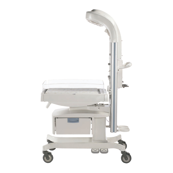
Procedure light “On/Off” switch Color display screen Resuscitation system (optional) Bedded and Freestanding Bed, with optional scale (bed styles are different on Giraffe and Panda) Bedded Front bedside panel (bed styles are different on Giraffe and Panda) Bedded Bed tilt control lever... - Page 29 FIGURE 1-2. Panda Warmer, Side View Feature Description Model Number Recessed radiant heater Side bedside panel (bed styles are different on Giraffe and Panda) Bedded Front handle Bedded Pass through drawer, (single-drawer or double-drawer) (optional) Bedded Two bed height adjustment pedals, up and down (optional)
- Page 30 Chapter 1: Functional Description Introduction FIGURE 1-3. Panda Warmer, Rear View Feature Description Model Number RS-232 connector Two accessory power outlets system (optional) Removable rear bedside panel Bedded Power cord inlet Mains power switch Suction Bottle holder (only on units with resuscitation system)
-
Page 31: Controls And Displays
Chapter 1: Functional Description Introduction 1.1.2 Controls and Displays Feature Description Number Power stand-by switch - On the left below the display turns the power to the warmer on and off. logo (optional) - Indicates which SpO system is installed: Masimo SET (1 or 2) Nellcor Oximetry key (optional) - This key retains the same function at all times and toggles SpO... -
Page 32: Mechanical Modules
Chapter 1: Functional Description Mechanical Modules 1.2 Mechanical Modules 1.2.1 Heater Head Assembly The heater head assembly contains general observation lighting, optional procedure lighting, radiant heater, reflector, alarm light, alarm speaker, power inlet, accessory power outlets, communication port, user input controls, graphics display, and electronic Control Boards. The heater head assembly contains the main interfaces for the operator. -
Page 33: Bed Assembly (Bedded Only)
1.2.9 Giraffe Shuttle Accessory (Bedded Only) The Giraffe Warmer and Panda iRes Warmer can be used with the Giraffe Shuttle, a mobile power source that allows for transport of the patient between care areas within the hospital building and provides power to the warmer. -
Page 34: System Functions
Chapter 1: Functional Description System Functions 1.3 System Functions 1.3.1 System Overview (Fully-Loaded Bedded Shown) FIGURE 1-4. System Overview 1-10 Service Manual... -
Page 35: Hands Free Alarm Silence
Chapter 1: Functional Description System Functions 1.3.2 Hands Free Alarm Silence This processor-controlled circuitry resides on the Alarm Light Board. (Refer to Figure 1-5.) The user input is accomplished with an infrared emitter/receiver pair. The emitter/receiver pair is monitored by the alarm light microprocessor, which sends the alarm silence signal to the main application processor. -
Page 36: Battery Management
Chapter 1: Functional Description System Functions Note: A system failure on the screen indicates the main application processor has detected abnormal function in the system. A blank screen with a high-priority alarm indicates a problem with the main application processor. Refer to “4.4 Troubleshooting Tables”... -
Page 37: Power Fail
Chapter 1: Functional Description System Functions FIGURE 1-7. Battery Management 1.3.5 Power Fail The next paragraph assumes loss of AC power and resulting loss of DC power. A power fail is detected when the audio processor (refer to Figure 1-8) senses the 3.3 Volt power supply below normal operating level with the stand-by switch on. - Page 38 Chapter 1: Functional Description System Functions FIGURE 1-8. Power Failure 1-14 Service Manual...
-
Page 39: External Communication
Chapter 1: Functional Description System Functions 1.3.6 External Communication Serial communication is provided though the ThermaLink port. (Refer to Figure 1-9.) A null modem cable is required for connection to a PC serial port. Ethernet communications are not used at this time. A string of ASCII characters will be transmitted over the RS-232 port every 15 seconds ±5 seconds. -
Page 40: Service Mode
Chapter 1: Functional Description System Functions 1.3.7 Service Mode A series of restricted service menu screens allow a technician to change system defaults, perform diagnostics and view the unit’s PCB and software revision levels. The service mode is initiated by holding both the Help and Alarm Silence keys during power up. -
Page 41: Elevating Base (Bedded Models Only)
Chapter 1: Functional Description System Functions 1.3.10 Elevating Base (Bedded Models Only) The elevating base assembly is powered by mains power. (Refer to Figure 1-11.) There are fuses for the mains power on the Power Board. The power must be enabled by the elevating base relay on the Power Board. -
Page 42: Observation Lights
Power Board. The mains power to the observation light is fused on the Power Board. FIGURE 1-12. Observation Lights 1.3.12 Procedure Light (Optional on Panda Warmer) Mains power is converted to DC power by a dedicated 12V DC power supply mounted in the heater housing. (Refer to Figure 1-13.) The light intensity ramps up progressively when the light is turned on. -
Page 43: Heat Control
Chapter 1: Functional Description System Functions FIGURE 1-13. Procedure Light 1.3.13 Heat Control System runs in one of three modes: Warmup Mode (refer to 1.3.13.1), Manual Mode (refer to 1.3.13.2), and Baby Mode (refer to 1.3.13.3. Refer to Figure 1-14 Figure 1-15. - Page 44 Chapter 1: Functional Description System Functions FIGURE 1-14. Manual Mode Heat Control 1-20 Service Manual...
- Page 45 Chapter 1: Functional Description System Functions 1.3.13.3 Baby Mode The heat control processor functions identically in Baby and Manual Modes. The user input to the system in Baby Mode is the desired skin temperature. The system measures actual skin temperature via the patient probe.
- Page 46 Chapter 1: Functional Description System Functions 1.3.13.4 Start-up When the unit powers on, there are a number of self-tests that occur; these are the Power On Self Tests (POST). If a failure is detected during POST, the unit will display a system failure message on the screen, record the event in the error log, and initiate a high priority alarm.
-
Page 47: Scale (Bedded Models Only)
Chapter 1: Functional Description System Functions 1.3.14 Scale (Bedded Models Only) The scale communicates with the main processor via RS-485. (Refer to Figure 1-16.) The connector for the scale cable is in the probe panel housing. The scale is powered by 12V DC supplied by the control board. The power circuit includes over-current protection. -
Page 48: Alarms
Chapter 1: Functional Description System Functions 1.3.16 Alarms Alarms are indicated to the user both visually and audibly. Visual alarms are provided via the LED Array located on the Alarm Light Board. (Refer to Figure 1-18.) The LED array is controlled on and off by the alarm control signal provided by the main application processor or audio processor on the Control Board. -
Page 49: Equipment Grounding
System Functions 1.3.17 Equipment Grounding 1.3.17.1 Grounding and Insulation Design for Safety The grounding and insulation design of the Giraffe and Panda Warmers ensures all mains circuitry is separated from the operator and patient by one of two methods: •... -
Page 50: Ac/Dc Power Distribution
Chapter 1: Functional Description System Functions 1.3.18 AC/DC Power Distribution FIGURE 1-19. AC/DC Power Distribution 1-26 Service Manual... -
Page 51: Serial Data
1.4.2 Data Stream The data stream from the Panda and Giraffe products is repeated every two seconds. The RS-232 parameters are 116000 bps baud rate, no parity, 8 data bits, and one stop bit. The data is in ASCII format;... -
Page 52: Nurse Call
Chapter 1: Functional Description RS-232 Serial Data 1.4.3 Nurse Call 1.4.3.1 Contact Ratings • Maximum resistive load: 4 VA • Maximum DC switching voltage: 100 VDC • Maximum switching current: 0.25 A • Maximum carrying current: 0.50 A 1.4.3.2 Connector The Nurse Call contacts and the serial data output share the same female, nine pin, d-type connector. -
Page 53: Chapter 2: Installation, Maintenance, And Checkout
Chapter 2: Installation, Maintenance, and Checkout 2.1 Warmer Maintenance Schedule The unit shall be maintained in accordance with the preventative maintenance procedures detailed in this Service Manual. Service maintenance must be performed by a technically competent individual. The Checkout must be performed after installing the warmer. 2.1.1 Operator Maintenance This schedule lists the minimum frequencies. -
Page 54: Installation And Service Checkout Procedures
Except for Panda Wall Mount Warmer model, all other warmer models do not require any installation. After removing the warmer unit from the shipping package, perform the following checkout procedures before putting the unit into use. -
Page 55: Controller Checks (Figure E-2)
Switch on the power at the mains switch on the back of the unit, and at the standby switch on the front control panel. Verify the following: • The model type indicated on the screen matches the type of unit (Panda or Giraffe, bedded or non- bedded) •... -
Page 56: Electrical Safety Tests
Chapter 2: Installation, Maintenance, and Checkout Installation and Service Checkout Procedures If either the scale or oximetry option is installed, push the “About” key on the main help menu and check to ensure that their current software revision appears. Check the Observation Lights function and Procedure light function (if equipped). Check the power failure alarm and the battery-backed-up memory. -
Page 57: Mounting The Universal Adapter Plate
Chapter 2: Installation, Maintenance, and Checkout Mounting the Universal Adapter Plate 2.2.3.3 Patient Lead Leakage Current Note: Wait 30 seconds after powering on before taking readings. Patient lead leakage current shall be measured between all the leads of the SpO connector shorted together and ground. -
Page 58: Scale Checkout Procedures
Chapter 2: Installation, Maintenance, and Checkout Scale Checkout Procedures 2.4 Scale Checkout Procedures 2.4.1 Visual Inspection Examine the scale parts for evident signs of damage. Examine the scale connector to make sure it is tightly assembled. Check for bent pins. If any of the parts are damaged replace them. Ensure there is no mechanical interference between the scale cable and the unit. -
Page 59: Load Cell Check
Chapter 2: Installation, Maintenance, and Checkout Scale Checkout Procedures Subtract SC3 from SC7. The value must be 5000 +/- 10. FIGURE 2-3. Weight Placement Locations 2.4.4 Load Cell Check SENSITIVE TO ELECTROSTATIC DISCHARGE CAUTION An Electrostatic Discharge (ESD) Susceptibility symbol is displayed to alert service personnel that the part(s) are sensitive to electrostatic discharge and that static control procedures must be used to prevent damage to the equipment. - Page 60 Chapter 2: Installation, Maintenance, and Checkout Scale Checkout Procedures Service Manual...
-
Page 61: Chapter 3: Calibration
Note: One 5 kg Certified Test Weight (GE part number 6600-0209-800) is required to perform the calibration procedure. Clear all objects from the bed and ensure only the mattress and clear plate remain on the scale. - Page 62 Chapter 3: Calibration Scale Calibration (Bedded Models Only) Service Manual...
-
Page 63: Chapter 4: Troubleshooting
Chapter 4: Troubleshooting 4.1 Service Mode To access the main service menu, turn on the unit and hold the Help and Alarm Silence keys until you hear two tones (approximately 5 seconds) and release. To exit service mode, it is necessary to power down the unit. -
Page 64: Unit Info Menu
Chapter 4: Troubleshooting Service Mode 4.1.3 Unit Info Menu The Unit Info menu displays the following information: • Type Giraffe or Panda (factory configured) • Version of Main Application and Service Application • Version of Heater Control, Audio, and Alarm Board Processors •... -
Page 65: Operation Settings
Display (Nellcor only) Pleth / Blip Pleth Pleth View Large / Normal Large Large Pulse tone volume, Panda 0/ 1 / 2 / 3 / 4 Time Format 0/ 1 / 2 / 3 / 4 Date Format YYYY/MM/DD MM/DD/YYYY DD/MM/YYYY... -
Page 66: Scale Calibration
Chapter 4: Troubleshooting Service Mode ** The Low saturation limit can be set only between 20 and the High saturation limit –1. The High saturation limit can be set only between the Low saturation limit +1 and 100. The Operation Settings menu screen appears as follows: 4.1.5 Scale Calibration This menu displays the Scale Recalibration Count (SR) and Corrected value (SC). -
Page 67: Date/Time
Chapter 4: Troubleshooting Service Mode 4.1.6 Date/Time This menu displays two primary data sets Current Time and New Time. Current Time displays the current day of the week, day, month, year, hour, minutes and seconds. New Time displays the current time until changes are made to the parameters listed on the left of the screen. -
Page 68: Diagnostics
Chapter 4: Troubleshooting Service Mode 4.1.7 Diagnostics Diagnostics provides the following functions: • Temperature A/D Channels • VGA Test • Touch Panel Buttons / Switches • Alarm Tests • Odometer • Logs • Heat Engine Check 4.1.7.1 Temperature ADC Diagnostics This screen displays reference voltages, readings from both patient probe thermistors, one fixed thermistor input, and the ambient temperature of the Control Board. - Page 69 Chapter 4: Troubleshooting Service Mode 4.1.7.2 VGA Diagnostics This menu provides one selectable multi color test pattern and six selectable black and white test patterns. The color test pattern should not have drop out or incorrectly displayed colors. The 6 gray scale test patterns display alternate pixels turned on and off, then off and on, in horizontal, vertical, and diagonal patterns.
- Page 70 Chapter 4: Troubleshooting Service Mode 4.1.7.3 Touch Panel Buttons / Switches This menu displays the Control Board dip switch settings and the status of Door 1 and Door 2 which are not used at this time. This menu allows the user to test the UP/DOWN arrow keys, the seven menu select keys, alarm silence key and help key.
-
Page 71: Odometer Readings
Chapter 4: Troubleshooting Service Mode 4.1.8 Odometer Readings This menu displays a resettable and non-resettable hour meter, power fail minutes as well as run hours versus output from 0 to 100% in 10 increments. The resettable hour meter, Power Fail counter and Heater Power Values may all be reset to zero from this menu. -
Page 72: Event Logs
Chapter 4: Troubleshooting Service Mode 4.1.9 Event Logs This menus displays system and user events like Power up, Key Presses, System Failures, etc. Information displayed includes Date and Time, Ambient (Control Board) temperature, Event Name and Raw (hexadecimal) data. More detail is displayed below the list for a selected event. The user may scroll to any event in the list by using the UP/DOWN arrow keys. - Page 73 Chapter 4: Troubleshooting Service Mode 4.1.9.1 Event Log Options Menu Filtering/Sorting is accomplished by setting the +/- View/Hide symbol, date, time and sort preference using the UP/DOWN arrow keys and Select key. To return to cursor to the left side of the screen press the back key. To return to the log display screen press the back key again.
-
Page 74: Set Defaults
4.1.10 Set Defaults To return Operation Settings to factory defaults, select US or International for the Giraffe or Panda unit you have, and press the Save key. Press the Back key to move the cursor back to the left side of the screen. Press the Back button again to update the display. -
Page 75: Heat Engine Diagnostic
Chapter 4: Troubleshooting PC Command Line Interface 4.1.11 Heat Engine Diagnostic This menu provides two high level functions: • 25% Output Test • Perform POST (Processor Reset) Perform Power On Self Test (POST) displays Power and Control Board Relay states, TSTAT States Heat Control Processor Software Revision, Error Code, POST and Online Self Test (OLST) messages and Mode Messages. -
Page 76: Pc Command Line Interface Main Menu
Chapter 4: Troubleshooting PC Command Line Interface Stop bits 1 Flow control None Click OK Boot Warmer into Service Mode SW if not already. Press enter on your computer. 4.2.2 PC Command Line Interface Main Menu To view available menu selections, type help at the command prompt. help - print this help text version... -
Page 77: Pc Command Line Interface Sub-Menus
Chapter 4: Troubleshooting PC Command Line Interface 4.2.3 PC Command Line Interface Sub-Menus 4.2.3.1 Version Version has no help submenu. 4.2.3.2 getbuttons command: getbuttons arguments: none function: Returns the current state (released or pushed) of the touch panel push buttons. The buttons are numbered from 1 to 11, starting with the alarm silence button and progressing counter-clockwise. - Page 78 Chapter 4: Troubleshooting PC Command Line Interface 4.2.3.4 logs Refer to section 4.2.4. 4.2.3.5 pulsetone command: pulsetone arguments: ‘vol’ = desired speaker volume (optional) 1(min) - 4(max) function: Sets the volume to the specified level and generates a pulsetone. If the argument ‘vol’ is not specified, a pulsetone will be generated at the current volume setting. usage: pulsetone [vol] 4.2.3.6 ncas Note:...
- Page 79 Chapter 4: Troubleshooting PC Command Line Interface ‘check’ = perform health check of heat control system, including reset, POST, and heater output check ‘reset’ = perform reset of heat control processor and report result of POST ‘resist’ = perform heater resistance calculation (via internal measurement of heater voltage and current) function: This command performs actions and reports various parameters and operational states of the Heat...
-
Page 80: Engineering Log Dump
Chapter 4: Troubleshooting PC Command Line Interface 4.2.4 Engineering Log Dump Type Logs Help for detail on logs command. SVC> help The following output appears: command: logs arguments: ‘dump’ = retrieve log data via xmodem transfer ‘stats’ = print system log data info function: The ‘dump’... - Page 81 Chapter 4: Troubleshooting PC Command Line Interface The following menu will appear: Gathering system info...done Disabling Audio Processor...done Disabling Heat Control Processor...done Note: Please name received file with unit serial number and timestamp (e.g., HDJM50187-12_31_08-13_45.logs). >>> Touchpanel Disabled >>> Size of file to be transmitted: 655872 Run local xmodem receive command now...
- Page 82 Chapter 4: Troubleshooting PC Command Line Interface If successful the following screen appears: If unsuccessful it is likely the logs dump command has timed out with the following output: ************************************************************************ xmodem error: -69 ************************************************************************ Note: It will take approximately 3 to 5 minutes to complete the download. When complete the following output will appear: xmodem transfer complete bytes transferred = 655872...
-
Page 83: Troubleshooting Information
Troubleshooting Information 4.3 Troubleshooting Information This section is intended to provide a technical troubleshooting guide for GE Healthcare employees including, but not limited to, engineers, technicians, and service personnel. Warning: This is a latex-free device. Latex is not to be used in the maintenance or repair of this device. -
Page 84: Troubleshooting Tables
Chapter 4: Troubleshooting Troubleshooting Tables 4.4 Troubleshooting Tables 4.4.1 Lighting – Procedure Light 4.4.1.1 No Light Possible Causes Step Troubleshooting Procedure Comments Burned-out or Turn off Procedure Light Switch and Standby Defective Bulb Switch. Disconnect Mains. Remove Procedure Light Assembly from heater 3 mm Hex head. - Page 85 Chapter 4: Troubleshooting Troubleshooting Tables Possible Causes Step Troubleshooting Procedure Comments AC Short in wiring to Re-Test for shorts by back-probing J28 on the 12V DC Power Power PCA from chassis to pin 1, chassis to pin 4, Supply and pin 1 to pin 4. If short, remove upper housing and continue.
-
Page 86: Lighting - Observation Lights
Chapter 4: Troubleshooting Troubleshooting Tables Possible Causes Step Troubleshooting Procedure Comments Check for 12V DC on pins 1,2 on Procedure Light Assembly harness of J33 Alarm/ Light PCA. If OK continue, if voltage not present, replace Procedure Light Assembly. Faulty Alarm/Light Reconnect and check for 3.3V at J32 pins 1,6. - Page 87 Chapter 4: Troubleshooting Troubleshooting Tables 4.4.2.3 Lights Stay Dim with Switch Off Possible Causes Step Troubleshooting Procedure Comments Defective switch in Open rear cover and disconnect harness at dimmer pot harness J25 Power PCA. Using DMM, check resistance on harness pins 3, 6 (white wires).
- Page 88 Chapter 4: Troubleshooting Troubleshooting Tables 4.4.2.5 One Bulb Does Not Light Possible Causes Step Troubleshooting Procedure Comments Bad bulb Remove observation light assembly. Bladed screwdriver Disconnect bulb from socket. Test bulb with Ohm Meter (should be < 1 Ohm). Replace bulb if continuity test fails. Bad harness/ bad Open rear cover and disconnect harness at J26 on socket...
-
Page 89: Display - Lcd And Backlights
Chapter 4: Troubleshooting Troubleshooting Tables Possible Causes Step Troubleshooting Procedure Comments Using DMM, back-probe J26 pins 1-3 or 2-4. Depending on dimmer pot setting, voltage range will be 8 to 12 VAC. If no lamp voltage, replace transformer assembly. 4.4.3 Display – LCD and Backlights 4.4.3.1 White Display, Striped Display, or Color Shift Possible Causes Step... - Page 90 Chapter 4: Troubleshooting Troubleshooting Tables 4.4.3.4 Blank Black Screen (with No Alarms) Possible Causes Step Troubleshooting Procedure Comments Check to make sure the LED7 light is lit on the Loss of 12V to Control PCA. If the light is red, then the LCD module Control PCA is receiving power.
-
Page 91: User Interface - Touch Panel
Chapter 4: Troubleshooting Troubleshooting Tables 4.4.4 User Interface – Touch Panel 4.4.4.1 Button Not Working Possible Causes Step Troubleshooting Procedure Comments Disconnected Verify proper connection of Touch Panel at J5 on Touch Panel Control PCA Touch Panel- Go into Service Mode and diagnose using the defective switch touch panel test. - Page 92 Chapter 4: Troubleshooting Troubleshooting Tables 4.4.5.1 Sys Fail 01 [FF xx xx xx] Problems indicated with FLASH Memory - File System Error Possible Causes Step Troubleshooting Procedure Comments Incorrect software Reload software. Reprogram the main application loading flash. Defective Control Replace Control PCA 4.4.5.2 Sys Fail 02 Reported power from Power PCA does not match commanded power from Control PCA.
- Page 93 Chapter 4: Troubleshooting Troubleshooting Tables 4.4.5.5 Sys Fail 05 ADC Configuration Error or ADC Failure: Reference channel outside of range (1597-1775) Possible Causes Step Troubleshooting Procedure Comments No service tool Improper NVRAM Reset NVRAM defaults. available at this initialization time. Replace Control PCA 4.4.5.6 Sys Fail 06 [0B XX 00 00] Over temp T-Stat is open (new addition to MAP Version 1.1.0 and later).
- Page 94 Chapter 4: Troubleshooting Troubleshooting Tables 4.4.5.8 Sys Fail 09 [XX 80 XX XX] Heat control processor failure occurred during Run Time. Heater Control Failure. Possible Causes Step Troubleshooting Procedure Comments Heater Control Replace Power PCA. Failure 4.4.5.9 Sys Fail 09 [0A XX 00 00] Heat control processor failure during Run Time.
- Page 95 Chapter 4: Troubleshooting Troubleshooting Tables Possible Causes Step Troubleshooting Procedure Comments Verify status of /Reset input signal at TP21 pin 2 on the Power PCA is high (>2V). If valid go to Step 6. If /Reset signal status in Step 3 is not valid, first replace the communication ribbon cable.
- Page 96 Chapter 4: Troubleshooting Troubleshooting Tables Possible Causes Step Troubleshooting Procedure Comments Allow the warmer to cool with power off for at least 30 minutes and then recheck it. 20 pin ribbon Defective/ Check ribbon cable between Power and Control cable part #: Disconnected cable PCA’s is properly seated.
-
Page 97: Alarms/Indicators
Chapter 4: Troubleshooting Troubleshooting Tables 4.4.6 Alarms/Indicators 4.4.6.1 No Audible Power Fail Alarm Possible Causes Step Troubleshooting Procedure Comments Put unit in Power Fail. Check that the power fail Defective buzzer on LED is lit. If lit, replace the Alarm/ Light PCA. Alarm Light PCA If not, proceed to Step 2. - Page 98 Chapter 4: Troubleshooting Troubleshooting Tables 4.4.6.3 Hands Free Alarm Silence Does Not Work Possible Causes Step Troubleshooting Procedure Comments Make sure that the unit is not placed in areas with excessive sunlight, such as under a skylight. Too much ambient Also, make sure that procedure light and sunlight observation lights are not at the highest settings,...
-
Page 99: Electronics - Patient Temperature Probe
Chapter 4: Troubleshooting Troubleshooting Tables Possible Causes Step Troubleshooting Procedure Comments If not OK, remove upper housing and disconnect output connection from west power supply and verify 12V. If not OK, replace power supply. Warmer head Defective harness Check/ replace Warmer head harness. harness part#: 6600-1558-700 Defective Power... -
Page 100: Electronics - Scale (Bedded Models Only)
Chapter 4: Troubleshooting Troubleshooting Tables 4.4.7.2 Alarm Message: “Confirm Probe Jack Connection” Possible Causes Step Troubleshooting Procedure Comments Check if probe is seated properly. If OK, replace Defective probe patient probe. If probe is < 24°C, then the unit will display Cold probe "Confirm Probe Jack Connection"... -
Page 101: Electronics – Spo2
Chapter 4: Troubleshooting Troubleshooting Tables Possible Causes Step Troubleshooting Procedure Comments Disconnect scale harness at the Probe Panel Scale harness Interface Board. Plug in replacement cable and part #: re-test. Replace harness as necessary. 6600-1586-700 Check the Probe Panel Interface Board connection at the Control PCA (J2). -
Page 102: Electronics - Elevating Base (Bedded Models Only)
Chapter 4: Troubleshooting Troubleshooting Tables Possible Causes Step Troubleshooting Procedure Comments If OK, remove the probe panel bottom cover. Check the SpO Rail Harness connection at the I/F PCA. If OK, replace the SpO Rail Harness with a known good one from the Probe Panel Interface Board to the SpO I/F PCA. - Page 103 Chapter 4: Troubleshooting Troubleshooting Tables Possible Causes Step Troubleshooting Procedure Comments Remove observation light transformer bracket on 5.5 mm Hex Blown fuse Power PCA in order to check fuses. Wrench Remove and check fuses F1, F4. Replace as Needle nose pliers, necessary.
-
Page 104: Electronics - Heat Control
Chapter 4: Troubleshooting Troubleshooting Tables 4.4.11 Electronics – Heat Control 4.4.11.1 Heat Engine Failure Possible Causes Step Troubleshooting Procedure Comments No signal from Heat Refer to section “4.4.5.13 Sys Fail 11 [AA AA AA AA]” Control Processor for information. 4.4.12 Electronics – Power Failure 4.4.12.1 Unit Will Not Turn On (Power Fail Alarm) Possible Causes Step... -
Page 105: Mechanical (Bedded Models Only)
Chapter 4: Troubleshooting Troubleshooting Tables Possible Causes Step Troubleshooting Procedure Comments Test fuses F2,F5. In addition, check the contacts on Warmer head the Warmer head harness. (Refer to“6.13 Wiring harness part #: Diagrams”.) Replace/repair as necessary. 6600-1558-700 If OK, reattach J28. There is AC voltage coming off of the Power PCA but no DC being transferred back. -
Page 106: Troubleshooting Definitions And Acronyms
Chapter 4: Troubleshooting Troubleshooting Definitions and Acronyms 4.5 Troubleshooting Definitions and Acronyms Term Definition Printed Circuit Assembly. Printed Circuit Board. Liquid Crystal Display. Mains AC Electric Power Source. Digital Multi-Meter. An electronic measuring instrument that combines several functions in one unit. Digital Multimeter An electronic instrument that measures electrical resistance. -
Page 107: Chapter 5: Repair Procedures
Chapter 5: Repair Procedures Warning: This is a latex-free device. Latex is not to be used in the maintenance or repair of this device. SENSITIVE TO ELECTROSTATIC DISCHARGE CAUTION: Use a static control work station to ensure that static charges are safely conducted to ground and not through static sensitive devices. -
Page 108: Heater Head Removal From Wall Bracket (Wall Mount Only)
Chapter 5: Repair Procedures Heater Head Removal from Wall Bracket (Wall Mount Only) 5.2 Heater Head Removal from Wall Bracket (Wall Mount Only) Warning: The heater head is 15 kg. Follow your local health and safety guidelines for manual handling of heavy objects when lifting and carrying the heater head. For Wall Mount Warmer models, it is necessary to remove the heater head from the wall bracket to access the rear side of the unit for repairs. -
Page 109: Heat Engine Assembly Removal
Chapter 5: Repair Procedures Heater Housing Repairs 5.3.2 Heat Engine Assembly Removal (Figure 5-1 Figure 5-5) Warning: The heat engine, exhaust duct and protective grill may still be hot if you disassemble the unit immediately after it has been in use. Two of the screws that secure the duct are behind the power supply mounting plates. - Page 110 Chapter 5: Repair Procedures Heater Housing Repairs Duct mounting Duct mounting screw 3 screw 4 Observation Light Observation Light Duct mounting screw 2 Duct mounting screw 5 Top mounting screw Power supply mounting plate Duct mounting Duct mounting screw 1 screw 6 Procedure light power supply...
-
Page 111: Heater Alignment Procedure
Chapter 5: Repair Procedures Heater Housing Repairs 5.3.3 Heater Alignment Procedure It is required to check heater alignment after replacing the dovetail rails, lower heater housing or any other part that can affect the distance and angle between the heating element and the center of the bed. Heater alignment is also required after the installation of wall mount models. - Page 112 Chapter 5: Repair Procedures Heater Housing Repairs FIGURE 5-2. Locating Alignment Spot for Freestanding Model FIGURE 5-3. Locating Alignment Spot for Wall Mount Model Used with Bassinet Service Manual...
- Page 113 Chapter 5: Repair Procedures Heater Housing Repairs FIGURE 5-4. Locating Alignment Spot for Wall Mount Model Used with a Fixed Surface Service Manual...
-
Page 114: Power Supply Replacement (Figure 5-1)
Chapter 5: Repair Procedures Heater Housing Repairs 5.3.4 Power Supply Replacement (Figure 5-1) Remove the upper heater housing. Refer to section 5.3.1. Disconnect power supply’s electrical connectors. Disconnect wire ties from power supply mounting plate using 2 mm hex key. Disconnect ground wire from bracket using 7 mm socket wrench. Using a 3mm hex key, remove the power supply bracket mounting screws. -
Page 115: Replacing An Observation Light Bulb
Chapter 5: Repair Procedures Heater Housing Repairs Alarm light board Electronic enclosure Control board Power board Enclosure rear panel Observation halogen light transformer Outlet panel FIGURE 5-6. Electronics Enclosure Disassembly 5.3.6 Replacing an Observation Light Bulb Caution: Bulbs may be hot! Turn lamp off and allow 5 minutes to cool before replacing bulb. -
Page 116: Replacing The Procedure Light Bulb
Chapter 5: Repair Procedures Electronic Enclosure Repairs 5.3.7 Replacing the Procedure Light Bulb Caution: Bulbs may be hot! Turn lamp off and allow 5 minutes to cool before replacing bulb. Use a 3 mm hex key to remove the single socket head screw that holds the procedure light in place. This will allow the entire lamp to dangle by its connecting wires. -
Page 117: Control Board (Figure 5-6 And Figure 5-7)
Chapter 5: Repair Procedures Electronic Enclosure Repairs Power board panel Power board Observation light transformer Transformer bracket FIGURE 5-7. Power Board Panel 5.4.2 Control Board (Figure 5-6 Figure 5-7) For wall mount models, remove the heater head from the wall bracket as instructed in section 5.2. -
Page 118: Touch Panel Or Lcd Assembly (Figure 5-7 And Figure 5-8)
Chapter 5: Repair Procedures Electronic Enclosure Repairs Caution: The replacement lithium ion battery must have heat shrink around the battery to avoid possible battery damage if it is incorrectly installed. Caution: Dispose of the battery in accordance with local toxic waste regulations. 5.4.4 Touch Panel or LCD Assembly (Figure 5-7... -
Page 119: Standby Switch Replacement (Figure 5-8)
Chapter 5: Repair Procedures Electronic Enclosure Repairs Probe panel interface board Touch panel Alarm light board Observation light knob Observation light switch LCD display Standby switch Electronic enclosure FIGURE 5-8. Display and Touch Panel 5.4.5 Observation Light Dimmer Control (Figure 5-8) For wall mount models, remove the heater head from the wall bracket as instructed in section... -
Page 120: Outlet Panel Repairs (Figure 5-9)
Chapter 5: Repair Procedures Electronic Enclosure Repairs 5.4.7 Outlet Panel Repairs (Figure 5-9) Remove the upper heater housing. Refer to section 5.3.1. Loosen the 2 captive screws at the top of the enclosures rear panel, then tilt the panel down and lift the 2 tabs at the bottom of the panel up out of the slots that they seat in. -
Page 121: F7 And F8 Fuse Replacement Instructions
Chapter 5: Repair Procedures Electronic Enclosure Repairs 5.4.8 F7 and F8 Fuse Replacement Instructions Fuse F7 and F8 are replaceable however the socket contacts are brass and extremely easy to bend causing a loose connection when the new fuse is installed. Do not pry them out use needle nose pliers and pull straight out. -
Page 122: Probe Panel Housing Repairs
Chapter 5: Repair Procedures Probe Panel Housing Repairs Probe Panel Housing Repairs 5.5.1 Probe Panel Housing Disassembly (Figure 5-10 Figure 5-11) For bedded model, remove the rear bedside panel by pushing the release button behind the bed, and lifting up the bedside panel. For bedded model, tilt the bed so the back is down and the front is all the way up. -
Page 123: Spo2 Connector/Flex Circuit Replacement (Figure 5-10 Or Figure
Chapter 5: Repair Procedures Probe Panel Housing Repairs 5.5.2.2 SpO Interface Board Replacement for Masimo SET 2 and Nellcor (Figure 5-11) Remove the bottom end cap from the West Dovetail Rail and remove the decorative strip so that the ground wire screw can be accessed. Disassemble the probe panel housing following instructions 5.5.1. -
Page 124: Scale Connector Replacement (Figure 5-10) (Bedded Models Only)
Chapter 5: Repair Procedures Probe Panel Housing Repairs 5.5.4 Scale Connector Replacement (Figure 5-10) (Bedded Models Only) Disassemble the probe panel housing following instructions 5.5.1 Remove the upper heater housing following instructions 5.3.1 Remove the left bottom rail end cap. Slide the decorative strip down, and remove it from the dovetail. -
Page 125: Probe Panel Upper Housing Replacement
Chapter 5: Repair Procedures Probe Panel Housing Repairs 5.5.6 Probe Panel Upper Housing Replacement Follow procedures 5.5.1 through 5.5.4 as appropriate to remove all parts from the Probe Panel Upper Housing. FIGURE 5-10. Probe Panel Assembly (with SET 1 SpO Jack) Service Manual 5-19... -
Page 126: Appearance Strip Replacement
Chapter 5: Repair Procedures Appearance Strip Replacement M4 X 12 Screw Ground Strap M4 Internal Lock Star Washer Masimo SET 2 Nellcor FIGURE 5-11. Probe Panel Assembly (with Masimo SET 2 or Nellcor SpO Jack) Remove the two screws mounting the upper housing to the dovetail rails. Slide the upper housing forward to remove it from the dovetail rails. -
Page 127: Lower Unit Repairs (Bedded And Freestanding Models)
Chapter 5: Repair Procedures Lower Unit Repairs (Bedded and Freestanding Models) 5.7 Lower Unit Repairs (Bedded and Freestanding Models) 5.7.1 Removing the Bed (Figure 5-13) (Bedded Models Only) Remove the bedside panels, mattress and translation deck (described in the operation and maintenance manual). -
Page 128: Caster Replacement (Figure 5-14) (Bedded And Freestanding Models)
Chapter 5: Repair Procedures Lower Unit Repairs (Bedded and Freestanding Models) Install new foot switch. Make sure that you do not pinch the electrical wires. Ensure that foot switch connectors are secured with retaining clips. 5.7.4 Caster Replacement (Figure 5-14) (Bedded and Freestanding Models) The casters may be replaced with the unit upright or carefully placed on its back. - Page 129 Chapter 5: Repair Procedures Lower Unit Repairs (Bedded and Freestanding Models) Dovetail rails Main bracket Base shroud Elevating column Legs Caster Foot switch Freestanding Rail Mounting Rails Blocks Freestanding Base FIGURE 5-14. Base, Legs, and Rails Service Manual 5-23...
-
Page 130: Adjusting Bed Height Using Manual Elevating Column (Bedded Model Only)
Chapter 5: Repair Procedures Lower Unit Repairs (Bedded and Freestanding Models) 5.7.5 Adjusting Bed Height Using Manual Elevating Column (Bedded Model Only) Units without an electric elevating column (not equipped with foot switches) can be adjusted manually. • On older units, the adjustment system consists of a pin driven across the width of the column, seven pairs of setting holes in the inner stationary column, and a gas spring inside the column to compensate for the weight of the bed and heater while height is being adjusted. -
Page 131: Base And Rail Mounting Block Replacement (Figure 5-14) (Freestanding Models Only)
Chapter 5: Repair Procedures Lower Unit Repairs (Bedded and Freestanding Models) 5.7.5.2 Adjusting Bed Height on Units with the Crank Handle Insert the crank handle into the socket, as shown below: FIGURE 5-15. Crank Handle Turn the crank handle to adjust the bed height: •... - Page 132 Chapter 5: Repair Procedures Lower Unit Repairs (Bedded and Freestanding Models) Re-install the retaining plates in the rails such that the top of the plates are aligned with the top of the mounting block and M8 set screws are located on top (see Figure 5-16).
-
Page 133: Chapter 6: Illustrated Parts
Chapter 6: Illustrated Parts This chapter illustrates the Giraffe and Panda Warmer service parts and includes the orderable service kit/ component part numbers. -
Page 134: Heater Housing
Requires Branding Label Set. Choose one: Harness Power Factor Correction....M1113026 Label Set Giraffe Branding ....... M1111366 Inductor mounting bracket.......M1114499 Label Set Panda Branding ........ M1111360 Lock nut............6600-0714-402 Screw, M4 X 12, Skt Hd ......6600-0707-410 Washer, M4 ............ 0402-1133-300 Split ring washer, Toroid mtg, washer, M4 X 4.1ID, 0.9 ..........6600-0713-403... - Page 135 Chapter 6: Illustrated Parts Heater Housing FIGURE 6-2. Heater Engine Screw, M3 x 8, Btn Hd .......6600-0706-405 Observation light kit, right......M1108233-S Washer, M3 X 3.2 ID, 0.5 ......6600-0712-402 Observation light kit, left ......M1108234-S Split ring washer, M3.........6600-0713-402 Procedure light kit..........M1092567 Thermostat ..............
-
Page 136: Electronics Enclosure
Chapter 6: Illustrated Parts Electronics Enclosure 6.2 Electronics Enclosure FIGURE 6-3. Electronics Enclosure Rear enclosure cover (includes labels) ..M1118330 Control board ......See Table 6-1 on page 6-5. Keps nut, M3............M1074118 Lithium ion battery*..........M1121133 Standoff, M3 8 x 18..........M1076053 Probe panel interface board...... - Page 137 Chapter 6: Illustrated Parts Electronics Enclosure Wire harness warmer observation Alarm light board ..........2074881-001 † light switch...........6600-1588-700 Nut, M4 X 0.7..........6600-0711-407 † Observation light knob ....... 2076390-001 Split ring washer M4 x 4.1, 0.9 ....6600-0713-403 Standby switch..........6600-1356-600 Potentiometer mount........M1129877† Touch panel .............
- Page 138 Chapter 6: Illustrated Parts Electronics Enclosure FIGURE 6-4. Power Board and Outlet Panel KEPS nut, M3 ............M1074118 Power board ............2080440-001 Washer, M3 X 3.2 ID, 0.5 ......6600-0712-402 Fuse kit*..............M1118329 Split ring washer, M3 X 3.1ID, 0.8 ..6600-0713-402 Halogen transformer, 115V ......
- Page 139 Chapter 6: Illustrated Parts Electronics Enclosure FIGURE 6-5. Power Board and Outlet Panel (Continued from previous page) Ground Potential post ......6600-0337-400 Connector, IEC320-C14 inlet, Color label, Pot Eql ........6600-0338-400 snap in................M1100425 Screw 4-40x.625 .........6600-1289-400 Connector, Outlet, snap-in ....6600-0583-600 RS-232 Isolation plate ......6600-0940-400 Rubber Bumper 1/4”...
-
Page 140: Probe Panel Housing
Chapter 6: Illustrated Parts Probe Panel Housing 6.3 Probe Panel Housing 6.3.1 Probe Panel Housing (with Masimo SET 1 SpO Jack) The above parts are included in harness assemblies. Refer section 6.9. FIGURE 6-6. Probe Panel Housing Probe panel housing top........M1092523 Split ring washer M4 x 4.1, 0.9 ..... - Page 141 Chapter 6: Illustrated Parts Probe Panel Housing 6.3.2 Probe Panel Housing (with Masimo SET 2 or Nellcor SpO Jack) FIGURE 6-7. Probe Panel Housing (with Masimo SET 2 or Nellcor SpO Jack) Probe panel housing top................M1092523 (For units with the SpO option, includes SpO logo label.) Jack ground plate ................
-
Page 142: Base Assembly (Bedded Models Only)
Chapter 6: Illustrated Parts Base Assembly (Bedded Models Only) 6.4 Base Assembly (Bedded Models Only) 6.4.1 Elevating Column Special Instructions Depending on the age of a unit, one of two elevating columns are used. Newer units display a label with a part number near the top of the elevating column. - Page 143 Chapter 6: Illustrated Parts Base Assembly (Bedded Models Only) Note: It is important to select the correct version of elevating column as they are not forward or backward compatible. Read thoroughly and understand the “Elevating Column Special Instructions” before selecting a part number. TABLE 6-2.
- Page 144 Chapter 6: Illustrated Parts Base Assembly (Bedded Models Only) Detail C Detail A Temperature Probe/Scale Connector Ground Attachment Detail B Shield & Connector Ground Attachment FIGURE 6-9. Rail Attachments Cover strip, plastic (units without Split ring washer, M8.........6600-0713-406 resuscitation option)......... 6600-2130-500 Cap nut, M8...........6600-1215-400 Screw, flange lock ........
-
Page 145: Bed Assembly (Bedded Models Only)
E-clip 375 X .025, mounting shaft....................6600-1045-400 Rear side panel release ........................6600-1657-500 Bracket Cable End Coupling........................M1073747 Nut, hex 1/4-20..........................0144-3136-113 Split ring washer 1/4........................6600-0473-400 Axle strap ..............................6600-1662-500 Tilt cylinder pivot pin ........................6600-2072-500 Panda (L&D) Bed ............................M1190337 Giraffe (NICU) Bed............................M1190332 Service Manual 6-13... - Page 146 Chapter 6: Illustrated Parts Bed Assembly (Bedded Models Only) FIGURE 6-11. Bed Assembly - 2 Main axle............6600-2070-500 Tilt release handle ........6600-2073-500 Screw, M6 X 16 Btn Hd......6600-0706-428 Screw, M6 X 12 Btn Hd......6600-0706-427 Split ring washer, Split ring washer, M6 x 6.1 ID, 1.6 ..........
- Page 147 Rear bed side panel assy., Giraffe............................6600-1655-500 Rear bed side panel assy, Panda ............................6600-2063-500 Rear bed side panel assy, tube management, Giraffe ....................6600-2146-500 Rear bed side panel assy, tube management, Panda ....................6600-2145-500 Left/right bed side panel assy, Giraffe............................M1092331 Left/right bed side panel assy, Panda............................M1092338 Left/right HFOV side panel assy, Giraffe ............................
-
Page 148: Storage Options (Bedded Models Only)
Split ring washer, Label Set Giraffe Branding or M1111366 Label M6 x 6.1 ID 1.6..........6600-0713-405 Set Panda Branding as appropriate Screw, M6 x 16 Btn Hd ......6600-0706-428 M6 x 12 Btn Hd Cap Screw..... 6600-0706-427 Washer, M6 X 6.4 ID 1.6 ......6600-0712-405 *Refer to section 6.11... - Page 149 Chapter 6: Illustrated Parts Storage Options (Bedded Models Only) FIGURE 6-14. Single Drawer and Storage Shelf Drawer, 8”, Plastic.................. 6600-2120-500 Drawer, 8”, wood NAT OAK ..............6600-2123-501 Drawer, 8”, wood MED OAK............... 6600-2123-502 Drawer, 8”, wood CHERRY MAPLE ..........6600-2123-503 Drawer, 8”, wood NAT MAPLE............
-
Page 150: Freestanding Model Parts
Chapter 6: Illustrated Parts Freestanding Model Parts 6.7 Freestanding Model Parts 15, 16 18, 19, 20 15, 22, 26 15, 16 21, 22, 23 28 27 10, 25 10, 25 FIGURE 6-15. Freestanding Model (Exploded View) FS Base*............... 2063202-001 Hose Retaining Clip........6600-0862-501 FS Rail, West* ............ -
Page 151: Wall Mount Model Parts
Chapter 6: Illustrated Parts Wall Mount Model Parts 6.8 Wall Mount Model Parts 11, 12 11, 13, 14 16, 12 FIGURE 6-16. Wall Mount Model (Exploded View) M6 Shoulder Screw................2063284-001 M6x16 BTN HD Screw with Captive Washers ......M1110521 FRU Wall Mount Warmer Bracket Kit ......... See next page FRU Wall Mount Warmer Bumper Kit........2063179-001 Wall Mount (WM) Spacer.............2063197-001 Wall Mount Rail, EAST..............2063204-001... -
Page 152: Fru Wall Mount Warmer Bumper Kit (2063179-001) Content
Chapter 6: Illustrated Parts Wall Mount Model Parts FRU WM Warmer Bracket KIT, USA..........2063184-001 FRU WM Warmer Bracket KIT, English INTL......2063184-002 FRU WM Warmer Bracket KIT, French ........2063184-003 FRU WM Warmer Bracket KIT, Spanish........2063184-004 FRU WM Warmer Bracket KIT, German ........2063184-005 FRU WM Warmer Bracket KIT, Italian ........2063184-006 FRU WM Warmer Bracket KIT, Swedish........2063184-007 FRU WM Warmer Bracket KIT, Japanese.........2063184-008... -
Page 153: Harness List
Chapter 6: Illustrated Parts Harness List 6.9 Harness List Description Part Number OEM part, harness, warmer LCD 6600-1412-600 Harness, Heater/T-Stat/Power Supply 6600-1558-700 Harness, 115vac Halogen Transformer 2065752-001 Harness, 230vac Halogen Transformer 2065756-001 Harness, Ebase Power Cord (Bedded Models Only) 6600-1562-700 Harness, Speaker 6600-1563-700 Harness, Thermalink... -
Page 154: Options
Part Number Model Panda In-bed Scale (North America) 6600-0519-900 Bedded Panda In-bed Scale M1125055 Bedded Panda In-bed Scale EU Gravity Zone 1 M1147670 Bedded Panda In-bed Scale EU Gravity Zone 2 M1147687 Bedded Panda In-bed Scale EU Gravity Zone 3 M1147688... -
Page 155: Replacement And Additional Parts
6.10.2 Replacement and Additional Parts Equipment Part Number Model Giraffe Pressure Diffusing Mattress 6600-0680-800 Giraffe Warmer Panda Mattress 6600-2057-500 Panda iRes Warmer Disposable Patient Probe (10) 2074816-001 Disposable Patient Probe (50) 2074817-001 Reusable Patient Probe 2075796-001 Heat Reflecting Probe Patch (50) 0203-1980-300... -
Page 156: Spo2 Upgrade Kits
Chapter 6: Illustrated Parts Options 6.10.3 SpO Upgrade Kits To Upgrade Unit SpO2 to Nellcor To Upgrade Unit SpO to Masimo SET 2 OxiMax Warmer Unit Kit Description Kit Part Number Kit Description Kit Part Number Masimo SET 2 SPO Nellcor Oximax SPO Upgrade KIt with M1231836... - Page 157 Chapter 6: Illustrated Parts Options To Upgrade Unit SpO2 to Nellcor To Upgrade Unit SpO to Masimo SET 2 OxiMax Warmer Unit Kit Description Kit Part Number Kit Description Kit Part Number Masimo SET 2 SPO Nellcor Oximax SPO M1231818 M1231863 Upgrade Kit, English- Upgrade Kit, Eng-...
-
Page 158: Giraffe Scale Parts
Giraffe IN-BED Scale EU Gravity Zone 16 ......................M1147638 Giraffe IN-BED SCALE EU Uncalibrated........................M1125056 6.10.5 Panda Scale Parts Panda IN-BED Scale EU Gravity Zone 1 .........................M1147670 Panda IN-BED Scale EU Gravity Zone 2 .........................M1147687 Panda IN-BED Scale EU Gravity Zone 3 .........................M1147688 Panda IN-BED Scale EU Gravity Zone 4 .........................M1147689... -
Page 159: Labels
M1111366 STICKER, LABEL SET BRANDING GIRAFFE WARMER M1137000 STICKER, Din Rail Weight Limit 3kg 6.11.1 Labels on the Back of Giraffe Warmers or Panda iRes Warmers Rx/Professional Use Label Set M1111331 • Install Label A for US only. • Install Label B for all other countries. -
Page 160: Heater Grille Accessory Warning Label Set (Bedded Models)
Chapter 6: Illustrated Parts Labels 6.11.2 Heater Grille Accessory Warning Label Set (Bedded Models) Heater Grille Accessory Warning Label Set M1110855 • Choose appropriate language labels (each language will have 2 identical labels). • Install 1 label on each side of the heater assembly. -
Page 161: Labels On Probe Panel Housing
Chapter 6: Illustrated Parts Labels 6.11.3 Labels on Probe Panel Housing Patent labels ® FIGURE 6-17. Label Locations on Probe Panel Housing 6.11.3.1 Probe Panel Labels Part Number Description M1079019 LBL SET PROBE PANEL GIRAFFE WARMER (Includes all labels shown in Figure 6-17 except patent labels) M1217648... -
Page 162: Labels On Freestanding Model
Chapter 6: Illustrated Parts Labels 6.11.5 Labels on Freestanding Model Mattress height warning label, to be placed one below the front mattress height label on each side (See table next page) Heater head warning label (See table next page) Rating label (See table next page) MAX 2A @ 115v~, 50/60 Hz MAX 1A @ 220-240v~, 50/60 Hz Accessory load label... - Page 163 Chapter 6: Illustrated Parts Labels Freestanding label set, USA..............2063007-001 Freestanding label set, English INTL..........2063007-002 Freestanding label set, French............. 2063007-003 Freestanding label set, Spanish............2063007-004 Freestanding label set, German ............2063007-005 Freestanding label set, Italian .............. 2063007-006 Freestanding label set, Swedish............2063007-007 Freestanding label set, Japanese............
-
Page 164: Labels On Wall Mount Model
Chapter 6: Illustrated Parts Labels 6.11.6 Labels on Wall Mount Model Speaker bafling (see table next page) Accessory load label M1110852 MAX 2A @ 115v~, 50/60 Hz MAX 1A @ 220-240v~, 50/60 Hz Heater head warning label (See next page) Rating Label (see table next page) Breaker ON/OFF (see table next page) Rail load label (see table next page) - Page 165 Chapter 6: Illustrated Parts Labels Wall Mount label set, USA ..............2063008-001 Wall Mount label set, English INTL ............. 2063008-002 Wall Mount label set, French..............2063008-003 Wall Mount label set, Spanish .............. 2063008-004 Wall Mount label set, German.............. 2063008-005 Wall Mount label set, Italian..............2063008-006 Wall Mount label set, Swedish..............
- Page 166 Chapter 6: Illustrated Parts Labels 6.11.6.1 Board Layouts FIGURE 6-18. Power Board (2080437-001) FUSE SUBMINI 3.15A HIGH BRK ..............F2, F3, F5, F6 FUSE, 2A, 125V, SMD, fast acting, socketed............. F7, F8 6.3A 250V TIME LAG......................F9, F10 FUSE, Submini 2A..................... F1, F4, F11, F12 Note: Fuse kit (M1118329) includes 3.15 A 250 V (10 pcs), 2A 250 V (10 pcs), 6.3A 250 V (5 pcs), 2A 125 V (5 pcs).
- Page 167 Chapter 6: Illustrated Parts Labels Self-resetting over current protection PTCs for Scale and SpO Dipswitches LED 3, ON=Charging Non-replaceable fuse OFF=Not Charging for backlight invertor Flashing = Charging Error FIGURE 6-19. Control Board (2080437-001) Service Manual 6-35...
-
Page 168: Test Points
Chapter 6: Illustrated Parts Test Points 6.12 Test Points The DC voltage generated on Control and Power PCAs shall meet the following requirements: • The following are derived from the 3.3V input voltage: 1.8V ± 3%, 2.5V ± 2%, 3.3V+0.2V/-0V •... -
Page 169: Power Board
Chapter 6: Illustrated Parts Test Points 6.12.2 Power Board TP 25 TP 26 Pin 1 Value 20-1 Ground (DC) TP 20 20-2 20-3 +12V 22-1 Ground (DC) 22-2 +3.3V 22-3 +12V 25-1 Ground AC side (not connected TP 20 to earth) TP 22 25-7 5V - ni... -
Page 170: Wiring Diagrams
Chapter 6: Illustrated Parts Wiring Diagrams 6.13 Wiring Diagrams 6-38 Service Manual... - Page 171 Chapter 6: Illustrated Parts Wiring Diagrams SPO2 PROBE PANEL CONNECTOR SPO2 OPTIONS To/From Power PCA To/From Power PCA Service Manual 6-39...
- Page 172 Chapter 6: Illustrated Parts Wiring Diagrams 6-40 Service Manual...
-
Page 173: Appendix A: Specifications
Appendix A: Specifications A.1 Power Requirements and Accessory Outlets Power Requirements Accessory Outlets 5.25 A @ 100V ~, 50/60 Hz 2 A @ 100V ~, 50/60 Hz 4.57 A @ 115V ~, 50/60 Hz 2 A @ 115V ~, 50/60 Hz 2.39 A @ 220V ~, 50/60 Hz 1A @ 220V ~, 50/60 Hz 2.28 A @ 230V ~, 50/60 Hz... -
Page 174: Performance
Appendix A: Specifications Performance A.4 Performance System Warmer Expected life Approximately 8 years (see Life) Heater Element 360 Watts Heater Output 27 mW/cm Patient temperature ± 0.3°C @ 30°C to 42°C measurement accuracy Temperature probe accuracy ± 0.1°C @ 30°C to 42°C Observation Light 2 dimmable 35W halogen bulbs;... -
Page 175: Mechanical Specifications
193-218 cm Width: 64 cm Depth: 119 cm Weight: 100 kg Panda Mattress Size: 66 x 48 x 2 cm Giraffe Mattress Size: 65 x 48 x 4 cm Bed Capacity: 14 kg Bed Tilt: ± 12 degrees continuous tilt... -
Page 176: Spo2 Specifications
Appendix A: Specifications SpO2 Specifications A.6 SpO Specifications A.6.1 Nellcor A.6.1.1 Technical Description, Specifications, and Accessories Accuracy specifications are based on controlled hypoxia studies in healthy non-smoking adult volunteers over the specified saturation SpO range(s) conducted by Covidien. The volunteers ranged in age from 18 to 50 years old, comprised men and women of varied skin pigmentation, and were selected from local population. -
Page 177: Nellcor Spo2 Cables And Probes
SpO2 Specifications A.6.2 Nellcor SpO Cables and Probes Nellcor Cable Description GE Part Number CABLE DOC-4 NELLCOR Pulse Oximetry Interface Cable - 4 Ft (1.2 m) 2059001-001 CABLE DOC-8 NELLCOR Pulse Oximetry Interface Cable - 8 Ft (2.4 m) 2059000-001 CABLE DOC-10 NELLCOR Pulse Oximetry Interface Cable - 10 Ft (3.0 m) - Page 178 Appendix A: Specifications SpO2 Specifications The Masimo SpO parameter has been validated for low perfusion accuracy in bench top testing against a Biotek Index 2 simulator and Masimo’s simulator with signal strengths of greater than 0.02% and a % transmission of greater than 5% for saturations ranging from 70 to 100%. This variation equals plus or minus, one standard deviation.
-
Page 179: A.6.6 Power Fail Recovery
Appendix A: Specifications SpO2 Specifications A.6.5 Masimo SpO Cables and Probes Masimo SET 1 Cables GE Part Number RD SET GE-05, PATIENT CABLE, 1.5M/5 FT MASIMO-RD-4084 RD SET GE-12, PATIENT CABLE, 3.6M/12 FT MASIMO-RD-4085 Masimo SET 2 Cables GE Part Number RD SET MD20-05, PATIENT CABLE, 1.5M/5 FT... - Page 180 Appendix A: Specifications SpO2 Specifications Service Manual...
-
Page 181: Appendix B: Electromagnetic Compatibility
B.2 Manufacturer’s Guidance and Declaration Regarding Electronic Emissions The Giraffe/Panda Warmer is intended for use in the electronic environment specified below. The user of the Giraffe/Panda Warmer should ensure that it is used in such an environment. -
Page 182: Manufacturer's Guidance And Declaration Regarding Electromagnetic Immunity
Manufacturer’s Guidance and Declaration Regarding Electromagnetic Immunity B.3 Manufacturer’s Guidance and Declaration Regarding Electromagnetic Immunity The Giraffe/Panda Warmer is intended for use in the electronic environment specified below. The user of the Giraffe/Panda Warmer should ensure that it is used in such an environment. Electromagnetic Immunity... -
Page 183: International Electronic Commission (Iec) Guidance And Manufacturer's Declaration Regarding Electronic Immunity
B.4 International Electronic Commission (IEC) Guidance and Manufacturer’s Declaration Regarding Electronic Immunity The Giraffe/Panda Warmer is intended for use in the electronic environent specified below. The user of the Giraffe/Panda Warmer should ensure that it is used in such an environment. -
Page 184: Recommended Separation Distance Between Portable And Mobile Rf Communications Equipment And The Warmer
If the measured field strength in the location in which the Giraffe/Panda Warmer unit is used exceeds the applicable RF compliance level above, the unit should be observed to verify normal operation. If abnormal performance is observed, additional measures may be necessary, such as re-orienting or relocating the Giraffe/ Panda Warmer. -
Page 185: Appendix C: Alarm Priorities
Appendix C: Alarm Priorities Sound: 1 = High Activation Message Silence 2 = Low Notes/ Indication Special Priority Alarm Subject Criteria Displayed Time 3 = informational Comments Light Requirements lost board Oximetry Refer When this alarm Primary System occurs, the SpO communica- has not Failure... - Page 186 Appendix C: Alarm Priorities Sound: 1 = High Activation Message Silence 2 = Low Notes/ Indication Special Priority Alarm Subject Criteria Displayed Time 3 = informational Comments Light Requirements Baby >2.0° from Baby Cold- 5 min With hysteresis to Primary Operational in temperature Control Temp...
- Page 187 Appendix C: Alarm Priorities Sound: 1 = High Activation Message Silence 2 = Low Notes/ Indication Special Priority Alarm Subject Criteria Displayed Time 3 = informational Comments Light Requirements No SpO Masimo or No SpO 3 min 2 to 1 Primary Only available Nellcor board...
- Page 188 Appendix C: Alarm Priorities Alerts Low perfusion Masimo board No audio none Only active indicates low Perfusion silence during alert perfusion condition Low signal IQ Masimo board Low Signal No audio none Only active indicates low silence during alert signal IQ alert condition Service Manual...
-
Page 189: Appendix D: Troubleshooting
To access the main service mode turn on the unit and hold the (?) and Alarm Silence (A) keys for approximately 10 seconds after you see the Giraffe/Panda logo screen. From the main menu select keys for user settings, unit specific information, calibration, time settings and diagnostics. Refer to Figure D-1. -
Page 190: Operator Settings
Normal Nellcor SpO Display Pleth / Blip Pleth Pulse tone volume, Panda unit 0/ 1 / 2 / 3 / 4 Pulse tone volume, Giraffe unit 0/ 1 / 2 / 3 / 4 Alarm volume 1 / 2 / 3 / 4 Default is 4. -
Page 191: Calibration
Appendix D: Troubleshooting Service Mode (Application Software 1.0.9 and Earlier) D.1.3 Calibration Allows the user to calibrate the Scale either using a known weight which is configurable or by resetting it to factory calibration. D.1.3.1 Date/Time Allows the user to set the unit displayed Month, Year, Day, Hour, and Minute. D.1.3.2 Diagnostics The Diagnostic Utilities are used to determine the overall health of the system from an electronic and software stand point. -
Page 192: File Capture
Appendix D: Troubleshooting Service Mode (Application Software 1.0.9 and Earlier) Flow control None Click OK Boot Warmer into Service Mode SW if not already. Press Enter on your computer. Type help and press enter to see available commands Note: The LOGS command will display 6 log types using the following parameters: POW_UP, BUT_PUSH, ALARM, SILENCE, SYSFAIL, STATE, CF Note: Typing LOGS will capture all data. - Page 193 Appendix D: Troubleshooting Service Mode (Application Software 1.0.9 and Earlier) To stop/start capture select Transfer from the main HyperTerminal Screen. Data received via the “LOGS” command will contain multiple entries formatted in the following fashion: The first four sections (Date, Time, Temperature, Log Type) are consistent for every entry and have the following values: Date The Date the log entry occurred.
- Page 194 Appendix D: Troubleshooting Service Mode (Application Software 1.0.9 and Earlier) “SILENCE” Byte 0 – Indicates the alarm that has been silenced. This byte can be cross-referenced to Appendix C by adding 1. IF Byte 0 = 9 then this indicated Alarm 10 on the table Temp. Probe Failure. Byte 1 –...
- Page 195 Appendix D: Troubleshooting Service Mode (Application Software 1.0.9 and Earlier) Byte 5 – Manual Temp Alarm Setting. “SPO2SET” With Masimo SpO installed: Byte 0 – The Pulse Tone Volume. Byte 1 – Averaging (0x0 for “2-4”, 0x02 for “8”, and 0x06 for “16”). Byte 2 –...
- Page 196 Appendix D: Troubleshooting Service Mode (Application Software 1.0.9 and Earlier) Service Manual...
-
Page 197: Appendix E: Installing Wall Mount Units
The following instructions describe the manufacturer’s recommended method of installation in new construction. Use only the GE Healthcare hardware provided to mount the Wall Mount Warmer model. The installation should be approved by the appropriate authorities. Deviation from these recommendations or... -
Page 198: Pre-Installation Preparation
Appendix E: Installing Wall Mount Units Pre-Installation Preparation E.1 Pre-Installation Preparation Warning: A safety factor of 4 is required if the hospital uses their own wall design. Upon installing the Wall Mount bracket, the bracket shall be applied and tested with 4X load (equivalent to 131 lb or 59.4 kg) to confirm the safety factor. -
Page 199: Wall Mount Bracket Installation
Appendix E: Installing Wall Mount Units Wall Mount Bracket Installation E.2 Wall Mount Bracket Installation After the wall is finished and the room is completed you are ready to install the wall mount bracket. Utilizing a level, position the wall mount bracket on the wall and confirm that the bracket is both horizontally and vertically leveled. - Page 200 Appendix E: Installing Wall Mount Units Wall Mount Bracket Installation Use a ¾” (19mm) diameter metal cutting hole saw or drill four holes through the dry wall and through metal tracks behind the drywall. Warning: When installing the wall mount unit, to achieve adequate structural strength all four holes must engage tracks.
- Page 201 Appendix E: Installing Wall Mount Units Wall Mount Bracket Installation Note: When a wall mount bracket is replaced, make sure to transfer the warmer unit serial number on to the blank label provided on the new bracket. 8.5" O.C. (21.5 CM) WALL MOUNT WARMER SYSTEM TRACK WALL MOUNT...
-
Page 202: Bumper Installation (For Installations With Bassinets
Appendix E: Installing Wall Mount Units Bumper Installation (for Installations with Bassinets) E.3 Bumper Installation (for Installations with Bassinets) The bumper is intended to help the clinician properly position the bassinet during use. Bassinets are available in many different sizes and configurations. Confirm that the center of the mattress is 19” (48.3 cm) away from the front of the rails on the warmer with the bumper installed. -
Page 203: Heater Head Installation And Heater Alignment
Appendix E: Installing Wall Mount Units Heater Head Installation and Heater Alignment E.4 Heater Head Installation and Heater Alignment Before installing the heater head, confirm that the unit serial number on the rear side of the head matches with the serial number on the wall bracket. Warning: Heater alignment may be lost if warmer head is removed and reinstalled on a different wall bracket. - Page 204 Appendix E: Installing Wall Mount Units Heater Head Installation and Heater Alignment FIGURE E-5. Laser-level or Plumb-bob & T-square Used to Locate the Alignment Spot on the Floor Service Manual...
- Page 205 Appendix E: Installing Wall Mount Units Heater Head Installation and Heater Alignment FIGURE E-6. Laser-level or Plumb-bob & T-square Used to Locate the Alignment Spot on a Fixed Surface Service Manual...
-
Page 206: Mattress Height Label Installation (For Installations With Bassinets
Appendix E: Installing Wall Mount Units Mattress Height Label Installation (for Installations with Bassinets) E.5 Mattress Height Label Installation (for Installations with Bassinets) Install one mattress height label on the wall as shown in Figure E-7. Place the bottom bar of the label (indicating the minimum height) at 32”... -
Page 207: Enclosure Dimensional Specification
E.6 Enclosure Dimensional Specification GE Healthcare does not offer an in-built bed, cabinet or other enclosure option for this product. If the facility chooses to place the warmer in an enclosed space (e.g. cabinet, armoire), make sure that the enclosure... - Page 208 Appendix E: Installing Wall Mount Units Enclosure Dimensional Specification The following dimensions apply when the warmer is NOT being operated: FIGURE E-8. Minimum Dimensional Requirements for the Enclosure E-12 Service Manual...
- Page 209 Appendix E: Installing Wall Mount Units Enclosure Dimensional Specification FIGURE E-9. Dimensions of Wall Mount Warmer Service Manual E-13...
- Page 210 Appendix E: Installing Wall Mount Units Enclosure Dimensional Specification The following dimensions apply when the warmer is being operated: FIGURE E-10. Radiant Heat Path E-14 Service Manual...
- Page 211 Appendix E: Installing Wall Mount Units Enclosure Dimensional Specification Note 1: Confirm that the caregiver has unobstructed access to this region during warmer operation. Actual dimensions are facility specific and, therefore, must be determined by the facility prior to warmer operation. Note 2: For repairs, the warmer needs to be removed from the wall bracket and then re-installed on the bracket.
- Page 212 Shanghai, China 通用电气医疗系统贸易发展 (上海)有限公司 中国 (上海)自由贸易试验区意威路 96 号 1 幢 Brazil Only Contact Number of Post Sales Service Agent GE Healthcare do Brasil Comércio e Serviços para 中国境内售后服务机构电话 Equipamentos Medicos-Hospitalares Ltda. China 800 810 8188 Av. Magalhães de Castro, 4800, Andar 12 cj 121 e Andar 13 cj...