Chapters
Table of Contents
Troubleshooting

Related Manuals for GE MP100 Series


Summary of Contents for GE MP100 Series
- Page 1 GE Healthcare CIC Pro™ Clinical Information Center Service Manual Software Version 5.1 MP100 Series CIC Pro™ English 2026420-003 (CD) 2026421-026E (paper) © 2008-2010 General Electric Company. All rights reserved.
- Page 2 Due to continuing product innovation, specifications in this manual are subject to change without notice. NOTE For technical documentation purposes, the abbreviation GE is used for the legal entity name, GE Medical Systems Information Technologies, Inc. NOTE The product names CIC Pro, CIC Pro center, CARESCAPE CIC Pro Clinical Information Center, CARESCAPE CIC Pro, CARESCAPE CIC Central Station, CARESCAPE Clinical Information Center Pro, and CARESCAPE Clinical Information Center all refer to the CIC Pro Clinical Information Center product.
-
Page 3: Table Of Contents
Contents Introduction ....... . 1-1 Equipment information ......... . 1-2 License agreement . - Page 4 Patient data interface ......... . 2-22 Multi-patient viewer .
- Page 5 Complete site survey ......... 5-2 Service PC .
- Page 6 Configure USB laser printers ........6-28 Set the laser printer default paper size ......6-30 Configure a secondary display .
- Page 7 Checkout procedures ......7-1 Safety tests and checkout procedures ......7-2 Overview .
- Page 8 Required tools ..........8-2 Tips .
- Page 9 Perform safe restart of the CIC Pro center ......8-30 Perform safe shutdown of the CIC Pro center ..... . 8-31 Change the logon password for Webmin .
- Page 10 Electrical safety tests ......... . 10-6 Ground (earth) integrity .
- Page 11 Other GE systems ........
- Page 12 CIC Pro™ 2026419-033E...
-
Page 13: Introduction
Introduction 2026419-033E CIC Pro™... -
Page 14: Equipment Information
Program for each such additional patient monitoring unit so coupled. The additional per-unit royalty shall be paid to GE within 30 days of the use of the Program to couple any such additional patient monitoring units to the Workstation. - Page 15 Agreement shall not exceed the per-unit royalty paid to GE for use of the Program. You acknowledge that the amount paid to GE for use of the Program is insufficient for GE to undertake any greater risk. In no event shall GE...
-
Page 16: Intended Use Of The Equipment
Introduction Intended use of the equipment The CIC Pro Clinical Information Center central station is intended for use under the direct supervision of a licensed healthcare practitioner. The intended use is to provide clinicians with adult, pediatric and neonatal patient data in a centralized location within a hospital or clinical environment. - Page 17 WARNING ACCESSORIES (SUPPLIES) — To ensure patient safety, use only parts and accessories recommended by GE. WARNING ACCIDENTAL SPILLS — To avoid electric shock or device malfunction, liquids must not be allowed to enter the device. If liquids have entered a device, take it out of service and have it checked by a service technician before it is used again.
- Page 18 Introduction WARNING BEFORE USE — Before putting the system into operation, visually inspect all connecting cables for signs of damage. Damaged cables and connectors must be replaced immediately. Before using the system, the operator must verify that it is in correct working order and operating condition.
- Page 19 Changes or modifications to this device/system not expressly approved by GE may cause EMC issues with this or other equipment. This device/system is designed and tested to comply with applicable standards and regulations regarding EMC and needs...
- Page 20 Introduction CAUTION NEGLIGENCE — GE does not assume responsibility for damage to the equipment caused by improperly vented cabinets, improper or faulty power, or insufficient wall strength to support equipment mounted on such walls. CAUTION POWER REQUIREMENTS — Before connecting the device to the power line, check that the voltage and frequency ratings of the power line are the same as those indicated on the unit’s label.
-
Page 21: Equipment Symbols
The rating of protection against electric shock (indicated by symbol for CF or BF) is achieved only when used with patient applied parts recommended by GE. TYPE CF APPLIED PART: Isolated (floating) applied part suitable for intentional external and internal application to the patient including direct cardiac application. - Page 22 Introduction Symbol Description This symbol indicates the date of manufacture of this device. The first four digits identify the year and the last two digits identify the month. Fuse. Replace the fuse with a fuse of the same type and rating. Power On and Off.
-
Page 23: Service Requirements
Refer equipment servicing to GE authorized service personnel only. Any unauthorized attempt to repair equipment under warranty voids that warranty. It is the user’s responsibility to report the need for service to GE or to one of their authorized agents. 2026419-033E CIC Pro™ 1-11... -
Page 24: Manufacturer Responsibility
The equipment is used in accordance with the instructions for use. Equipment identification Every GE device has a unique serial number for identification. A sample of the information found on a serial number label is shown below. ### ## ## #### # #... -
Page 25: Manual Information
Critical Care Monitoring Clinical Reference and Troubleshooting Guide CIC Pro™ Clinical Information Center Operator’s Manual CIC Pro™ Clinical Information Center Technical Specifications Supplement MP100 Series Conventions used Equipment terms This manual uses the following terms to simplify common equipment names. Term... -
Page 26: Ordering Manuals
All names appearing in examples and illustrations are fictitious. The use of any real person’s name is purely coincidental. Ordering manuals A paper copy of this manual will be provided upon request. Contact your local GE representative and request the part number on the first page of the manual. Revision history Each page of this document has the document part number and revision letter at the bottom of the page. -
Page 27: Equipment Overview
Equipment overview 2026419-033E CIC Pro™... -
Page 28: Standard Components
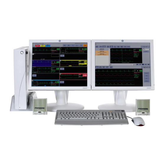
Unity Network will be changed immediately; Unity may appear in some places and CARESCAPE in others. It is important to understand that while the CARESCAPE Network replaces the Unity Network name, they refer to the same GE monitoring network Standard components include the following items: ... -
Page 29: Display
Equipment overview Display You can configure the CIC Pro center to display real-time parameter waveforms and numeric data for one to 16 patients. See Set the Display Configuration (non-mirror CIC Pro centers) on page 6-49. You can also view stored parameter waveforms and numeric data, control windows, and various system level operations. - Page 30 Equipment overview Side view Rack-mount views Front view Back view CIC Pro™ 2026419-033E...
- Page 31 Do not use this port or connect to any device. This port is physically disabled by a dummy plug. CARESCAPE Network MC Interface with other networked GE patient monitoring and telemetry system devices. network connection Display waveform, parameter, and alarm condition data from other networked devices.
-
Page 32: Controls
Equipment overview Controls Mouse Use a standard mouse to select menu options or patient data. Mouse pointer shapes Depending on the operation mode of the CIC Pro center, the mouse pointer changes its appearance. Pointer Function Arrow: Indicates the CIC Pro center is operating in user mode. Use the arrow pointer to select menu options, patient data, and to navigate from window to window. -
Page 33: Power Indicator
Equipment overview Keyboard Use a standard keyboard to type text into a data entry field. NOTE When using the MultiKM software application, you may use one keyboard and one mouse across multiple centralized CIC Pro centers. Typing text into a data entry field To type text into a data entry field, position the mouse pointer over the data entry field. -
Page 34: Secondary Display
Equipment overview Secondary display The secondary display supports patient data review functions and can be configured to display CIC Pro center applications in full screen or half screen formats. Using a secondary display provides more room for real-time patient monitoring in the primary display. -
Page 35: Touchscreen Displays
Equipment overview Touchscreen displays The touchscreen display allows you to select any selectable screen object by gently tapping the object with your finger. The following guidelines apply when using a touchscreen display: Applying tape or other items to the screen impairs the touchscreen’s functionality. -
Page 36: Prn 50-M Digital Writer
Equipment overview NOTE Consult your sales representative or Technical Support for the latest supported printers. PRN 50-M digital writer A PRN 50-M digital writer can be connected to the CIC Pro center to print alarm graphs, control settings, waveforms, events, and trend data. The writer prints reports and graphs on 2-inch wide paper. -
Page 37: Un-Interruptible Power Supply (Ups)
LOSS OF MONITORING — If power to the CIC Pro center is lost, patient monitoring information will no longer be displayed or stored. GE recommends using an un-interruptible power supply with the CIC Pro center. Without a UPS, power line outages may result in: ... -
Page 38: Block Diagram
Equipment overview Block diagram FLASH DRIVE Physiological data CIC Pro centers trend two types of physiological data: periodic and episodic. Periodic data Periodic data is constantly updated. Data is sampled every two seconds to yield 30 samples per minute. The displayed value is the median of the 30 samples. It is always the median of a one-minute time frame, regardless of the interval selected. -
Page 39: File And Data Management
Equipment overview File and data management Log files Log files generated by the CIC Pro center application, other associated applications, and the CIC Pro center operating system are used during system analysis, problem diagnosis, and troubleshooting. See Access log files on page 10-14 for more information. -
Page 40: Licensing
Equipment overview Licensing All features and functions of the CIC Pro center are determined by the licenses activated and running on each CIC Pro center. Licenses are specific to each individual CIC Pro center’s serial number, are node locked, and cannot be used (floated) by another CIC Pro center. - Page 41 Equipment overview Stores 72 hours of data per patient regardless of license type. Licensing controls amount of data that is viewable. Unit Licensing Mode sets which type of license is requested. Supported types: None (default - 1 hour), 24, 48, 72 hours. ...
- Page 42 Equipment overview If a NO COMM condition exceeds the Offline Storage setting time frame, all data for the bed is deleted. If (while in Auto mode) the bed comes back online (the NO COMM condition ends) after this point, the bed is reassigned as a new and different bed and new data collection is started for the bed.
- Page 43 Equipment overview Example 2: CICA goes offline and stops collecting full disclosure data on BED1. This causes CICB to begin collecting full disclosure data on BED1. NOTE The master CIC Pro center detects CICA going offline, and switches full disclosure data collection over to CICB, within a minute of the offline event. CICA comes back online after exceeding the Offline Storage setting time frame.
- Page 44 Equipment overview NOTE Combo mode is stopped (breaking Combo mode) by discharging either bed. If this happens, full disclosure data collection continues on the undischarged bed, and the data is stored under the undischarged bed name. NOTE If the hardwired bed is discharged, '*' would again be included in the name. The following are Combo mode examples: Combo mode Example 1: A hardwired bed BED is admitted and full disclosure data is collected.
- Page 45 Equipment overview Combo mode Example 3: A telemetry bed BED* is admitted and full disclosure data is collected. A hardwire bed BED is admitted and full disclosure data is collected. Two separate full disclosure data stores exist, one for each bed (possibly on a different CIC Pro centers).
-
Page 46: Networking
Unity Network will be changed immediately; Unity may appear in some places and CARESCAPE in others. It is important to understand that while the CARESCAPE Network replaces the Unity Network name, they refer to the same GE monitoring network. 2-20 CIC Pro™... -
Page 47: Patient Monitoring Network
Equipment overview Patient monitoring network The CIC Pro center processes and displays real-time data acquired from up to 16 networked GE monitors or telemetry transmitters/transceivers connected to the CARESCAPE Network. When patient data is acquired from ApexPro telemetry transmitters/transceivers (telemetry beds), the data is transmitted to a telemetry receiver where it is then transferred to the CARESCAPE Network via a wired connection. -
Page 48: Patient Data Interface
Equipment overview Web browser intranet web portal WARNING LOSS OF MONITORING — If the browser function is inappropriately used, loss of monitoring function may result. Use alternate monitoring devices or close patient observation until the monitoring function at the CIC Pro center is restored. When using the browser, follow these restrictions: ... - Page 49 Equipment overview Item Description Alarm buttons. Show the care unit name, bed number, and the cause of the alarm. Colored border alarm indicator. The patient window is outlined in red or yellow to identify a patient alarm condition. The alarm message is also displayed. Alarm message.
-
Page 50: Single Patient Viewer
Equipment overview Item Description Empty patient window displaying an Admit window. System status tray. Displays the following icons. MultiKM icon. See Using the MultiKM application on page 2-6. See System resource indicator on page 10-11. Print server queue icon. Single patient viewer The single patient viewer allows you to view detailed real-time or stored parameter data for one patient. -
Page 51: Real-Time Patient Data
Equipment overview Real-time patient data Monitored parameters The CIC Pro center can retrieve and display many different types of parameter data from patient monitors connected to the CARESCAPE Network. It can also retrieve and display many different types of parameter data from secondary devices connected through a Unity Network Interface Device. -
Page 52: Service Interfaces
Equipment overview Tool Description Graphic trends Review parameter numeric data over a specified period of time in bar graph format. Vital signs Review parameter numeric data values for monitored parameters over a selected period of time. Calipers Record measurements on the ECG waveforms. Service interfaces The CIC Pro center provides local, on-site remote, and off-site remote service interfaces for configuring, troubleshooting, and completing some of the checkout... -
Page 53: Licensing
Licensing 2026419-033E CIC Pro™... -
Page 54: Cic Pro Center Configurations
Licensing CIC Pro center configurations License requirements The license requirements for various types of CIC Pro center configurations are listed in the following table. Configuration type Licenses required Diagram Standard CIC Pro center Patient management configuration package Review package with or without FDPR and TDRT, as needed See License packages on page 3-... - Page 55 Licensing Configuration type Licenses required Diagram Mirror CIC Pro center Mirror license set configuration At least patient management package and optionally review package See License packages on page 3- MultiKM configuration View license set on CIC Pro centers in the group ...
-
Page 56: Available Licenses
Licensing Configuration type Licenses required Diagram CIC Pro center with enterprise PDS licenses on CIC Pro solutions: PDS connectivity center (EVPD and TDPD) Patient management package and optionally review package on the primary CIC Pro center See License packages on page 3- ... - Page 57 Licensing Option Name Description Code Secondary Display DDIS View all of the single patient viewer applications in this secondary display. Use the secondary display as a review display. View two single applications at the top and bottom half of the screen. ...
-
Page 58: License Packages
CIC Pro Clinical Information Center Operator’s Manual. License packages For current information regarding the following packages, please contact your local GE representative. The following packages are offered in different combinations within the package and across packages. Package Licenses... -
Page 59: Patient Data Server Information
Licensing Package Licenses Full disclosure license FD24, FD48, FD72 Special options UTMM, UTCX Patient Data Server information When the Events - Patient Data Server or Trends - Patient Data Server licenses are installed, you can select the Events Data Source icon, which can be one of the following icons on the Events Directory screen: Icon Description... - Page 60 Licensing CIC Pro™ 2026419-033E...
-
Page 61: Service Interfaces
Service interfaces 2026419-033E CIC Pro™... -
Page 62: Introduction
Service interfaces Introduction Service interfaces provide several advanced and specialized functions for configuring, troubleshooting, and performing checkout procedures on the CIC Pro center. Access methods The CIC Pro center provides both direct and network access methods to access the service interfaces. Direct access method The direct access method uses locally connected displays, keyboards, and mice to access multiple CIC Pro center functionality. -
Page 63: Operating Modes
Service interfaces Operating modes Overview Normally, the CIC Pro center starts up in the clinical application mode. To switch to administrator mode, refer to Administrator mode access on page 4-3. CAUTION During shutdown or while in administrator mode, beds displayed by the CIC Pro center will be unmonitored if not displayed by a different CIC Pro center. -
Page 64: Service Interface Access
Service interfaces Service interface access Overview WARNING CIC Pro center service interfaces are intended for use only by properly trained, qualified personnel. Do not “experiment” with the service utilities, or use them in any way other than shown in this manual. -
Page 65: Setup Cic With Service Access
Service interfaces The password for the Webmin logon can be changed from the default at the first logon. However, the password can only be reset by GE personnel who are physically at the site, or remotely if the device is Insite ExC (Remote) connected. -
Page 66: Windows Utilities Access
Service interfaces Windows utilities access Once you Log on to the CIC Pro center as Administrator on page 4-3, there is no additional login required to access the Windows utilities. Screen-sharing interface access Log on to the screen-sharing interface Install the Ultra VNC client, distributed via the CIC v5.1.x Distribution software DVD, onto the service PC. -
Page 67: Webmin Interface Access
Service interfaces Webmin interface access CAUTION Users must log off of Webmin to prevent unauthorized access. Closing Webmin is not equivalent to logging off. You must click Logout. You can access the Webmin service interface locally from the CIC Pro center, or remotely from a service PC connected to the CARESCAPE Network IX network. - Page 68 Service interfaces Windows 2000 Windows XP From the Windows taskbar, select From the Windows taskbar, select Start > Settings > Control Panel > Start > Control Panel > Network Network and Dial-up Connections. Connections. On the Network and Dial-up Right-click Local Area Connection. Connections window, right-click on Select Properties.
-
Page 69: Webmin Overview
Service interfaces In the Address field, type https://[CIC Pro center server IX IP address]:10000 and press Enter. NOTE [CIC Pro center server IP address] is the CARESCAPE Network IX network IP address for the CIC Pro center server. Make sure you type https and not http. -
Page 70: Configuration Tab
Service interfaces Option Function OS Hotfix Information View a list of installed service packs. Printer Information View information about the installed digital writers and laser printers. See Check status of installed printers on page 7-3. System Information View the serial number, model ID, and software version corresponding to the CIC Pro center. - Page 71 Service interfaces Option Function Asset Settings Set the Device Asset Number to identify this device on the CARESCAPE Network. View the Device Serial Number. See Check asset information on page 7-21. Backup/Restore Back up and restore certain tools, data files, and list files. Back up and restore the CIC Pro center configuration on page 6-71.
-
Page 72: Diagnostics Tab
Service interfaces Option Function Set Flags Configure the following settings: No Comm. See Configure the NO COMM alarm setting, if applicable on page 6-22. Force Age. See Configure force age setting, if applicable on page 6-23. Multiviewer Alarm Audio. See Configure multiviewer alarm audio setting, if applicable on page 6-24. - Page 73 Service interfaces Option Function Ping Test the CIC Pro center’s connectivity with other network devices. See Unable to communicate with a device on page 8- Preventative Access a wide variety of system tests. Maintenance Runtime Diagnostics Access a wide variety of system status information. SMART Drive Status View the read and write integrity of the storage media devices.
- Page 74 Service interfaces 4-14 CIC Pro™ 2026419-033E...
-
Page 75: Installation
Installation 2026419-033E CIC Pro™... -
Page 76: Requirements
A site survey with all network design, installation, and testing must be completed and documented prior to equipment installation. The site survey is completed by authorized GE personnel. Service PC A PC is required for licensing. This can be a desktop or a laptop computer. -
Page 77: Format A Usb Memory Stick
Installation Format a USB memory stick To activate licenses with a USB memory stick, you need an NTFS formatted USB memory stick containing the <Serial Number of CIC Pro center>.txt license file, matching the serial number of your CIC Pro center. Insert the blank USB memory stick into one of the service PC’s USB ports. -
Page 78: Gather Required Tools
When installing a CIC Pro center into a care unit, you need to verify that the CIC Pro center’s platform and software are compatible with all devices on the MC and IX network. Notify the biomedical staff if any non-GE equipment is installed on the MC and IX network. - Page 79 CAUTION NEGLIGENCE — GE does not assume responsibility for damage to the equipment caused by improperly vented cabinets, improper or faulty power, or insufficient wall strength to support equipment mounted on such walls.
- Page 80 Installation Do not remove the bottom feet or operate with the bottom of the unit on a carpeted surface. If installed with the vent holes in the bottom surface to the side (standing on a side, or vertical installation), a minimum of 1 centimeter (3/8 inch) clearance must be provided between the vent holes and the adjacent surface.
- Page 81 If power to the CIC Pro center is lost, patient monitoring information will no longer be displayed or stored. GE recommends using a UPS with the CIC Pro center. See Accessories on page 9-6 for a listing of UPS units available for the CIC Pro center. Follow the manufacturer’s recommendations for installing the UPS.
-
Page 82: Installation Process
Both hard-wired and telemetry beds are limited in the number of remote view connections that can be supported. There are limitations for the device quantity supported by the CARESCAPE Network. Please contact GE for guidance on CARESCAPE Network construction. CIC Pro™... - Page 83 WARNING Only external devices specifically designed to be connected to the CIC Pro center, or approved by GE for use with the CIC Pro center, should be connected, as specified in this manual or as otherwise specified by the manufacturer.
-
Page 84: Installation Process Checklist
Installation CAUTION POWER REQUIREMENTS — Before connecting the device to the power line, check that the voltage and frequency ratings of the power line are the same as those indicated on the unit’s label. If this is not the case, do not connect the system to the power line until you adjust the unit to match the power source. -
Page 85: Mount The Equipment
The standard keyboard is supplied with a 6-foot cable, so only an additional 9-foot USB passive extender can be used. GE does not carry in service stock any USB extenders. No extenders are supported for the speaker. ... -
Page 86: Connect The Cables And Peripheral Devices
Installation Connect the cables and peripheral devices CAUTION Do not insert the CARESCAPE Network IX or CARESCAPE Network MC cable into the CIC Pro center at this time. Network connectivity is enabled after the CIC Pro center has been installed and configured for use. -
Page 87: Connect The Display(S) On Page
OFF. All clinical setting values must be received from the GE Clinical Application Specialist (CAS) or from the nursing director of the care unit. Consult with your CAS or hospital staff about the use of the various alarms in your environment and the configuration of the alarm audio settings. - Page 88 Installation Non-touchscreen primary display Touchscreen primary display Insert the single display DVI cable into Insert the touchscreen monitor DVI the primary video DVI port (DVI-I 1) on cable into the primary video DVI port the CIC Pro center. (DVI-I 1) on the CIC Pro center. Firmly screw in the DVI connectors into Firmly screw in the DVI connectors into the connector port.
-
Page 89: Remote View (View Only)
The Black Box CAT-5 VGA video splitter as described in this section is supported with the 20-in NEC 2090UX black LCD display (pn2030604-002) as supplied by GE or equivalent. If an equivalent display is used, ensure the selected display is compatible with the Black Box CAT-5 VGA video splitter. -
Page 90: Install Optional Accessories
Installation Installation instructions are included with the kits specified. CAT 5 UTP cable Install optional accessories Install laser printers Before installing a laser printer, determine if connecting using USB or the network. For a list of compatible USB and network printers, refer to Laser printer on page 2-9. -
Page 91: Connect The Digital Writer On Page
Installation printer. To do this, use the controls and appropriate manufacturer’s instructions enclosed with the printer. For configuration information, refer to Configure USB laser printers on page 6-28 Configure network laser printers on page 6-14. Connect the digital writer NOTE The PRN 50-M must use software v2B or later to operate properly with the CIC Pro center and telemetry systems. -
Page 92: Plug In The Power Cable To The Cic Pro Center
Installation Remove the old spool and install a new paper roll so it unrolls from the bottom. Close the door. Make sure the paper protrudes from the opening. Test the writer by initiating a graph strip. Remove the test graph by tearing downward. Plug in the power cable to the CIC Pro center WARNING Ample access for AC power cord disconnect (from the wall outlet,... -
Page 93: Turn On The Power
Installation Turn on the power Turn on the power by pressing the power switch located on the CIC Pro center and on the displays. A green power indicator illuminates when the power is turned on. After approximately 30 seconds, the multi-patient viewer should display. Proceed to Configuration on page 6-1. - Page 94 Installation 5-20 CIC Pro™ 2026419-033E...
-
Page 95: Configuration
Configuration 2026419-033E CIC Pro™... -
Page 96: Pre-Configuration Process
Configuration Pre-configuration process Pre-configuration requirements All the CIC Pro centers connected to the CARESCAPE Network IX and MC networks must comply with the following configuration requirements: All devices must have the same time zone settings. The Automatically adjust clock for daylight saving changes check box must remain UNCHECKED at all times. - Page 97 (within one minute or less) used by the existing GE devices on the CARESCAPE Network. Run the Check Centrals utility to verify that the time zone, IP addresses, and subnet mask are configured correctly.
- Page 98 Configuration NOTE The information in the sample output represents the data format only. Therefore, do not attempt to analyze these IP addresses versus any errors reported. --- Results for checkCentrals -tz --- Gathering Central Station information currently on the Unity network.....UU..U..
- Page 99 Investigate if there is any unauthorized, non-GE medical equipment connected to the MC/IX network. If any unauthorized non-GE equipment is found or reported to be connected to the CARESCAPE Network, read and understand the following Warning and communicate this information to the hospital IT/...
- Page 100 This increased risk comes about because GE has not been able to review/approve the proposed network design and/or commission the implemented network to ensure it meets required performance specifications.
-
Page 101: Configuration Process Checklist
Configuration NOTE In the hierarchy of multiple compatible CIC Pro center hardware and software versions that co-exist, it is important to assign a set of the highest MC IP addresses to the highest software version. For example, if you are installing CIC v5.1.x to an existing CARESCAPE Network comprising of CIC v4.0.7 or later, you must allocate a set of the highest MC IP addresses to all of the CIC Pro center’s hardware running CIC v5.1.x. -
Page 102: Configure Desktop-Related Settings
Pro center on page 8-30 Configure clinical application settings NOTE All clinical setting values must be received from the GE Clinical Application Specialist (CAS) or from the nursing director of the care unit. Configure USB laser printers on page 6-28. -
Page 103: Reconnect The Cic Pro Center With The Network
Configuration Configure the printer settings on page 6-36. Set the CIC Defaults on page 6-36. Set the Telemetry Unit Defaults on page 6-44. Set the Telemetry Alarm Control Defaults on page 6-45. Set the full disclosure defaults on page 6-47. -
Page 104: Run Log File Compression Configuration Utility
Configuration During CIC Pro center v5.1 configuration after software re-image/ reload process Run Log File Compression Configuration Utility on page 6-88 Disconnect from the CARESCAPE Network IX and MC networks It is important that you disconnect the CIC Pro center from the CARESCAPE Network IX and MC networks before you begin the configuration process. - Page 105 Configuration Item Description License Name The licensing options available for activation. Serial number The serial number of this CIC Pro center. Activation Code The activation code for each license activated on this CIC Pro center. A license is activated when an activation code displays and the activation icon appears green in color.
-
Page 106: Set The Network Ip Address
Configuration If the path shown is incorrect, navigate to the directory on the USB memory stick where the <Serial Number of CIC Pro center>.txt file is stored and click Open. After a short delay, a message displays. Click OK. The Licensing window on the CIC Pro center should now display the option activation codes for the activated licenses. - Page 107 Configuration Get the completed site survey workbook for this care area. If you have not already logged onto Webmin, Log on to the Webmin service interface on page 4-7. Click Configuration > Network. Under Unity MC, if the site uses a custom CARESCAPE Network MC network addressing scheme, change the CARESCAPE Network MC network IP address so that it is unique on the network.
-
Page 108: Configure Clinician Review Workstation
Configuration NOTE DNS addresses can be used for browser sources and for InSite 2.0 configuration only. Click Save. NOTE You must save the changes or the changes will be lost. Complete any other pending CIC Pro center configuration procedures, as required. - Page 109 Configuration With the laser printer physically connected to the CARESCAPE Network IX network, turn on the power to the laser printer. Click Install Laser Printer. In the Printer’s IP Address field, type the IP address assigned to the printer. NOTE It is recommended that the assigned IP addresses of the printers be maintained at the site for future reference.
-
Page 110: Configure The Server For Remote Connectivity
Deleting a printer does not remove the references to it under the CIC Setup/ care unit default settings. Configure the server for remote connectivity The CIC Pro center is capable of remote service using GE Healthcare InSite ExC Digital Services. See the site survey workbook for required configuration information. - Page 111 Remote Service Configuration settings are automatically populated. Remote Service Configuration Parameter Value Notes System ID Identifies the system to the GE backoffice servers. These values are read-only and are unique. Serial Number Identifies the unit and is set at the time of manufacture.
- Page 112 Remote Desktop Enable a remote screen-sharing This a view-only option. If No for a GE Technical Support view is selected, then GE Technical of the two clinical displays for Support will not be able to view diagnosing problems with the CIC the displays.
-
Page 113: Set Up A Citrix Client
Citrix is an application that runs on top of Microsoft’s Terminal Services in the Windows 2003 server. Citrix servers run applications, such as Notepad, Internet Explorer, GE software, or the hospital’s proprietary applications. CIC Pro center v5.1.x software is included with a Java Citrix client. Citrix clients display the applications and pass keyboard, mouse, and sound events back and forth to the Citrix server. - Page 114 Configuration On the Citrix Configuration window, type the configuration information in the applicable fields. Field name on Citrix Field description Configuration window User Name The values as dictated by the Citrix application. The hospital IT Administrator can supply these values. Password Server Address This value corresponds to the TcpBrowserAddress in the sample...
-
Page 115: Configure Browser Favorites
Configuration Configure browser favorites Define browser favorites NOTE Before the browser can access internet web addresses (external to the hospital network), a connection for the CARESCAPE Network IX network to the internet is required. Contact the hospital IT Administrator. If you have not already logged onto Webmin, Log on to the Webmin service interface on page 4-7. -
Page 116: Configure Set Flags Settings
CIC Pro center. NOTE All clinical setting values must be received from the GE Clinical Application Specialist (CAS) or from the nursing director of the care unit. Consult with your CAS or hospital staff about the use of these functions and if they should be used with your configuration. - Page 117 Configuration NOTE If the NO COMM is set to DISABLE, a visual only indicator will appear in the multi-patient viewer window at the CIC Pro center. The clinical user will not receive an audible notification. DISABLE is the factory default setting. ...
- Page 118 Configuration NOTE All clinical setting values must be received from the GE CAS or from the nursing director of the care unit. Consult with your CAS or hospital staff about the use of these functions and if they should be used with your configuration.
- Page 119 Configuration CAUTION OUT-OF-UNIT ALARMS — If the CIC Pro center is configured to alarm for out-of-unit alarms, any patient displayed on that out-of- unit CIC Pro center, and is alarming, can have their alarms silenced from the out-of-unit CIC Pro center. Complete the following procedure to configure the Multiviewer Alarm Audio setting on the CIC Pro center: If you have not already logged onto Webmin,...
- Page 120 Configure ADU alarm audio setting, if applicable NOTE All clinical setting values must be received from the GE CAS or from the nursing director of the care unit. Consult with your CAS or hospital staff about the use of these functions and if they should be used with your configuration.
-
Page 121: Configure The Cic Pro Center Language
Configuration Option Description Enable Enables any ADU buttons audible alarms for any out-of-unit patient displayed in a multi-patient viewer window at the CIC Pro center. Disable Disables any ADU buttons audible alarms for any out-of-unit patient displayed in a multi-patient viewer window at the CIC Pro center. Click Submit. -
Page 122: Configure Desktop-Related Settings
Configure network laser printers on page 6-14. Configure HP LaserJet 2430 and HP LaserJet P3005 USB printers MP100 series hardware running CIC Pro center v5.1.x software supports the HP LaserJet 2430 and HP LaserJet P3005 printers as plug and play USB printers. When 6-28 CIC Pro™... -
Page 123: Configure Hp Laserjet P3015 Usb Printers
CIC Setup. Configure HP LaserJet P3015 USB printers MP100 series hardware running CIC Pro center v5.1.x software supports the HP LaserJet P3015 printer as a plug and play USB printer and as a Network printer. This printer, when used as a USB printer, requires special installation/configuration as described in this section. -
Page 124: Set The Laser Printer Default Paper Size
Configuration Set the laser printer default paper size NOTE The CIC Pro center leaves the factory with the default paper size set to 8 x 11 inches (letter). Log on to the CIC Pro center as Administrator on page 4-3. From the Windows taskbar, click Start >... - Page 125 Configuration Click the display 2 icon. NOTE If required, drag and drop the display icons into the same orientation as the physical setup. Select the Extend my Windows desktop onto the monitor option and click Apply. The desktop expands onto the secondary monitor. NOTE The secondary monitor displays a mirror image of the primary monitor display when the Extend my Windows desktop onto the monitor option...
-
Page 126: Calibrate A Touchscreen Display
Configuration Select the Apply the new display settings without restarting option and click Click OK to close the Display Properties window. m. Perform Screen calibration on page 6-55. Calibrate a touchscreen display Touchscreen display video drivers Calibrating a touchscreen display adjusts the accuracy of the touchpoint on the display used to select an item. - Page 127 The 20” NEC display supports single touch only, even though enough USB ports are available at the CIC Pro center. The 19” GE medical grade display supports USB and serial COM1 port dual touch. Touchscreen calibration using the Elo application...
-
Page 128: Set The Time Zone
Configuration When all of the connected touchscreen displays are calibrated, click OK from the Elo Touchscreen Properties window. Touchscreen calibration using the Touchware application If a single display is connected to the CIC Pro center If you have a secondary display connected to the CIC Pro center, you must disconnect it before calibrating the primary display. - Page 129 Configuration Verify the Automatically adjust clock for daylight saving changes box is not checked. CAUTION DATA CORRUPTION—Do not select the Automatically adjust clock for daylight saving changes check box. You must manually make Daylight Saving Time changes in the monitoring system. This change may affect the CARESCAPE Network time and date parameter of some patient data and FD data corruption.
-
Page 130: Restart Cic Pro Center
Configuration Restart CIC Pro center NOTE If you have completed Set the time zone on page 6-34, it is not necessary to restart the CIC Pro center again at this point. Restart the CIC Pro center. From the Windows taskbar, click Start > Shutdown > Restart and press Enter. - Page 131 Configuration WARNING QUALIFIED PERSONNEL — The Service mode is intended for use only by qualified personnel with training and experience in its use. The consequences of misuse include loss of alarm configuration, loss of patient data, corruption of the CIC Pro center operating system software, or disruption of the CARESCAPE Network.
- Page 132 Make sure no other central stations have the same central name in the same care unit. All other systems on the GE CARESCAPE Network MC network use the Central name to identify this CIC Pro center system. The central name should be relevant to the location, such as CS2 or SDU3.
- Page 133 Repeat this verification periodically, including a check of all connected speakers. NOTE All clinical setting values must be received from the GE Clinical Application Specialist (CAS) or from the nursing director of the care unit. Consult with your CAS or hospital staff about the use of these functions and if they should be used with your configuration.
- Page 134 Repeat this verification periodically, including a check of all connected speakers. NOTE All clinical setting values must be received from the GE Clinical Application Specialist (CAS) or from the nursing director of the care unit. Consult with your CAS or hospital staff about the use of these functions and if they should be used with your configuration.
- Page 135 Configuration After making your selections, choose one of the following: Click OK or Cancel to apply your changes and close the CIC Setup window. Click Apply to apply your changes without closing the CIC Setup window. Verify the new settings prior to monitoring patients. Mirror another CIC Pro center Overview CAUTION...
- Page 136 Configuration alarms. You can configure the multi-patient viewer alarm audio and ADU window. If the mirror CIC Pro center is v4.1.1 or earlier, alarms will be visible but not audible. If the mirror CIC Pro center is in the same care area, then alarms will be both audible and visible, and it is not version dependent.
- Page 137 Configuration Click the Disable Auto Display Button checkbox in the Auto Display Button section of the Display Configuration tab. Verify all the Display Configuration settings are the same for the main and remote CIC Pro centers. Set the Columns and Rows in the Display Configuration tab of the remote CIC Pro center to match the main CIC Pro center.
-
Page 138: Set The Telemetry Unit Defaults
Configuration Set the Telemetry Unit Defaults This option sets telemetry unit default settings. In user mode, all of the controls on the Telemetry Unit Defaults tab are view-only. You must be in the Service mode to set the Telemetry Unit Defaults at the CIC Pro center. NOTE For more information on setting Telemetry Unit Defaults, refer to the telemetry system’s operator manual. -
Page 139: Set The Telemetry Alarm Control Defaults
Configuration Option Function Default Location for this CIC Set the print location for telemetry bed patient data: Manual: Designate the default manual graph location for telemetry patients. Alarm: Designate the default alarm graph location for telemetry patients. Print WIndow: Designate the default print window location for telemetry patients. - Page 140 Configuration NOTE For more information on setting Telemetry Alarm Control Defaults, refer to the telemetry system’s operator manual. Complete the following procedure to configure the Telemetry Alarm Control Defaults settings: From the multi-patient viewer, click Setup CIC. Log on to Setup CIC with service access on page 4-5.
-
Page 141: Full Disclosure License Management Setup
Configuration After making your selections, choose one of the following: Click OK to apply your changes and close the CIC Setup window. Click Apply to apply your changes without closing the CIC Setup window. Verify the new settings prior to monitoring patients. Full disclosure license management setup Overview Every CIC Pro center with v4.0.x or later software has the ability to store 16 beds of... - Page 142 Configuration On the Full Disclosure Defaults tab, change the settings as needed: Option Function Report: Duration Designate how much data is included in the report. The maximum report duration is 72 hours, depending upon licensing. To set the report duration, move the scroll bar to the left for shorter duration or to the right for longer duration. Report: Hole Location Provide space for binding printed reports.
-
Page 143: Set The Display Configuration (Non-Mirror Cic Pro Centers)
Configuration Option Function Unit License Default: Full NOTE Disclosure License Type If the default does not match the actual license, full disclosure does not work. Display a list of the full disclosure license type. Offline Storage WARNING POTENTIAL DATA LOSS—Do not allow a NO COMM (patient offline) event to exceed the time limit selected in the Offline Storage setting. - Page 144 Configuration NOTE An alarm will sound when removing admitted beds from the display if the beds are not viewed on another CIC Pro center. Complete the following procedure to configure the Display Configuration settings: From the multi-patient viewer, click Setup CIC. Log on to Setup CIC with service access on page 4-5.
-
Page 145: Set The Current Telemetry Listings
Configuration Option Function Auto Display Button Configure the Auto Display button: Maximize Waveform Length: Maximizes the duration of displayed waveforms. Maximize Number of Waveforms: Maximizes the number of displayed waveforms. Disable Auto Display Button: Removes the Auto Display button from the multi-patient viewer menu bar and prevents the use of this function. - Page 146 Configuration On the Current Telemetry Listings tab, change the settings as needed: Option Function Admitted Telemetry Display a view-only system overview of the admitted telemetry patients. Patients NOTE Each row displays information for one telemetry patient (sorted by TTX number). The second line of an entry shows the current software level for the patient bed in question.
-
Page 147: Set Up Locked Beds
Configuration To change an existing hardwire bed, telemetry bed, or telemetry transmitter/ transceiver, complete the following tasks: Use the scroll bar to locate the item you want to change. Click on the item to display an editing window. Press Enter to add the entry to the list. After making your selections, complete one of the following tasks: ... - Page 148 Configuration On the CIC Defaults window under Real-Time BP/NIBP UOM Selection, select kPa. Click Apply to apply your changes without closing the CIC Setup window. The pressure value now displays in kPa. 6-54 CIC Pro™ 2026419-033E...
-
Page 149: Screen Calibration
Configuration Screen calibration CAUTION When using a video splitter with the CIC Pro center, screen calibration may be possible with only one of the monitors connected to the splitter. This is because changing calibration for one monitor will effect the calibration of all other monitors connected to that same splitter. - Page 150 Configuration Under Screen Calibration, click Begin Calibration. The Screen Calibration window displays on the primary display and also the secondary display, if present. 6-56 CIC Pro™ 2026419-033E...
-
Page 151: Browser Configuration
Configuration In the Units field, choose Inches or Centimeters as the unit of measurement you are calibrating to. Click Default to set the display to the default resolution. Hold your ruler horizontally across the computer screen, aligning the zero mark of your ruler with the horizontal zero mark of the screen ruler. - Page 152 Configuration Define the Internet options on page 6-58. Define browser favorites on page 6-21. Navigate the browser The following table identifies the icons you use to navigate the Browser window: Icon Description Return to previous (cached) webpage. Advance to next (cached) webpage. Stop the webpage loading process.
- Page 153 Configuration WARNING LOSS OF MONITORING — If the browser function is inappropriately used, loss of monitoring function may result. Use alternate monitoring devices or close patient observation until the monitoring function at the CIC Pro center is restored. When using the browser, follow these restrictions: ...
- Page 154 Configuration NOTE When Internet Explorer starts, the browser displays the specified Home Page. Click the Connections tab. Under Local Area Network (LAN) settings, click LAN Settings. 6-60 CIC Pro™ 2026419-033E...
-
Page 155: Configure Customize Groupings
Configuration Enter the Automatic configuration script or Proxy server address and port according to the hospital IT Administrator. Click OK. Under Automatic Configuration, uncheck Automatically detect settings and check Use automatic configuration script options. Click OK to close the Local Area Network (LAN) settings window. 10. - Page 156 Configuration In the upper-right corner of the single patient viewer, click From the Customize Graphic Trends menu, click Using the onscreen or external keyboard, enter the name of the custom view (up to 10 characters) and click Enter. The name of the custom view is displayed under Groups on the Customize Graphic Trends menu.
- Page 157 Configuration From the Customize Graphic Trends menu: Under 1 Select parameter, select the parameter label that you want to change. Under 2 Choose action, click Change. On the Select Parameters popup window, select the appropriate parameter, and click Close. 10. Repeat steps for the remaining parameters.
-
Page 158: Set Up Custom Groupings For Vital Signs
Configuration Set up custom groupings for vital signs Log on to Setup CIC with service access on page 4-5. From the multi-patient viewer, select any patient window. Click Patient Data. Click Vital Signs. In the upper-right corner of the single patient viewer, click From the Customize Vital Signs menu, click Using the onscreen or external keyboard, enter the name of the custom view (up to 10 characters) and click Enter. -
Page 159: Configure Shortcuts To Favorite Cic Pro Center Views
Configuration Reposition the parameters in the list as needed: Under Order on the Customize Vital Signs menu, highlight the parameter you want to move to a new position. Under Change Order, click the up or down arrow to move the parameter up or down in the list. - Page 160 Configuration In the popup window, type the text (up to 10 characters) that should appear on the shortcut button, and click OK. Verify the new settings prior to monitoring patients. 6-66 CIC Pro™ 2026419-033E...
-
Page 161: Configure The Print Location Settings For Stored Patient Data
Configuration Configure the print location settings for stored patient data Overview You can configure specific categories of non-real-time patient data to print to a local laser printer or to the bedside patient monitor’s current Print Window configuration. You can also prevent non-real-time patient data from being printed by disabling the CIC Pro center’s menu bar print button. -
Page 162: Set The Time-Of-Day Or The Date
Configuration For each patient data category, select the appropriate option. Refer to the following table. Selection/outcome Patient data category Local Laser Disable Bedside Determined Alarm Control The print button is disabled for Disable the print button located in hardwired beds. the CIC Pro center’s menu bar for Alarm Control. - Page 163 Configuration CAUTION RESTART AFTER ADVANCING THE TIME SETTING — When advancing the time 72 hours or greater, you must restart the CIC Pro center to continue collecting full disclosure data. If you do not restart the CIC Pro center, full disclosure data collection stops and it may also cause other data integrity and CIC Pro center performance issues.
- Page 164 Configuration If this CIC Pro center v5.1.x is the Time If this CIC Pro center v5.1.x is not the Time Master on the CARESCAPE Network: Master on the CARESCAPE Network: While changing time using Webmin, please While changing time using Webmin, please note that only 3 time changes will be note that only 6 time changes will be allowed allowed every 10 minutes.
-
Page 165: Back Up And Restore The Cic Pro Center Configuration
Configuration Back up and restore the CIC Pro center configuration NOTE The backup and restore procedure must only be completed from a remote computer. NOTE The backup portion of this section should be performed at regular intervals, whenever changes are made to CIC Pro center configuration settings, and after each preventative maintenance is performed. -
Page 166: Planning Your Care Unit Defaults Restore Strategy
Configuration Right-click the cic_xxxxxxxxx.cfd link and select Save Target As to save the backup file. Planning your care unit defaults restore strategy NOTE Understand the functionality as described below before you proceed with the restore procedure. NOTE The real-time trend graph setting is not saved during backup. It must be restored manually. - Page 167 Configuration NOTE The CIC Pro center application must be stopped in order to perform a restore. Because configuration data is automatically updated to match other CIC Pro centers found running on the care unit, if other CIC Pro centers are left running, when the restored CIC Pro center application starts back up, some configuration data would be overwritten by the automatic update.
- Page 168 Configuration 11. Verify the new settings prior to monitoring patients. Scenario 2: Add or upgrade a CIC Pro center in a care unit running multiple CIC Pro centers When a CIC Pro center is added to or upgraded in a care unit already running other CIC Pro centers, configuration data common to the care unit is changed in the new or upgraded CIC Pro center, when it starts up, to match the other CIC Pro centers found in the care unit network.
-
Page 169: Backing Up And Restoring Local Custom Default Configuration Settings
Configuration Click Browse to select a backup file from the service PC/remote computer. On the Choose file window, navigate to the directory where a file from a previous backup was saved. Select the backup file, and click Open. The backup file location displays in the Browse field. - Page 170 Configuration If you have not already logged onto Webmin, Log on to the Webmin service interface remotely via the CARESCAPE network IX network on page 4-7. Click Configuration > Backup/Restore > Customize Settings. Click Backup. The default files are temporarily written to the CIC Pro center and are prepared for downloading to your local computer.
-
Page 171: Reconnect The Cic Pro Center With The Network
Configuration Click Browse. On the Choose file window, navigate to the directory where a file from a previous backup was saved. Select the backup file and click Open. The backup file link displays in the Browse... field. Click Upload. After the restore is complete, the message, Customize settings have been restored, is displayed. -
Page 172: Pre-Configure The Cic Pro Centers
Configuration NOTE If you connect more than one mouse to a configured mouse group, always position the additional mice on a flat surface. Otherwise, erratic mouse movements and behaviors may result. NOTE All CIC Pro center devices in the MultiKM group have to be of the same version. ... - Page 173 Configuration Connect a mouse and keyboard to every CIC Pro center in the group. You can remove all but one set once you have configured the keyboard and mouse group. From the primary control CIC Pro center where the mouse and keyboard will remain connected, if you have not already logged into Webmin, Log on to the Webmin service interface on page...
-
Page 174: Configure The Keyboard And Mouse Group
Configuration Repeat step for each CIC Pro center you are configuring into a keyboard and mouse group. Configure the keyboard and mouse group After you have identified the Computer Name and activated the MultiKM license (if required) on each CIC Pro center, you need to configure a keyboard and mouse group. NOTE You cannot enable, disable, or configure the MultiKM application from a remote location. - Page 175 Configuration The Change Configuration window displays the list of computer names of available centralized CIC Pro centers that have the MultiKM application enabled. Since the Change Configuration window is already open, it is not necessary to click the Configure button in Webmin. Verify the computer names of the CIC Pro centers to be added or removed from a group are displayed in the list.
- Page 176 Configuration 10. Click and drag the location of the computer names to match the physical layout of the CIC Pro center displays in this group. NOTE Leave the Hot key field blank. CIC Pro centers with a secondary display will move together. 11.
-
Page 177: Change A Keyboard And Mouse Group
Configuration 12. Click Hide to hide the Multimouse window. 13. Verify that the MultiKM application is running on each CIC Pro center in the keyboard and mouse group: Look for the MultiKM application icon (while the CIC Pro center is running) in the bottom right corner of the display screen. - Page 178 Configuration Repeat the configuration starting with step 5. See Configure the keyboard and mouse group on page 6-80. Divide a mouse and keyboard group into two groups Preliminary steps At any time, you may divide a single mouse and keyboard group into two groups (e.g., Group 1 and Group 2).
- Page 179 Configuration Click Remove. Repeat step to remove additional CIC Pro centers from this group (e.g., E and F). NOTE If any CIC Pro center is taken off of an existing Multimouse group for any reason, you must remove that CIC Pro center from the existing group.
- Page 180 Configuration NOTE CIC Pro centers with a secondary display will move together. Click Finish. A message displays the computer names of the CIC Pro centers the computer is grouped with. Click Hide to hide the Multimouse window. The first group has been created (e.g., Group 1: A, B, and C).
- Page 181 Configuration Verify that the MultiKM application is running on each CIC Pro center in the keyboard and mouse group. If there are problems, see MultiKM issues on page 8-10. Combine two keyboard and mouse groups into one group At any time, you may combine two keyboard and mouse groups into one group: Identify the computer groups you want to combine (e.g., Group 1: A, B, C and Group 2: D, E, F).
-
Page 182: Run Log File Compression Configuration Utility
PC CD drive. NOTE Use the Help link for details on usage, prerequisites and troubleshooting. Click List USB Drive(s) on the GE Patch Distribution Utility window. NOTE The utility displays a message identifying the USB drives that are connected to the service PC. -
Page 183: Run Log Compression Configuration Utility
PC. It is not necessary to take additional steps to safely eject the USB memory stick. Close the GE Patch Distribution Utility window. 10. Remove the Log Compression Configuration Utility software CD from the service PC. - Page 184 Configuration NOTE If no (n) is selected, the installation will stop without the utility being installed and Reconfigure utility aborted by user; Exiting with no action taken will appear. 10. The following screen will be displayed at the successful execution of the utility. NOTE If the utility had been previously installed, the message This CIC has already had the log compressor reconfiguration applied;...
-
Page 185: Complete Configuration Checkout Procedures
Configuration Complete configuration checkout procedures NOTE Close all files before starting the checkout procedures. Before using the CIC Pro center to monitor patients, you must verify proper operation of this device in the patient care and networking environments.Use the following checklist to thoroughly test the system for proper function and operation. - Page 186 Configuration Check successful execution of Log File Compression Configuration Utility on page 7-21. 6-92 CIC Pro™ 2026419-033E...
-
Page 187: Checkout Procedures
Checkout procedures 2026419-033E CIC Pro™... -
Page 188: Safety Tests And Checkout Procedures
Test equipment The safety tests and checkout procedures are written for the GE recommended test equipment listed for each test. If you use test equipment other than those GE recommends, you may need to slightly modify some test steps. CIC Pro™... -
Page 189: Configuration Checkout Procedures
Checkout procedures Configuration checkout procedures NOTE All Webmin modules are static in nature. Since the Webmin service interface session times out after 15 minutes, you must always refresh the browser to load the latest page. Check the unit defaults Confirm the unit defaults match the customer’s needs as provided by the clinical application specialist or the responsible hospital care nurse. -
Page 190: Check Operation Of The Secondary Display
Checkout procedures Check operation of the secondary display If you have just restarted the CIC Pro center and turned on the power to the primary and secondary displays, the secondary display should be illuminated and appear grey in color. From the multi-patient viewer, click Browser. The Browser window should appear in the secondary display. -
Page 191: Verify Settings With Check Centrals Command
Checkout procedures Activation code summary sheet CIC Setup > Licensing window Verify settings with Check Centrals command After introducing the upgraded or new CIC Pro center onto a verified compatible IX/ MC network, it is recommended that you run the Check Centrals diagnostic from the CIC Pro center via Webmin as a final checkout. - Page 192 NOTE All clinical setting values must be received from the GE Clinical Application Specialist (CAS) or from the nursing director of the care unit. Consult with your CAS or hospital staff about the use of the various alarms in your environment and the configuration of the alarm audio settings.
-
Page 193: Check Operation Of Audible Alarm Tones
Operating Room mode. NOTE All clinical setting values must be received from the GE Clinical Application Specialist (CAS) or from the nursing director of the care unit. Consult with your CAS or hospital staff about the use of these functions and if they should be used with your configuration. -
Page 194: Check The Pressures Unit-Of-Measure
Checkout procedures Check the pressures unit-of-measure In the multi-patient viewer window, verify that the pressure value displays in the following unit-of-measure: kPa if the language of the CIC Pro center is set to Chinese mmHg if the language of the CIC Pro center is set to any language other than Chinese Check the custom groupings for patient data In the single patient viewer window, verify that the custom groupings display... -
Page 195: Check Full Disclosure License Type For All Admitted In-Unit Beds
Checkout procedures Verify that the following settings listed on the Set Flags Module window are correct: No COMM Force age Multiviewer alarm audio ADU alarm audio Check full disclosure license type for all admitted in-unit beds If you have not already logged onto Webmin, Log on to the Webmin service interface on page... -
Page 196: Save Backup Defaults File On The Usb Memory Stick
Checkout procedures Print a one-hour full disclosure report. Set the Start and End time. Set the Time Per Line time duration. Click Print. Verify the full disclosure report printed out at the printer. Repeat for every CIC Pro center in the care unit. Save backup defaults file on the USB memory stick Ensure that you have backed up the CIC defaults file on the USB memory stick. -
Page 197: Check Usb Devices
Checkout procedures Ensure that there are no errors. If errors are found, refer to Troubleshooting on page 8-1. If you require additional information or troubleshooting assistance, contact Technical Support. Check the C:\ drive: Type c: and press Enter. At the C:\> prompt, type chkdsk and press Enter. Ensure that there are no errors. -
Page 198: Check Internal Hardware Temperature And Voltage Status
Checkout procedures Verify all connected USB devices are shown (e.g., keyboard, mouse, USB printer). NOTE The value 8 in the NumberOfPorts field corresponds to 2 internal ports which are not used and 6 external physical ports. Check internal hardware temperature and voltage status If you have not already logged onto Webmin, Log on to the Webmin service interface on page... -
Page 199: Check Comm Ports
Checkout procedures Property Value Acceptable limits System Voltage (5V) Actual real-time voltage of the CIC Pro 4850 — 5250 mV center’s 5-volt internal power sub- system. System Voltage (12V) Actual real-time voltage of the CIC Pro 11400 — 12600 mV center’s 12-volt internal power sub- system. -
Page 200: Check Drive Operation Information (Flash Drive And Hard Drive)
Checkout procedures Verify that the following information displays in the BIOS Version field on the Bios Information screen: Phoenix - AwardBIOS v6.00PG Phoenix - AwardBIOS v6.00PG Check drive operation information (Flash drive and hard drive) If you have not already logged onto Webmin, Log on to the Webmin service interface on page 4-7. - Page 201 Checkout procedures Flash drive information NOTE This software currently does not support a temperature reporting feature for the flash drive. Therefore, the zeroes which are displayed in the Drive Temperature section do not reflect the actual temperature. Scroll down to view the hard drive information. Hard drive information 2026419-033E CIC Pro™...
-
Page 202: Check Audio Component Operation
Checkout procedures Check audio component operation NOTE The CIC Pro center application must be stopped before conducting this test. CAUTION During shutdown or while in administrator mode, beds displayed by the CIC Pro center will be unmonitored if not displayed by a different CIC Pro center. -
Page 203: Check Speaker Status
Checkout procedures View the results on the Audio Test screen and verify a beeping tone sounds from the CIC Pro center. Check speaker status If you have not already logged onto Webmin, Log on to the Webmin service interface on page 4-7. -
Page 204: Check Operation Of The Watchdog Countdown Function
Checkout procedures Property Value External Speaker Plugged (1) indicates connector is plugged into the external Status speaker socket. Unplugged (0) indicates nothing is plugged into the external speaker socket. Internal Speaker Plugged (1) indicates connector is plugged into the internal Status speaker socket. -
Page 205: Check Processor Fan Status
Checkout procedures Check processor fan status If you have not already logged onto Webmin, Log on to the Webmin service interface on page 4-7. Click Diagnostics > Preventative Maintenance > Fan Test. On the Fan Testing screen, verify the following values are within acceptable limits: Property Value... -
Page 206: Check Integrity Of System Files
Checkout procedures Verify all colors pass the test. Check integrity of system files If you have not already logged onto Webmin, Log on to the Webmin service interface on page 4-7. Click Diagnostics > Preventative Maintenance > Store Integrity Test. Ensure that there are no extra, invalid, or missing files. -
Page 207: Check Asset Information
Checkout procedures Check asset information If you have not already logged onto Webmin, Log on to the Webmin service interface on page 4-7. Click Configuration > Asset Settings. If needed, in the Change Value To field, type the asset ID for the device and click Submit. - Page 208 Checkout procedures 7-22 CIC Pro™ 2026419-033E...
-
Page 209: Troubleshooting
Troubleshooting 2026419-033E CIC Pro™... -
Page 210: Overview
A systematic approach to the diagnosis of problems, as well as a general understanding of the hardware and software architecture of the CIC Pro center are essential to ensure successful troubleshooting. GE recommends formal service training before repairs are attempted. These troubleshooting procedures combined with training provide the service technician with skills necessary to service and repair this device, in the event of a malfunction. - Page 211 First Boot Device — USB-HDD Second Boot Device — HDD-2 Third Boot Device — IBA GE Slot 010 Picklist server is not available The server is not present on the Contact your Information Technology network.
- Page 212 CIC Pro center to be as Run lw -s time to identify the Time close as possible to the CARESCAPE Master on the network. Network time on any existing GE bedside device or CIC Pro center. Using the results of steps 1 and 2, ...
- Page 213 Troubleshooting Message/Symptom/Issue Probable cause Recommended action Time does not advance or alternates Verify Aware Gateway settings: frequently between two or more times - Check if there are one or more Aware continued. Gateways connected to the CARESCAPE Network. If there is one or more Aware Gateways on the network.
- Page 214 Troubleshooting Message/Symptom/Issue Probable cause Recommended action Alarms are silenced for out-of-unit beds at Even though the setflags option Since this capability exists on the CIC Pro the CIC Pro center all_mvaudio is set to on at the central center, care must be exercised not to station, alarms may have been silenced.
- Page 215 Troubleshooting Message/Symptom/Issue Probable cause Recommended action Need to find out current system settings See Display current system settings on related to NO-COMM, Force Age, multi- page 8-14. patient viewer Audio, ADU alarm Audio Unable to access ADT information More than one ADT system on the Network See Admit Request Info button on page 8- Experiencing waveform dropout RF or Network connectivity issues...
-
Page 216: Display Issues
Troubleshooting Message/Symptom/Issue Probable cause Recommended action During CIC reboot, the display screen A USB device other than a keyboard or Remove/unplug USB memory stick from the shows a blank screen with the cursor mouse is connected to the CIC Pro center back of the CIC Pro center and power cycle blinking the CIC Pro center using the power switch. -
Page 217: Red Screen
Troubleshooting until you turn off the power to the CIC Pro center and then turn the power back on. The monitoring function should resume in approximately 90 seconds. Red screen Indicates the CIC Pro center application is restarting itself and patient monitoring at the CIC Pro center is not occurring. -
Page 218: Digital Display Writer
Troubleshooting Try printing a test page on the printer. Digital display writer Check if the printer is powered up. Check if the printer door is closed. Check if the printer has a paper roll. Check the configuration of this printer in the CIC Setup and bedside graph locations. -
Page 219: Cic Pro Center Setup Issues
Troubleshooting On the MultiKM Configuration screen, click Configure. In Other Computers on the Change Configuration window, click the CIC Pro center that has a failed MultiKM license and click Remove to remove this CIC Pro center from the group. Click Hide to hide the Multimouse application window. Use the hotkey Ctrl + F1 to change the focus to the CIC Pro center where the keyboard and mouse is connected. -
Page 220: List Full Disclosure Beds
Troubleshooting In the Address to Ping field, type the IP address of a known device on the network and click Ping. If you receive a reply, then you are able to connect to the device. If you do not receive a reply, perform a network integrity check. Run the Check Centrals utility and resolve any configuration errors. -
Page 221: Set Full Disclosure Mode
Troubleshooting Set full disclosure mode NOTE You cannot change the full disclosure mode while the clinical application is running. Stop the CIC Pro center application. From the multi-patient viewer, click Setup CIC. Click the Service Password tab. Type mms_com as the password and press Enter. At the Windows command line prompt, type stop and press Enter. -
Page 222: Ping Full Disclosure Server
Troubleshooting Ping full disclosure server If you have not already logged onto Webmin, Log on to the Webmin service interface on page 4-7. Click Diagnostics > Ping. Type the address of the full disclosure server process you want to ping, in the format: ["UNIT|CIC"... -
Page 223: Enable Alarms
Troubleshooting Enable alarms WARNING CIC Pro center audible alarms will not sound for patients with bedside monitoring devices configured to Operating Room mode. For instructions on enabling alarms, refer to the following procedures: Configure multiviewer alarm audio setting, if applicable on page 6-24 ... -
Page 224: Require Age Selection For Admit
Troubleshooting Option Function Enable (TTX only) Display only telemetry indicators. Enable (all) Display all waveform indicators. Disable Remove all waveform indicators. Click Submit. If the waveforms are one of the colors listed in the following table, contact Technical Support. Waveform color Interpretation Yellow Missing data from the transmitter. - Page 225 Troubleshooting If you would like to configure the system via a service PC, complete the steps to set up the service PC’s network properties on page and connect a crossover cable from the service PC’s Ethernet port to the CIC Pro center’s IX network port.
- Page 226 Troubleshooting WARNING LOSS OF MONITORING — Provide alternate patient monitoring or close observation before performing the system resource reset procedure. Beds displayed on the CIC Pro center will not be monitored during the system resource reset. After system resource reset is complete and the monitoring function at the CIC Pro center has been restored (about 30 seconds), verify the correct monitoring state and alarm function.
-
Page 227: Time Zone, Daylight Saving Time Setting, And Network Time Issues
Troubleshooting Repeat step and step until you have activated all of the purchased licenses. Store the Activation Code Summary Sheet in a safe and accessible location. In the event of a hard drive failure, the option activation codes are required for disaster recovery. -
Page 228: Log Files
The system resource indicator changes to red until this condition is resolved. Log files Download log files When you contact GE Service, you may have to provide required log file information. If you have not already logged onto Webmin, Log on to the Webmin service interface on page 4-7. -
Page 229: Access Current Log Files
To collect logs for today (current day), refer to Access current log files on page 8-21. Send this log file to GE Service for further investigation. Access current log files This feature allows the user to download the current day’s log files, which include up to a total of 60 days. - Page 230 Troubleshooting Click Download Logs. Click Package Current Logfiles. The job status information is displayed on the Download Logs window. A link to the current log files is added to the list of Archived Logs. 8-22 CIC Pro™ 2026419-033E...
-
Page 231: Application Logs
Troubleshooting Right-click the log file (in the format yyyymmdd_hhmmsssc.bfp) and select Save Target As to save the log file. Send the log files to GE Service for further investigation. Application logs If you have not already logged onto Webmin, Log on to the Webmin service interface on page 4-7. -
Page 232: Operating System Event Logs
Troubleshooting Select the log files you want to view and click View Selected Files. NOTE To select multiple files, hold down the Ctrl key and click the files you want to view. Operating system event logs If you have not already logged onto Webmin, Log on to the Webmin service interface on page 4-7. -
Page 233: Operating System Dr. Watson Log
Troubleshooting Operating system Dr. Watson log If you have not already logged onto Webmin, Log on to the Webmin service interface on page 4-7. Click Diagnostics > Logfiles > View OS Dr. Watson Log. Webmin action log If you have not already logged onto Webmin, Log on to the Webmin service interface on page 4-7. -
Page 234: Access Additional Runtime Diagnostic Information
Troubleshooting Access additional runtime diagnostic information Device driver information If you have not already logged onto Webmin, Log on to the Webmin service interface on page 4-7. Click Diagnostics > Runtime Diagnostics > Device Driver Info. Network information If you have not already logged onto Webmin, Log on to the Webmin service interface on page 4-7. -
Page 235: Operating System Runtime Statistics
Troubleshooting Operating system runtime statistics If you have not already logged onto Webmin, Log on to the Webmin service interface on page 4-7. Click Diagnostics > Runtime Diagnostics > OS Runtime Stats. 2026419-033E CIC Pro™ 8-27... -
Page 236: Operating System Service Process Information
Troubleshooting Operating system service process information If you have not already logged onto Webmin, Log on to the Webmin service interface on page 4-7. Click Diagnostics > Runtime Diagnostics > OS Service Process Info. Process information If you have not already logged onto Webmin, Log on to the Webmin service interface on page 4-7. -
Page 237: Time Zone Information
Troubleshooting Time zone information If you have not already logged onto Webmin, Log on to the Webmin service interface on page 4-7. Click Diagnostics > Runtime Diagnostics > Timezone Info. SMART drive status Self-Monitoring, Analysis, and Reporting Technology (SMART) is a monitoring system for computer hard disks to detect and report various indicators of reliability. -
Page 238: Perform Safe Restart Of The Cic Pro Center
Troubleshooting From the SMART Drive Status window, select the drive from the drop-down list and click Show. Click on either the Run Short Self Test or the Run Extended Self Test button, depending on the test you want to execute. NOTE ... -
Page 239: Perform Safe Shutdown Of The Cic Pro Center
Troubleshooting CAUTION During shutdown or while in administrator mode, beds displayed by the CIC Pro center will be unmonitored if not displayed by a different CIC Pro center. CAUTION Stored data is never the latest data. Therefore, you must first verify the contents. -
Page 240: Change The Logon Password For Webmin
Troubleshooting Change the logon password for Webmin If you have not already logged onto Webmin, Log on to the Webmin service interface on page 4-7. Click Configuration > Passwords. On the Edit User Password window, type the new password in the Password field. -
Page 241: Field Replaceable Units (Frus)
Field replaceable units (FRUs) 2026419-033E CIC Pro™... -
Page 242: Exploded Views
Field replaceable units (FRUs) Exploded views Desktop Power supply FRU Front bezel Speakers Fans CIC Pro™ 2026419-033E... - Page 243 Field replaceable units (FRUs) Hard drive Flash drive 2026419-033E CIC Pro™...
-
Page 244: Rack-Mount
Field replaceable units (FRUs) Rack-mount CIC Pro™ 2026419-033E... - Page 245 Field replaceable units (FRUs) Mounting options 2026419-033E CIC Pro™...
-
Page 246: Interconnect Diagram
Field replaceable units (FRUs) Interconnect diagram FLASH DRIVE FRUs For a list of FRUs and their corresponding part numbers, see Replacement procedures on page 9-8. If you require additional information, schematics, or troubleshooting assistance, contact Technical Support. Disaster recovery software kit and Service Tools CD Part number Description 2040226-001... -
Page 247: Power Cables
Field replaceable units (FRUs) Part number Description 2006550-001 ADAPTER DB9F TO RJ-45 2016194-001 KIT CAT5E VIDEO SYSTEM 0-360FT 1 REMOTE VIEW 2016194-002 KIT CAT5E VIDEO SYSTEM 0-360FT 2 REMOTE VIEW 2016194-003 KIT CAT5E VIDEO SYSTEM 0-360FT 3 REMOTE VIEW 2016194-004 KIT CAT5E VIDEO SYSTEM 0-360FT 4 REMOTE VIEW 2016195-001 KIT CAT5E VIDEO SYSTEM 360-800FT 1 REMOTE VIEW... -
Page 248: Keyboard Kits
Field replaceable units (FRUs) Keyboard kits Part number Description 2012217-037 KYBD KIT CIC USB WIN95-POLISH 2012217-038 KYBD KIT CIC USB WIN95-HUNGARIAN 2012217-021 KYBD KIT CIC USB ENG US 2012217-022 KYBD KIT CIC USB WIN95-BELGIAN 2012217-023 KYBD KIT CIC USB WIN95-DANISH 2012217-024 KYBD KIT CIC USB WIN95-ENG EU 2012217-025... -
Page 249: Desktop Assembly
Field replaceable units (FRUs) NOTE GE recommends that you assemble the devices using the new hardware (screws, washers, etc.) provided in the FRU. Some hardware (e.g., screws with a thread locking coating) are not intended for re-use. NOTE During disassembly, note the positions of wires, cables, and different sized screws;... -
Page 250: Rack-Mount Assembly
Field replaceable units (FRUs) 6 and 7 Rack-mount assembly Refer to Replacement procedures on page 9-8 for a description of the parts referenced in the following diagram. 9-10 CIC Pro™ 2026419-033E... -
Page 251: Common Replacement Procedures
Field replaceable units (FRUs) 6 and 7 Common replacement procedures The following procedures are standard for all FRUs: Follow the electrostatic discharge (ESD) precautions on page 9-11. Prepare the unit for disassembly on page 9-12. Remove the cover on page 9-13. - Page 252 Field replaceable units (FRUs) The following guidelines help make a service workstation more resistant to ESD damage: Discharge any static charge you may have built up before handling semiconductors or assemblies containing semiconductors. This can be done by touching any bare metal on the CIC Pro center chassis, the cable connector jacks or the ground post on the back of the unit.
- Page 253 Field replaceable units (FRUs) WARNING The CIC Pro center remains energized after AC power is removed. Wait 30 seconds before proceeding. Turn off the power to all connected peripheral devices. Label, then disconnect all peripheral cables and telecommunication lines connected to the connectors or ports on back of the processor box. Follow the electrostatic discharge (ESD) precautions on page 9-11.
-
Page 254: Replacing The Cpu Pcb (Mother Board)
Field replaceable units (FRUs) Lift the cover off the chassis. Replacing the CPU PCB (mother board) Prepare the unit for disassembly on page 9-12. Remove the cover on page 9-13. Remove the speaker cable from the CPU PCB. Remove the two SATA cables from the CPU PCB. Remove the LED light pipe from the CPU PCB. -
Page 255: Replacing The Cpu Battery
(within a few seconds) used by the existing GE devices on the CARESCAPE Network. Check the status of installed licenses on page 7-4. - Page 256 NOTE This part is not stocked by GE service and can be purchased from your local store. When purchasing from a retail supplier, use the specification number on the battery to ensure an equivalent battery is purchased.
-
Page 257: Replacing The Hard Drive
(within a few seconds) used by the existing GE devices on the CARESCAPE Network. Prepare the unit for disassembly on page 9-12. -
Page 258: Replacing The Flash Drive
(within a few seconds) used by the existing GE devices on the CARESCAPE Network. Prepare the unit for disassembly on page 9-12. -
Page 259: Replacing The Sata Drive Cables
(within a few seconds) used by the existing GE devices on the CARESCAPE Network. Prepare the unit for disassembly on page 9-12. -
Page 260: Replacing The Power Supply
GE recommends the use of an Uninterrupted Power Supply (UPS) with the CIC Pro center. If a UPS is not used, improper shutdowns of the system could result in the event of a power outage and cause a lengthy disk scan procedure when the unit reboots. -
Page 261: Replacing The Fan
(within a few seconds) used by the existing GE devices on the CARESCAPE Network. NOTE There are two internal fans. Either can be replaced independently. -
Page 262: Replacing The Dual Speakers
(within a few seconds) used by the existing GE devices on the CARESCAPE Network. Prepare the unit for disassembly on page 9-12. -
Page 263: Replacing The Front Bezel
To prevent potential time synchronization issues, you should set the new device’s time to be as close as possible to the time (within a few seconds) used by the existing GE devices on the CARESCAPE Network. NOTE Desktop units only. -
Page 264: Re-Assemble The Cover
Field replaceable units (FRUs) Re-assemble the cover on page 9-24. Perform the following checkout procedures: Perform Ground continuity test on page 10-6. Perform Ground (earth) wire leakage current test on page 10-7. Perform Enclosure leakage current test on page 10-8. -
Page 265: Preventive Maintenance
Preventive maintenance 2026419-033E CIC Pro™ 10-1... -
Page 266: Maintenance Schedule
To make sure the CIC Pro center hardware remains in proper operational and functional order, a proper maintenance schedule must be observed. GE recommends that maintenance be performed by service personnel upon installation, every 12 months after original installation, and each time the unit is serviced. -
Page 267: Visual Inspection
Preventive maintenance Visual inspection General condition: Carefully inspect the equipment for physical damage to the case, the display screen, and the controls. Do not use the equipment if damage is determined. Refer damaged equipment to qualified service personnel. Connectors: Inspect all external connectors for damaged pins, prongs and connector housings. - Page 268 Preventive maintenance CAUTION Never use solutions or products that contain the following: Any type of Ammonium Chloride such as, but not limited to, Dimethyl Benzyl Ammonium Chloride and Quaternary Ammonium Chloride solutions Abrasive cleaners or solvents of any kind ...
- Page 269 Preventive maintenance NOTE The GE service personnel will not be carrying these items. Sodium hypochlorite (5.2% household bleach) minimum 1:500 dilution (minimum 100 ppm free chlorine) and a maximum 1:10 dilution. Any sodium hypochlorite wipe product that meets the above guidelines can be used.
-
Page 270: Power Source Tests
Preventive maintenance Power source tests Power outlet test Verify with the facilities or biomedical maintenance department that the power outlet is wired correctly per the country’s electrical code standard before starting the following electrical safety tests. The results of the safety tests will be inaccurate unless a properly wired power outlet is used. -
Page 271: Ground (Earth) Wire Leakage Current Test
Preventive maintenance Connect the negative (-) lead of the DMM to the protective earth terminal (ground pin in power inlet connector) or the protective earth pin in the Mains plug (ground pin in power cord). Set the DMM to the milliohm (mW) range. Connect the positive (+) lead of the DMM to the equipotential plug on the CIC Pro center. -
Page 272: Enclosure Leakage Current Test
Read the current leakage indicated on DMM. NOTE If either reading is greater than the appropriate specification below, the device under test fails. Contact GE Technical Support. 300 µA (0.3 volts on the DMM), and the device under test is powered from 100-120 V/50-60 Hz ... - Page 273 Read the current leakage indicated on DMM. NOTE If either reading is greater than the appropriate specification below, the device under test fails. Contact GE Technical Support. 300 µA (0.3 volts on the DMM), and the device under test is powered from 100-120 V/50-60 Hz ...
-
Page 274: Test Completion
If the reading is greater than the specification below, and the device under test is powered from 100-240 V/50-60 Hz, the device under test fails. Contact GE Technical Support. 11. Set the power switch of the device under test to OFF. -
Page 275: System Resource Indicator
Preventive maintenance Check access to all other care units on page 7-7. Check the operation of the Citrix application viewed at the CIC Pro center on page 7-7 (Hospital responsibility). Check the hospital intranet browser functionality on page 7-7 (Hospital responsibility). -
Page 276: Resource Indicator Messages When Hovering Over Icon
This CIC is operating within normal software parameters and no Preventive Maintenance action is currently required. Yellow System resources are running low. Contact GE Service or the biomedical engineering department at your facility as a Preventive Maintenance action is advised. -
Page 277: System Resource Restart Procedure
Any color other than green (value less than Low - Available system resources are Perform a system resource restart and running critically low. contact GE Service immediately. Be prepared to provide log files. For more information, refer to Access current log files on page 8-21. -
Page 278: Access Log Files
Allow the CIC Pro center application to start-up completely. Complete the procedure as described in Access current log files on page 8-21 Access log files When you contact GE Service, you may have to provide required log file information. See Log files on page 8-20. 10-14 CIC Pro™... -
Page 279: Reload Software
Reload software 2026419-033E CIC Pro™ 11-1... -
Page 280: Purpose
Insert the USB memory stick into a vacant USB port on the service PC. Insert the DVD containing the GE Software Distribution Utility into the service PC’s DVD drive. On the GE Software Distribution Utility screen, click List USB Drive(s). - Page 281 Reload software The utility displays a message informing you how many USB drives are connected to the service PC. Select the appropriate USB drive (usually drive F) from the drop-down list. NOTE This procedure erases any existing data on the USB memory stick. If more than one USB memory stick is identified, be sure to select the correct one.
- Page 282 The reload process also prepares the USB memory stick for safe removal from the service PC. It is not necessary to perform an extra operation to safely eject the USB memory stick. Close the GE Software Distribution Utility screen. 10. Remove the DVD from the service PC. 11-4 CIC Pro™...
-
Page 283: Reload Cic Pro Center Software
Insert the image restore USB memory stick into a vacant USB port on the CIC Pro center. Power on the CIC Pro center. The system will reboot from the USB memory stick and the GE Healthcare screen will be displayed. NOTE If the system does not boot from the USB memory stick, refer to... - Page 284 Reload software NOTE The reload process will run twice when option 1 is selected from the menu; once for the flash (solid-state) drive and once for the hard disk drive. The following messages will be displayed upon a successful restore: ...
-
Page 285: Complete Checkout Procedures
Reload software Complete checkout procedures Confirm images restored to correct drives Log in as Administrator. See Log on to the CIC Pro center as Administrator on page 4-3. Right-click My Computer icon and select Manage. Navigate to Storage > Disk Management. Compare drive capacities as follows: ... -
Page 286: Check Proper Operation
The correct boot order is: USB-HDD HDD-2 IBA GE Slot 010 The correct boot order can be set by completing the load optimized defaults procedure as follows: NOTE Correcting the boot order is a password protected process. The password is 8765309. -
Page 287: Software Image On Usb Stick Does Not Match Hardware
Reload software Software image on USB stick does not match hardware Errors such as Platform type test failed, image cannot be restored, Operating system not found or unknown platform image indicate that the software image on the USB stick does not match the correct hardware. In this case, the USB stick may contain the wrong image files, it may not contain any image at all, or it may have been improperly created. - Page 288 Reload software 11-10 CIC Pro™ 2026419-033E...
-
Page 289: Upgrade Software
Upgrade software 2026419-033E CIC Pro™ 12-1... -
Page 290: Overview
You can upgrade CIC Pro center clinical application or service application software by installing software package files from a service PC via CD ROM. Both the service PC and the MP100 Series platform CIC Pro centers must be connected to the CARESCAPE Network IX network. -
Page 291: Establish Alternate Monitoring Methods
Upgrade software Prepare the CIC Pro center on page 12-3. Prepare the service PC on page 12-4. Install the software on the target CIC Pro centers on page 12-6. Activate the software packages on page 12-8. ... -
Page 292: Prepare The Service Pc
Connect an Ethernet cable from the service PC’s Ethernet port to the facility’s CARESCAPE Network IX network. Start the software transfer utility Insert the DVD containing the GE Software Distribution Utility into the service PC’s DVD drive. 12-4 CIC Pro™... -
Page 293: Be Updated
Upgrade software Click Run S/W Export Utility. Enter the CARESCAPE Network IX network addresses of CIC Pro centers to be updated Complete the following procedure to manually type in the CIC Pro center CARESCAPE Network IX network addresses or automatically upload the CIC Pro center CARESCAPE Network IX network addresses from a .txt file: To manually type the IP addresses of the CIC Pro centers you want to install the software packages to, complete the following steps:... -
Page 294: Install The Software On The Target Cic Pro Centers
Install the software on the target CIC Pro centers Once the GE Healthcare Software Transfer Utility > Add Target IP Address list only displays the IP addresses of the CIC Pro centers you want to update, you are ready to start installing the software packages. - Page 295 Upgrade software NOTE If you selected more than one software package to be installed on the targeted CIC Pro centers, each package is installed in sequential order. A software package can only be installed on a limited number of target devices at the same time.
-
Page 296: Activate The Software Packages
Upgrade software Activate the software packages WARNING LOSS OF MONITORING — This procedure requires you to reboot the CIC Pro center. Rebooting a CIC Pro center stops active patient monitoring. When a care unit has only one working CIC Pro center, notify the site’s biomedical department to provide alternate bedside patient monitoring. -
Page 297: Complete The Checkout Procedures
Upgrade software CAUTION If a USB memory stick other than the stick containing the reload image is plugged into the CIC Pro center, you need to remove it prior to rebooting. Otherwise, the message Operating system missing will be displayed. Complete the checkout procedures NOTE After upgrading the CIC Pro center software from v5.0.x to CIC v5.1.x, the... - Page 298 Upgrade software 12-10 CIC Pro™ 2026419-033E...
-
Page 299: Electromagnetic Compatibility
Electromagnetic compatibility 2026419-033E CIC Pro™... -
Page 300: Electromagnetic Compatibility (Emc
Electromagnetic compatibility Electromagnetic compatibility (EMC) Changes or modifications to this system not expressly approved by GE could cause EMC issues with this or other equipment. This system is designed and tested to comply with applicable regulation regarding EMC and needs to be installed and put into service according to the EMC information stated in this appendix. -
Page 301: Electromagnetic Immunity
Electromagnetic compatibility Emissions test Compliance Electromagnetic environment – guidance RF Emissions (conductive) Group 1 EN 55011 Class A CAUTION The equipment is suitable for use in all establishments other than domestic and Harmonic Emissions Complies those directly connected to the public low-voltage power supply network that IEC 61000-3-2 supplies buildings used for domestic purposes. - Page 302 Electromagnetic compatibility Immunity test IEC 60601 test level Compliance level Electromagnetic environment – guidance Portable and mobile RF communications equipment should not be used closer to any part of the equipment, including cables, than the recommended separation distance calculated from the equation applicable to the frequency of the transmitter.
-
Page 303: Recommended Separation Distances
Electromagnetic compatibility Recommended separation distances The following table provides the recommended separation distances (in meters) between portable and mobile RF communications equipment and the CIC Pro center. The CIC Pro center is intended for use in the electromagnetic environment on which radiated RF disturbances are controlled. -
Page 304: Compliant Cables And Accessories
The table below lists cables, transducers, and other applicable accessories with which GE claims EMC compliance. NOTE Any supplied accessories that do not affect EMC compliance are not included. -
Page 305: Backup And Restore - Backed Up Data Modules
Backup and restore - backed up data modules 2026419-033E CIC Pro™... -
Page 306: Data Module Detail
Backup and restore - backed up data modules Data module detail The following table lists summary detail information associated with data modules listed as Available Tools in the Backup-Restore CIC Configuration window. NOTE Items marked with * are automatically updated by other CIC Pro centers running in a care unit. - Page 307 Backup and restore - backed up data modules CIC Defaults Central Name Config.dat Unit Name Config.dat ECG1WaveForm Config.dat Waveform2 Config.dat Waveform3 Config.dat Waveform4 Config.dat Laser Printer Config.dat DDW Printer Config.dat Full Disclosure Printer Config.dat Mirror Central Display Config.dat Alarm Volume Config.dat Browser Enabled Config.dat...
- Page 308 Backup and restore - backed up data modules Telemetry Unit Defaults Graph Set Manual Config.dat Graph Setup Alarm Config.dat Graph Setup Print Window Config.dat Graph Setup ECG1* Telem.def Graph Setup Waveform2* Telem.def Graph Setup Waveform3* Telem.def Graph Setup Waveform4* Telem.def Transmitter Graph* Telem.def Alarm Graph*...
-
Page 309: C Device Compatibility
Device compatibility Device compatibility 2026419-033E CIC Pro™... -
Page 310: Cic Pro Center V5.1.X Compatibility
The following list of devices are compatible with the CIC Pro center v5.1.x. Contact GE if you want to connect a device that is either not listed or compatible but has a software version not listed. This list is subject to change without notice. -
Page 311: Other Ge Systems
400 are not specified as the compatibility is to the ApexPro and not to the Critikon Pro 100/400 device. Critikon Pro 1000 V2 HW, RAH SW, V3 HW, RAA SW Unity Network ID 1A, 3B, 4A, 4B Other GE systems Devices Versions Unity Network PatientViewer system Unity Network Patient Data 1.0.3, 1.0.6... - Page 312 Device compatibility CIC Pro™ 2026419-033E...
- Page 314 + 86 21 5257 4650 Fax: + 1 414 355 3790 Fax: + 49 761 45 43 - 233 Fax: + 86 21 5208 2008 GE Medical Systems Information Technologies, Inc., a General Electric Company, going to market as GE Healthcare. www.gehealthcare.com 0459...