Honda 08E91-E22-100B Installation Instructions Manual
Honda 2008 civic 2-door
Hide thumbs
Also See for 08E91-E22-100B:
- Installation instructions manual (23 pages) ,
- Installation instructions manual (21 pages) ,
- Installation instructions manual (20 pages)
Advertisement
Quick Links
INSTALLATION
INSTRUCTIONS
PARTS LIST
Remote Engine Starter Unit Kit
P/N 08E91-E22-100B
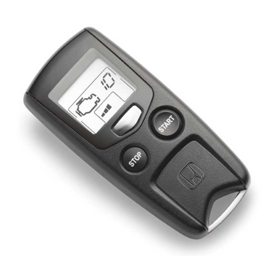
Transmitter
Control unit
Antenna
Key ring
Protective tape
Engine starter label
Fuse label
Accessory User's Information Manual
Quick Start Guide
© 2007 American Honda Motor Co., Inc. - All Rights Reserved.
Accessory
REMOTE ENGINE
STARTER SYSTEM
Remote Engine Starter Attachment Kit
P/N 08E92-SNA-100B
Engine starter harness
Control unit bracket
Relay bracket
3 Black relays (4-pin)
18 Wire ties
AII 38215 (0710)
Application
2008 CIVIC 2-DOOR
Publications No.
AII 38215
Issue Date
OCT 2007
1 of 21
08E92-SVA-1B00-91
Advertisement

Related Manuals for Honda 08E91-E22-100B


Summary of Contents for Honda 08E91-E22-100B
- Page 1 3 Black relays (4-pin) Key ring Protective tape 18 Wire ties Engine starter label Fuse label Accessory User’s Information Manual Quick Start Guide 1 of 21 © 2007 American Honda Motor Co., Inc. - All Rights Reserved. AII 38215 (0710) 08E92-SVA-1B00-91...
- Page 2 RELAY STARTER (5-PIN) Flange nut HARNESS 2 FUSES 40A Clip Green relay (5-pin) CONTROL UNIT 2 FUSES 3A 3 RELAYS Template (4-PIN) 7507010T 2 of 21 AII 38215 (0710) © 2007 American Honda Motor Co., Inc. - All Rights Reserved.
-
Page 3: Tools And Supplies Required
Make sure you have the anti-theft code for the HOOK radio, then write down the radio station presets. Disconnect the negative cable from the battery. LEFT FRONT DOOR SILL TRIM 5311351T 3 of 21 © 2007 American Honda Motor Co., Inc. - All Rights Reserved. AII 38215 (0710) - Page 4 If equipped, remove the driver’s dashboard under cover (turn the knob counterclockwise, and release two clips and pin). DRIVER’S 2 CLIPS DASHBOARD UNDER COVER KNOB 5202112T 4 of 21 AII 38215 (0710) © 2007 American Honda Motor Co., Inc. - All Rights Reserved.
- Page 5 (two retaining tabs). Pull up to remove the column upper cover (two hooks). 5 of 21 © 2007 American Honda Motor Co., Inc. - All Rights Reserved. AII 38215 (0710)
- Page 6 Gently tap the pillar trim at the area marked as “SIDE CURTAIN AIRBAG”. 6 of 21 AII 38215 (0710) © 2007 American Honda Motor Co., Inc. - All Rights Reserved.
- Page 7 PAINT CERAMIC PAINT LEFT FRONT WINDSHIELD TEMPLATE Align the end PILLAR TRIM with the end of the black 5217110T TAPE ceramic paint. 6D01210T 7 of 21 © 2007 American Honda Motor Co., Inc. - All Rights Reserved. AII 38215 (0710)
- Page 8 25. Remove the adhesive backing from the antenna, insert the antenna plate under the roof liner, and attach the antenna to the windshield aligning the template. 26. Remove the template. 8 of 21 AII 38215 (0710) © 2007 American Honda Motor Co., Inc. - All Rights Reserved.
- Page 9 Do not secure the antenna cable to the drain tube. 4 WIRE TIES VEHICLE CLIP DRAIN DASHBOARD TUBE VEHICLE HARNESS ANTENNA CABLE ANTENNA CABLE 5308192T 6D01410T 9 of 21 © 2007 American Honda Motor Co., Inc. - All Rights Reserved. AII 38215 (0710)
- Page 10 SW : 3 Smart Entry SW : 4 Horn or Buzzer Answer Back SW : 5 Trunk Main SW SW : 6 Reserve 10 of 21 AII 38215 (0710) © 2007 American Honda Motor Co., Inc. - All Rights Reserved.
- Page 11 35. Install the four relays to the engine starter 6D01123T harness relay blocks. Be careful to install the CONTROL UNIT relays properly, or a malfunction will result. BRACKET 11 of 21 © 2007 American Honda Motor Co., Inc. - All Rights Reserved. AII 38215 (0710)
- Page 12 ENGINE STARTER HARNESS VEHICLE 7-PIN WIPER 6D01071T CONNECTOR (brown) Pull the connector and SWITCH check that it is locked (Not reconnected.) securely. 6D01091T 12 of 21 AII 38215 (0710) © 2007 American Honda Motor Co., Inc. - All Rights Reserved.
- Page 13 45. Secure the engine starter harness to the vehicle STEERING COLUMN BRACKET SUPPORT BRACKET harness using a wire tie. RELAY BOLT (Reuse.) BRACKET 6D01063T 13 of 21 © 2007 American Honda Motor Co., Inc. - All Rights Reserved. AII 38215 (0710)
- Page 14 48. Use the clip on the engine starter harness to secure the engine starter harness to the fuse box. INSTRUMENT PANEL DRILL BIT (3, 7 mm) DRILL 6D01361T 14 of 21 AII 38215 (0710) © 2007 American Honda Motor Co., Inc. - All Rights Reserved.
- Page 15 4-pin connectors and secure them with a wire tie. Then, secure the vehicle harness with a wire tie. Reconnect the vehicle 42-pin connector. 15 of 21 © 2007 American Honda Motor Co., Inc. - All Rights Reserved. AII 38215 (0710)
- Page 16 14-pin connector to the vehicle 14-pin connector. WHITE VEHICLE 14-PIN FUSE BOX CONNECTOR ENGINE STARTER HARNESS 14-PIN CONNECTOR VEHICLE 14-PIN 6D01152T CONNECTOR (white) 16 of 21 AII 38215 (0710) © 2007 American Honda Motor Co., Inc. - All Rights Reserved.
- Page 17 CHECK, on page 21. 65. Enter the customer’s radio anti-theft code, and reset the radio station presets. 66. Reset the clock. WIRE VEHICLE HARNESS 7401020T 17 of 21 © 2007 American Honda Motor Co., Inc. - All Rights Reserved. AII 38215 (0710)
-
Page 18: Remote Engine Starter Registration
HDS, then click the check button. CHECK BUTTON Select “R/C ENG STARTER.” 752504AS Input the VIN and CHECK BUTTON other required information. 752502AS 18 of 21 AII 38215 (0710) © 2007 American Honda Motor Co., Inc. - All Rights Reserved. - Page 19 Input the PCM code. Select CHECK BUTTON “REGISTER REMOTE CONTROL ENGINE STARTER UNIT.” 752506AS CHECK BUTTON 752509AS 19 of 21 © 2007 American Honda Motor Co., Inc. - All Rights Reserved. AII 38215 (0710)
-
Page 20: Check Button
"Check that the engine can be started by the Transmitter" CHECK BUTTON 752511AS 13. Perform the function check on page 21, then disconnect the HDS. 20 of 21 AII 38215 (0710) © 2007 American Honda Motor Co., Inc. - All Rights Reserved. -
Page 21: Function Check
Check the operation of the transmitter when the vehicle is 100 m to 150 m (325 to 490 ft.) away and when the vehicle is in direct sight. 21 of 21 © 2007 American Honda Motor Co., Inc. - All Rights Reserved. AII 38215 (0710)