Honda 08E91-E22-100B Installation Instructions Manual
2006 civic 2-door; 2007 civic 2-door; 2008 civic 2-door
Hide thumbs
Also See for 08E91-E22-100B:
- Installation instructions manual (21 pages) ,
- Installation instructions manual (21 pages) ,
- Installation instructions manual (20 pages)
Table of Contents
Advertisement
Quick Links
www.collegehillshonda.com
INSTRUCTIONS
PARTS LIST
Remote Engine Starter Unit Kit
P/N 08E91-E22-100B
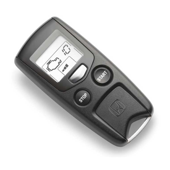
Transmitter
Control unit
Antenna
Key ring
Protective tape
Engine starter label
Fuse label
Accessory User's Information Manual
Quick Start Guide
© 2008 American Honda Motor Co., Inc. - All Rights Reserved.
Accessory
REMOTE ENGINE
STARTER SYSTEM
Remote Engine Starter Attachment Kit
P/N 08E92-SNA-100B
Engine starter harness
Control unit bracket
Relay bracket
3 Black relays (4-pin)
18 Wire ties
AII 38215-38958 (0802)
Application
2006-2008 CIVIC 2-DOOR
(A/T ONLY)
Publications No.
AII 38215-38958
Issue Date
FEB 2008
1 of 22
08E92-SVA-1B00-91
Advertisement
Table of Contents

Related Manuals for Honda 08E91-E22-100B


Summary of Contents for Honda 08E91-E22-100B
- Page 1 INSTALLATION INSTRUCTIONS PARTS LIST Remote Engine Starter Unit Kit P/N 08E91-E22-100B Transmitter Control unit Antenna Key ring Protective tape Engine starter label Fuse label Accessory User’s Information Manual Quick Start Guide © 2008 American Honda Motor Co., Inc. - All Rights Reserved.
- Page 2 7 Foam cushion tapes Flange nut Clip Green relay (5-pin) Template Illustration of the Engine Starter System Installed on the Vehicle ANTENNA RELAY (5-PIN) 2 FUSES 40 A 2 FUSES 3 A 3 RELAYS (4-PIN) 2 of 22 TOOLS AND SUPPLIES REQUIRED Phillips screwdriver Long blade flat-tip screwdriver Small flat-tip screwdriver...
- Page 3 Setting the Control Unit Get the control unit. Using a small flat-tip screwdriver, adjust the switches on the control unit to the locations shown. Using a isopropyl alcohol on a shop towel, clean the area where the protective tape will attach. Attach the protective tape to the control unit over the switches.
- Page 4 Using the key, unlock the opener. Remove the left front door sill trim (two retaining tabs, five clips, and three hooks). 3 HOOKS FRONT LEFT FRONT DOOR SILL TRIM Pull away the weatherstrip, and remove the left kick panel (two clips). WEATHERSTRIP 2 CLIPS 4 of 22...
- Page 5 10. Lower the tilt lever, and pull the steering wheel toward you. Insert a long blade flat-tip screwdriver along the guide of the column lower cover, and pry the retaining tab of the column upper cover. 2 RETAINING TABS Push. COLUMN UPPER COVER...
- Page 6 13. If equipped, use a small flat-tip screwdriver to remove the left and right lens from the map light console (four retaining tabs for each lens). Remove the two bolts, and then release the map light console. BOLT LENS 14. Remove the sunvisor holders. Using a small flat- tip screwdriver, push the hook, and turn the holder 90°, then pull it out.
- Page 7 19. Pull away the weatherstrip from the left front pillar trim. Remove the left front pillar trim (two clips). LEFT FRONT 2 CLIPS PILLAR TRIM WEATHERSTRIP 20. Remove the clip from the left front pillar trim, and install a new clip on the left front pillar trim. NEW CLIP LEFT FRONT PILLAR TRIM...
- Page 8 23. Using two pairs of needle-nose pliers, bend the antenna plate according to the illustration and measurement shown. ANTENNA 15 mm (0.6 in.) 8 mm (0.3 in.) SCALE NEEDLE-NOSE PLIERS PLATE 8 of 22 24. Measure the antenna cable as shown. Attach the three foam cushion tapes to the antenna cable in the measurement shown.
- Page 9 28. Route the antenna cable under the roof liner towards the driver’s side of vehicle, and down along the vehicle harness. Be careful not to crease the roof liner. ROOF LINER VEHICLE HARNESS ANTENNA CABLE 29. Continue routing the antenna cable between the front pillar and the dashboard.
- Page 10 32. Secure the antenna cable to the vehicle harness with a wire tie. Secure the wire tie between the vehicle harness branching points. WIRE TIE VEHICLE HARNESS BRANCHING POINT 10 of 22 Installing the Control Unit Bracket 33. Locate the small square hole next to the small round hole in the dashboard support bracket.
- Page 11 Routing the Engine Starter Harness 34. Attach the 3A fuse labels to the engine starter harness fuse case, and the 40A fuse labels to the fuse block. LAYOUT OF RELAYS WHEN VIEWED FROM FRONT 4-PIN RELAY (black) RELAY 5-PIN BLOCK RELAY (green) 40A FUSE...
- Page 12 37. Unplug the brown vehicle 7-pin connector, and plug the brown engine starter harness 7-pin connector into the brown vehicle 7-pin connector. NOTICE Make sure that the engine starter harness 7-pin connector (brown) is connected to the vehicle connector and it is locked securely. A loosely connected connector can cause engine stall during driving.
- Page 13 40. Wrap the vehicle 7-pin connector with one foam cushion tape, then place the vehicle 7-pin connector into the gap of the column. VEHICLE 7-PIN CONNECTOR (brown) (Squeeze into this area.) FOAM CUSHION TAPE VEHICLE 7-PIN VEHICLE CONNECTOR BRACKET 41. Secure the engine starter harness to the vehicle harness with four wire ties in the areas shown.
- Page 14 46. With driver's dashboard under cover: Measure the indicated dimension on the instrument panel and mark with a felt-tip pen and a center punch. INSTRUMENT PANEL View from below 12 mm (0.5 in.) FELT-TIP PEN FRONT 6 mm (0.2 in.) •...
- Page 15 49. Disconnect the vehicle 42-pin, 4-pin, and 2-pin connectors. VEHICLE 4-PIN CONNECTOR VEHICLE 42-PIN CONNECTOR FUSE BOX FUSE BOX VEHICLE 4-PIN CONNECTOR LOCK VEHICLE 42-PIN CONNECTOR © 2008 American Honda Motor Co., Inc. - All Rights Reserved. 50. Plug the engine starter harness 4-pin and 2-pin connectors into the fuse box.
- Page 16 52. Behind the fuse box, unplug the blue vehicle 23- pin connector from the inside of the front lower pillar, and plug the blue engine starter harness 23- pin connectors into the blue vehicle 23-pin connector. If the vehicle 23-pin connector is difficult to disconnect, perform the work after first disconnecting the connector on the upper side.
- Page 17 Installing the Control Unit 56. Connect the antenna cable terminal and the engine starter harness 18-pin connector to the control unit. ANTENNA CABLE TERMINAL (Connect first.) CONTROL UNIT ENGINE STARTER BRACKET HARNESS 18-PIN CONNECTOR 57. Install the control unit on the control unit bracket. 58.
- Page 18 REMOTE ENGINE STARTER REGISTRATION Acquire the PCM code from ISIS. Connect the HDS tester to the OBD II data link connector, then turn the ignition switch to the ON (II) position. Start the HDS, and click the car icon. Input the VIN and other required information into the HDS, then click the check button.
- Page 19 A REMARKS message will display. Click the check button. “REMARKS” message Select REGISTER REMOTE CONTROL ENGINE STARTER UNIT, then click the check button. Select “REGISTER REMOTE CONTROL ENGINE STARTER UNIT.” © 2008 American Honda Motor Co., Inc. - All Rights Reserved. The following message will display: Obtain PCM- code (IMMOBILIZER PCM CODE) from iN.
- Page 20 11. The following message will display: The registration of the Remote Control Engine Starter Unit has been completed. Click the check button. "Registration" message 12. The following message will display: Check that the engine can be started by the Transmitter. Click the check button.
- Page 21 FUNCTION CHECK Operating Conditions • The hood is closed. • The shift lever is in Park. • The key is not in the ignition switch. • All doors and trunk are closed and locked. Inspection Within 1 second, press the command button and then the start button on the transmitter. The engine should start if all operating conditions are met.
- Page 22 How to Program an Additonal Transmitter Connect the HDS to the data link connector. Start the HDS and click on the car icon. Input the vehicle's VIN and other required information. Select Honda Systems. Select R/C Engine Starter. Select REGISTER NEW TRANSMITTER. When "Ready to program the new transmitter"...