Advertisement
Quick Links
INSTALLATION
INSTRUCTIONS
PARTS LIST
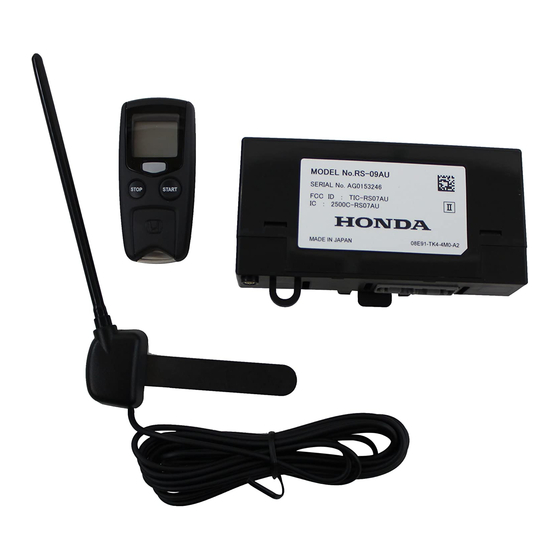
Remote Engine Starter Unit Kit
P/N 08E91-E22-100A
Transmitter
Control unit
Antenna
Key ring
Protective tape
Caution label
Fuse labels
© 2007 American Honda Motor Co., Inc. – All Rights Reserved.
Accessory
REMOTE CONTROL
ENGINE STARTER
Accessory User's Information Manual
Quick start guide
Remote Control Engine Starter Attachment Kit
P/N 08E92-TA0-100
Engine starter harness
Control unit bracket
Template
3
Flange nut
AII 35365 (0708)
Application
2008 ACCORD
4-DOOR
U
Relays
Publications No.
AII 35365
Issue Date
AUG 2007
1 of 24
08E92-TA0-1000-91
Advertisement

Related Manuals for Honda 08E91-E22-100A


Summary of Contents for Honda 08E91-E22-100A
- Page 1 Remote Control Engine Starter Attachment Kit P/N 08E92-TA0-100 Engine starter harness Antenna Control unit bracket Template Key ring Protective tape Relays Caution label Flange nut Fuse labels 1 of 24 © 2007 American Honda Motor Co., Inc. – All Rights Reserved. AII 35365 (0708) 08E92-TA0-1000-91...
-
Page 2: Installation
Combination wrench Isopropyl alcohol Shop towel Tape measure Clip remover Scissors Small rubber mallet Honda Diagnostic System (HDS) Masking tape Needle nose pliers 2 of 24 AII 35365 (0708) © 2007 American Honda Motor Co., Inc. – All Rights Reserved. - Page 3 Raise the front portion of the left front door sill trim (four clips and retaining tab). FRONT 4 CLIPS DRIVER’S DASHBOARD UNDER COVER 6D18040Y RETAINING LEFT FRONT DOOR SILL TRIM 760501AE 3 of 24 © 2007 American Honda Motor Co., Inc. – All Rights Reserved. AII 35365 (0708)
- Page 4 11. Remove the lower steering column cover (three screws). The upper screws are self-tapping screws. 3 HOOKS WEATHERSTRIP LOWER 6D1805BY STEERING COLUMN COVER SELF-TAPPING SCREWS SCREW 7111090Y 4 of 24 AII 35365 (0708) © 2007 American Honda Motor Co., Inc. – All Rights Reserved.
- Page 5 Push and ROOF hold tab. CONSOLE Rotate towards SUNGLASS the door. HOLDER 4 SCREWS Open. 7215020Y LEFT Push upward. SUNVISOR (Turn rearward.) 761804AB 5 of 24 © 2007 American Honda Motor Co., Inc. – All Rights Reserved. AII 35365 (0708)
- Page 6 Remove the left front A-pillar trim (two clips). HANDS- LEFT FRONT FREELINK 2 CLIPS A-PILLAR TRIM CONTROL UNIT BOLT VEHICLE BOLT 28-PIN 732903BY CONNECTOR WEATHERSTRIP 6D18070Y 6 of 24 AII 35365 (0708) © 2007 American Honda Motor Co., Inc. – All Rights Reserved.
- Page 7 SW:2 Trunk or Tailgate SW:3 Smart Entry SW:4 Horn or Buzzer Answerback SW:5 Trunk Main SW ENGINE STARTER SW:6 Reserve HARNESS RELAY BLOCK 6D1802BY 7 of 24 © 2007 American Honda Motor Co., Inc. – All Rights Reserved. AII 35365 (0708)
- Page 8 A loose connector can cause engine to stall. VEHICLE BRACKET BRAKE PEDAL BRACKET 6D1810AY 12-PIN/8-PIN/5-PIN CONNECTOR 8 of 24 AII 35365 (0708) © 2007 American Honda Motor Co., Inc. – All Rights Reserved.
- Page 9 12-pin connector into the turn signal switch. HARNESS 12-PIN CONNECTORS TURN SIGNAL SWITCH 12-PIN 8-PIN CONNECTOR CONNECTORS WIRE TIES 6D1816BY BODY SWITCH ENGINE STARTER HARNESS 6D18141Y 9 of 24 © 2007 American Honda Motor Co., Inc. – All Rights Reserved. AII 35365 (0708)
- Page 10 VEHICLE 20-PIN CONNECTOR 36. Secure the engine starter harness to the vehicle 6D1818AY harness with two long wire ties at the locations shown. 10 of 24 AII 35365 (0708) © 2007 American Honda Motor Co., Inc. – All Rights Reserved.
- Page 11 STARTER 6D1820AY Lock connector HARNESS Unlock connector 39. Loosely attach the engine starter harness to the 6D1823DY vehicle harness with one wire tie. 11 of 24 © 2007 American Honda Motor Co., Inc. – All Rights Reserved. AII 35365 (0708)
- Page 12 FUSE BOX 20-PIN CONNECTOR DUMMY CONNECTOR ENGINE STARTER OTHER ACCESSORY HARNESS CONNECTOR ENGINE STARTER HARNESS 6D1825AY 20-PIN CONNECTOR 12-PIN CONNECTOR ENGINE STARTER HARNESS 6D1822BY 12 of 24 AII 35365 (0708) © 2007 American Honda Motor Co., Inc. – All Rights Reserved.
- Page 13 HARNESS VEHICLE BOLT (Discard.) VEHICLE HARNESS GROUND ENGINE STARTER BOLT HARNESS GROUND TERMINAL WIRE TIES HOOD (Attach loosely.) OPENER VEHICLE HARNESS 6D18290Y 6D18270Y 13 of 24 © 2007 American Honda Motor Co., Inc. – All Rights Reserved. AII 35365 (0708)
- Page 14 49. Determine the appropriate template for the vehicle you are working on. Using scissors, cut out the Cut out. appropriate template. TEMPLATE Without Shaded Glass Cut out. TEMPLATE 721506DY 721505DY 14 of 24 AII 35365 (0708) © 2007 American Honda Motor Co., Inc. – All Rights Reserved.
- Page 15 52. Using scissors, cut one foam cushion in half. Wrap SCALE the two halves of the foam cushion around the 721509BY antenna cable at the measurements shown. 15 of 24 © 2007 American Honda Motor Co., Inc. – All Rights Reserved. AII 35365 (0708)
- Page 16 OF MIRROR BASE 6D1838BY With shaded glass, without Day/Night Mirror BLACK CERAMIC TAPE TEMPLATE CENTER FRONT WINDOW BLACK CERAMIC OF 6D1837BY MIRROR BASE 16 of 24 AII 35365 (0708) © 2007 American Honda Motor Co., Inc. – All Rights Reserved.
- Page 17 57. Gently pull down the headliner, and tuck the antenna ANTENNA FRONT PILLAR cable under it. CABLE TRIM OPENING HEADLINER VEHICLE HARNESS ANTENNA CABLE 721511AY 6D18400Y 17 of 24 © 2007 American Honda Motor Co., Inc. – All Rights Reserved. AII 35365 (0708)
- Page 18 CONTROL UNIT BRACKET WIRE VEHICLE HARNESS 6D1844AY CONTROL UNIT 62. Secure the antenna cable to the vehicle harness with two wire ties. 6D18461Y 18 of 24 AII 35365 (0708) © 2007 American Honda Motor Co., Inc. – All Rights Reserved.
- Page 19 68. Plug the antenna terminal into the control unit. ANTENNA TERMINAL VEHICLE CONNECTOR CONTROL UNIT 6D18480Y URETHANE TAPE 732901CY 19 of 24 © 2007 American Honda Motor Co., Inc. – All Rights Reserved. AII 35365 (0708)
- Page 20 ENGINE STARTER VEHICLE HARNESS 6D18620Y HARNESS 73. Secure the antenna cable to the engine starter harness with two additional wire ties. 20 of 24 AII 35365 (0708) © 2007 American Honda Motor Co., Inc. – All Rights Reserved.
-
Page 21: Remote Engine Starter Registration
HDS, then click the check on button. Select CHECK BUTTON “R/C ENG STARTER.” 752504AS Input the VIN and other required information. CHECK BUTTON 752502AS 21 of 24 © 2007 American Honda Motor Co., Inc. – All Rights Reserved. AII 35365 (0708) - Page 22 The date of the HDS tester should also be the same. Input the PCM code. Select “REGISTER REMOTE CONTROL CHECK BUTTON ENGINE STARTER UNIT.” 752506AS CHECK BUTTON 752509AS 22 of 24 AII 35365 (0708) © 2007 American Honda Motor Co., Inc. – All Rights Reserved.
- Page 23 “Check that the engine can be started by the Transmitter” CHECK BUTTON 752511AS 13. Perform the function test on page 24, then disconnect the HDS. 23 of 24 © 2007 American Honda Motor Co., Inc. – All Rights Reserved. AII 35365 (0708)
-
Page 24: Function Check
Check the operation of the transmitter when the vehicle is 100 m to 150 m (325 ft. to 490 ft.) away and when the vehicle is in direct sight. 24 of 24 AII 35365 (0708) © 2007 American Honda Motor Co., Inc. – All Rights Reserved.