Advertisement
Table of Contents
- 1 Parts List
- 2 Tools and Supplies Required
- 3 Installation
- 4 Removing the Vehicle Parts
- 5 Installing the Antenna
- 6 Routing the Engine Starter Harness
- 7 Installing the Control Unit
- 8 Remote Engine Starter Registration
- 9 Check Button
- 10 Operating Conditions
- 11 Does the Engine Start?
- 12 Does the Engine Stop?
- 13 Does the Engine Stop after each of These Tests?
- Download this manual
See also:
Instruction and Installation Manual
INSTRUCTIONS
PARTS LIST
Remote Control Engine Starter Kit
P/N 08E91-E54-100
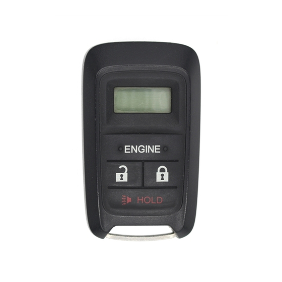
Transmitter
Control unit
Antenna
ID label
Remote Control Engine Starter Attachment Kit
P/N 08E92-T0A-100B
Control unit bracket
Engine starter harness
© 2013 American Honda Motor Co., Inc. – All Rights Reserved.
Accessory
REMOTE CONTROL
ENGINE STARTER
3
20 Cable ties
Long Cable tie
6
Clip
Caution label
Fuse label
Accessory User's Information Manual
AII 50024-50373 (1308)
Application
2014 CR-V
Relays
Urethane tapes
Publications No.
AII 50024-50373
Issue Date
AUG 2013
1 of 25
08E92-T0A-1B00-90
Advertisement
Table of Contents

Related Manuals for Honda 08E91-E54-100


Summary of Contents for Honda 08E91-E54-100
- Page 1 Remote Control Engine Starter Attachment Kit Caution label P/N 08E92-T0A-100B Control unit bracket Fuse label Engine starter harness Accessory User’s Information Manual 1 of 25 © 2013 American Honda Motor Co., Inc. – All Rights Reserved. AII 50024-50373 (1308) 08E92-T0A-1B00-90...
- Page 2 Illustration of the Remote Control Engine Starter Installed on the Vehicle ANTENNA CONTROL UNIT Clean with isopropyl 40A FUSE alcohol. QBD0601AE 3 RELAYS ENGINE 3A FUSE STARTER QC50901AB HARNESS 2 of 25 AII 50024-50373 (1308) © 2013 American Honda Motor Co., Inc. – All Rights Reserved.
- Page 3 4 RETAINING TABS 4 RETAINING Q0N2012AG TABS VEHICLE CLIP PANEL DRIVER’S A-PILLAR TRIM DRIVER’S DOOR SEAL (Pull away.) 2 CLIPS DRIVER’S A-PILLAR Q0N2014AG 3 of 25 © 2013 American Honda Motor Co., Inc. – All Rights Reserved. AII 50024-50373 (1308)
- Page 4 NOTE: The upper clip will stay in the body. DRIVER’S NEW CLIP UPPER CLIP A-PILLAR TRIM DRIVER’S (Remove.) A-PILLAR TRIM (inside) DRIVER’S A-PILLAR TRIM Q0N2018AG Q0N2016AG 4 of 25 AII 50024-50373 (1308) © 2013 American Honda Motor Co., Inc. – All Rights Reserved.
- Page 5 2 CLIPS DRIVER’S VEHICLE AIR OUTLET CONNECTORS RETAINING SELF-TAPPING SCREW CLIP Q0N2020BG DRIVER’S DASH- BOARD LOWER COVER 8 CLIPS QAN2325AD 5 of 25 © 2013 American Honda Motor Co., Inc. – All Rights Reserved. AII 50024-50373 (1308)
- Page 6 UPPER COLUMN COVER TAPE LOCK UPPER COLUMN COVER PLASTIC TRIM Q0N2026AG TOOL Q0N2024BG 17. Using a plastic trim tool, release the lock as shown. 6 of 25 AII 50024-50373 (1308) © 2013 American Honda Motor Co., Inc. – All Rights Reserved.
- Page 7 DRIVER’S DOOR OPENING SEAL (Pull away.) 2 CLIPS LOWER COLUMN COVER SELF-TAPPING DRIVER’S KICK SCREW Q0N2028AG Q0N2030AG PANEL 7 of 25 © 2013 American Honda Motor Co., Inc. – All Rights Reserved. AII 50024-50373 (1308)
- Page 8 (0.4 in.) ANTENNA CABLE ANTENNA QB51401CH URETHANE TAPE QC50903AB 26. Measure and wrap another piece of urethane tape around the antenna cable as shown. 8 of 25 AII 50024-50373 (1308) © 2013 American Honda Motor Co., Inc. – All Rights Reserved.
- Page 9 DRIVER’S A-PILLAR QC50905AB ADHESIVE 30. Secure the antenna cable to the vehicle harness MASKING TAPE BACKING using six cable ties. (Remove.) (Remove.) QB51405CH 9 of 25 © 2013 American Honda Motor Co., Inc. – All Rights Reserved. AII 50024-50373 (1308)
- Page 10 35. Route the two 28-pin starter harness connectors upward as shown. ENGINE STARTER STEERING HARNESS HANGER BEAM 28-PIN CONNECTOR QC50907AB ENGINE STARTER HARNESS 10 of 25 AII 50024-50373 (1308) © 2013 American Honda Motor Co., Inc. – All Rights Reserved.
- Page 11 28-PIN CONNECTOR VEHICLE TOP VIEW 28-PIN CONNECTOR Q0N1805BG 39. Plug the other vehicle 28-pin connector into the engine starter harness 28-pin connector. 11 of 25 © 2013 American Honda Motor Co., Inc. – All Rights Reserved. AII 50024-50373 (1308)
- Page 12 NOTE: Make sure that the engine starter harness 5- pin connector is securely connected to the fuse box. A loose connection can cause the engine to stall. QC50910AB 12 of 25 AII 50024-50373 (1308) © 2013 American Honda Motor Co., Inc. – All Rights Reserved.
- Page 13 FOG LIGHTS QC50912AB ENGINE STARTER 4-PIN HARNESS 4-PIN QC50911AB CONNECTOR CONNECTOR 48. Plug the remaining 4-pin connector into the fuse box. 13 of 25 © 2013 American Honda Motor Co., Inc. – All Rights Reserved. AII 50024-50373 (1308)
- Page 14 24-PIN CONNECTOR QC50913AB ENGINE STARTER HARNESS 24-PIN CONNECTOR FUSE BOX VEHICLE 24-PIN CONNECTOR ENGINE STARTER HARNESS 24-PIN CONNECTOR QC50914AB 14 of 25 AII 50024-50373 (1308) © 2013 American Honda Motor Co., Inc. – All Rights Reserved.
- Page 15 53. Secure the engine starter harness to the hole in the left knee bolster using the clip on the engine starter harness as shown. 15 of 25 © 2013 American Honda Motor Co., Inc. – All Rights Reserved. AII 50024-50373 (1308)
- Page 16 62. Plug the remaining 10-pin connector into the wiper switch. VEHICLE HARNESS 7-PIN CONNECTORS CABLE ENGINE Q090211BK STARTER HARNESS 16 of 25 AII 50024-50373 (1308) © 2013 American Honda Motor Co., Inc. – All Rights Reserved.
- Page 17 HARNESS 12-PIN CONNECTOR VEHICLE 12-PIN CONNECTOR ENGINE STARTER HARNESS 12-PIN CONNECTOR QA20704BG 65. Plug the remaining 12-pin connector into the combination light switch. 17 of 25 © 2013 American Honda Motor Co., Inc. – All Rights Reserved. AII 50024-50373 (1308)
- Page 18 69. Loosely secure the antenna cable to the dashboard with the cable tie installed in step 54. Do not strain the right connector harness. Q0N2010BG 18 of 25 AII 50024-50373 (1308) © 2013 American Honda Motor Co., Inc. – All Rights Reserved.
- Page 19 BLOCK CONTROL HOLE UNIT ANTENNA CABLE CONNECTOR ENGINE STARTER HARNESS CLIP Q0N2308BG ENGINE STARTER HARNESS 28-PIN CONNECTOR QC50917AB 19 of 25 © 2013 American Honda Motor Co., Inc. – All Rights Reserved. AII 50024-50373 (1308)
- Page 20 69. ANTENNA CABLE (Bundle up the excess.) DASHBOARD CABLE TIE QC61402AY 20 of 25 AII 50024-50373 (1308) © 2013 American Honda Motor Co., Inc. – All Rights Reserved.
- Page 21 Start the HDS, and click the car icon. ADHESIVE BACKING (Remove.) Q0N2011AG 83. Remove the adhesive backing from the caution label, and attach the caution label to the hood. 21 of 25 © 2013 American Honda Motor Co., Inc. – All Rights Reserved. AII 50024-50373 (1308)
- Page 22 STARTER UNIT, then click the check button. Select Select “Honda Systems.” “REGISTER REMOTE CONTROL ENGINE STARTER UNIT.” CHECK BUTTON CHECK BUTTON QB32103AH QB32105BH 22 of 25 AII 50024-50373 (1308) © 2013 American Honda Motor Co., Inc. – All Rights Reserved.
- Page 23 CHECK BUTTON QB32109CH 12. Perform the Check the operation of the Remote Control Engine Starter, then disconnect the HDS/ MVCI. CHECK BUTTON QB32107BH 23 of 25 © 2013 American Honda Motor Co., Inc. – All Rights Reserved. AII 50024-50373 (1308)
- Page 24 • Check the engine starter harness connections. • Connect the HDS/MVCI and check for an indicated failure. (Refer to the Service Manual for troubleshooting.) 24 of 25 AII 50024-50373 (1308) © 2013 American Honda Motor Co., Inc. – All Rights Reserved.
- Page 25 Make sure the vehicle key can start the engine, and that the wipers and the headlights operate normally. 25 of 25 © 2013 American Honda Motor Co., Inc. – All Rights Reserved. AII 50024-50373 (1308)