Honda 08E91-E22-100B Installation Instructions Manual
Honda 2011 civic 4-door
Hide thumbs
Also See for 08E91-E22-100B:
- Installation instructions manual (23 pages) ,
- Installation instructions manual (21 pages) ,
- Installation instructions manual (21 pages)
Advertisement
Quick Links
INSTALLATION
INSTRUCTIONS
PARTS LIST
Remote Engine Starter Unit Kit
P/N 08E91-E22-100B
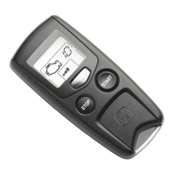
Transmitter
Control unit
Antenna
Key ring
Protective tape
Engine starter label
© 2010 American Honda Motor Co., Inc. – All Rights Reserved.
Accessory
REMOTE ENGINE STARTER
SYSTEM
AII 44399 (1008)
Application
2011 CIVIC
4-DOOR
Fuse label
Accessory User's Information Manual
Quick Start Guide
Remote Engine Starter Attachment Kit
P/N 08E92-SNA-100B
Engine starter harness
Control unit bracket
Relay bracket
Publications No.
AII 44399
Issue Date
AUG 2010
1 of 21
08E92-SNA-1B01-91
Advertisement

Related Manuals for Honda 08E91-E22-100B


Summary of Contents for Honda 08E91-E22-100B
- Page 1 Remote Engine Starter Attachment Kit P/N 08E92-SNA-100B Engine starter harness Key ring Control unit bracket Protective tape Relay bracket Engine starter label 1 of 21 © 2010 American Honda Motor Co., Inc. – All Rights Reserved. AII 44399 (1008) 08E92-SNA-1B01-91...
-
Page 2: Tools And Supplies Required
Scissors 2 Pairs of needle nose pliers Rubber mallet HDS (Honda Diagnostic System) Clip Masking tape Safety goggles Scale Green relay (5-pin) Template 2 of 21 AII 44399 (1008) © 2010 American Honda Motor Co., Inc. – All Rights Reserved. -
Page 3: Installation
SW:2 Trunk or Tailgate ----------------------> OFF SW:3 Smart Entry -----------------------------> OFF SW:4 Horn or Buzzer Answerback ------> OFF SW:5 Trunk Main SW -------------------------> OFF SW:6 Reserve ----------------------------------> ON 3 of 21 © 2010 American Honda Motor Co., Inc. – All Rights Reserved. AII 44399 (1008) - Page 4 Using the key, unlock the opener. Pull away the weatherstrip, and remove the left kick panel (two clips). WEATHERSTRIP 2 CLIPS LEFT KICK PANEL 872604AT 4 of 21 AII 44399 (1008) © 2010 American Honda Motor Co., Inc. – All Rights Reserved.
- Page 5 (two retaining tabs). Pull up to remove the column upper cover (two hooks). DRIVER’S DASHBOARD LOWER COVER 8 CLIPS 872606AT 5 of 21 © 2010 American Honda Motor Co., Inc. – All Rights Reserved. AII 44399 (1008)
- Page 6 SCREWS 872611AT LENS 16. Remove the left sunvisor (two T25 Torx screws, and 872609AT 4 RETAINING unplug the vehicle connectors, if equipped). TABS 6 of 21 AII 44399 (1008) © 2010 American Honda Motor Co., Inc. – All Rights Reserved.
- Page 7 A-pillar trim at the position shown to release the clip. Gently tap the pillar trim just below the “SIDE CURTAIN AIRBAG” mark. CLIP Discard. A-PILLAR TRIM 872614AT 7 of 21 © 2010 American Honda Motor Co., Inc. – All Rights Reserved. AII 44399 (1008)
- Page 8 EDGE OF BLACK PLATE BLACK CERAMIC CERAMIC PAINT PAINT Align with the edge of TEMPLATE the black 872617AT WINDSHIELD ceramic paint. MASKING TAPE 872616AT 8 of 21 AII 44399 (1008) © 2010 American Honda Motor Co., Inc. – All Rights Reserved.
- Page 9 26. Remove the backing from the antenna, insert the antenna plate under the headliner, and attach the antenna to the windshield in alignment with the template. 27. Remove the template. 9 of 21 © 2010 American Honda Motor Co., Inc. – All Rights Reserved. AII 44399 (1008)
- Page 10 Do not secure the antenna cable to the drain tube. DRAIN TUBE 4 WIRE TIES VEHICLE CLIP VEHICLE HARNESS ANTENNA CABLE 872623AT 10 of 21 AII 44399 (1008) © 2010 American Honda Motor Co., Inc. – All Rights Reserved.
- Page 11 35. Install the four relays to the engine starter harness 872626AT relay blocks. Be careful to install the relays properly, or a malfunction will result. 11 of 21 © 2010 American Honda Motor Co., Inc. – All Rights Reserved. AII 44399 (1008)
- Page 12 HARNESS 7-PIN CONNECTOR (Brown) WIPER SWITCH 872631AT VEHICLE 7-PIN CONNECTOR Pull the connector and check (Brown) that it is locked securely. (Not reconnected.) 872629AT 12 of 21 AII 44399 (1008) © 2010 American Honda Motor Co., Inc. – All Rights Reserved.
- Page 13 45. Secure the engine starter harness to the vehicle STEERING harness using one wire tie. COLUMN STEERING SUPPORT COLUMN BRACKET SUPPORT RELAY BRACKET BOLT BRACKET Reuse. 872633AT 13 of 21 © 2010 American Honda Motor Co., Inc. – All Rights Reserved. AII 44399 (1008)
- Page 14 FUSE BOX FRONT VIEW DRILL BIT (3 mm, 7 mm) VEHICLE 2-PIN CONNECTOR VEHICLE 4-PIN CONNECTOR LOCK DRILL VEHICLE 42-PIN CONNECTOR 872637AT 872639AT 14 of 21 AII 44399 (1008) © 2010 American Honda Motor Co., Inc. – All Rights Reserved.
- Page 15 Then, secure the vehicle harness with one wire tie. Reconnect the vehicle 42-pin connector. ENGINE STARTER HARNESS 14-PIN CONNECTOR VEHICLE 14-PIN CONNECTOR (White) 872642AT 15 of 21 © 2010 American Honda Motor Co., Inc. – All Rights Reserved. AII 44399 (1008)
- Page 16 61. Remove the backing from the engine starter label. CONTROL Attach the engine starter label to the back of the UNIT hood. CONTROL UNIT ENGINE STARTER BRACKET HARNESS 18-PIN CONNECTOR 872644AT 16 of 21 AII 44399 (1008) © 2010 American Honda Motor Co., Inc. – All Rights Reserved.
-
Page 17: Remote Engine Starter Registration
Input the VIN and other required information into the HDS, then click the check button. Input the VIN and CHECK BUTTON other required information. 17 of 21 © 2010 American Honda Motor Co., Inc. – All Rights Reserved. AII 44399 (1008) - Page 18 Select REGISTER REMOTE CONTROL ENGINE STARTER UNIT, then click the check button. Select CHECK BUTTON “R/C ENG STARTER.” Select CHECK BUTTON “REGISTER REMOTE CONTROL ENGINE STARTER UNIT.” 18 of 21 AII 44399 (1008) © 2010 American Honda Motor Co., Inc. – All Rights Reserved.
- Page 19 The date of the HDS tester should also be the same. Input the PCM code. CHECK BUTTON 13. Perform the function test on the next page, then CHECK BUTTON disconnect the HDS. 19 of 21 © 2010 American Honda Motor Co., Inc. – All Rights Reserved. AII 44399 (1008)
-
Page 20: Function Check
Check the operation of the transmitter when the vehicle is 100 m to 150 m (325 to 490 ft.) away, and when the vehicle is in direct sight. 20 of 21 AII 44399 (1008) © 2010 American Honda Motor Co., Inc. – All Rights Reserved. - Page 21 Press and release the Stop button. 10. Perform the function check on both transmitters. NOTE: Only two remotes can be stored in the system’s memory. 21 of 21 © 2010 American Honda Motor Co., Inc. – All Rights Reserved. AII 44399 (1008)