NorthStar 951X Installation Manual
Gps chart navigators
Hide thumbs
Also See for 951X:
- Operator's manual (206 pages) ,
- Installation manual (80 pages) ,
- Addendum operator's manual (12 pages)
Table of Contents
Troubleshooting

Related Manuals for NorthStar 951X


Summary of Contents for NorthStar 951X
- Page 1 951X/XD 952X/XD GPS C HART AVIGATORS NSTALLATION ANUAL Revision B Part Number GM1505C Northstar Technologies www.northstarcmc.com 30 Sudbury Road Service: 978/897-0770 Acton, Massachusetts 01720 Sales: 978/897-6600...
- Page 3 Northstar’s facilities in Acton, Massachusetts. Performance of warranty work elsewhere will not be authorized, and Northstar will not pay for any charges for such work. Northstar will not be responsible for payment of any charges imposed by a Northstar dealer or other party for services requested by and/or performed for a unit’s owner in connection...
-
Page 5: Table Of Contents
Contents SECTION ONE - Introduction..........1 Welcome . - Page 6 Page ii 951/952 INSTALLATION MANUAL Revision B...
- Page 7 Figures Figure 1: 951/952 dimensions (side) ............9 Figure 2: 951/952 dimensions (front) .
- Page 8 Page iv 951/952 INSTALLATION MANUAL Revision B...
- Page 9 Table 7: Connecting to an external Northstar beacon receiver ....... .
- Page 10 Page vi 951/952 INSTALLATION MANUAL Revision B...
-
Page 11: Section One - Introduction
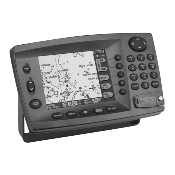
951 and 952 GPS chart navigators. The 952 features a color display, but is otherwise identical to the 951, except where noted. The 951X and 952X are both differential-ready so you can interface them to an external differential receiver. The 951XD and 952XD have built-in dif- ferential receivers. -
Page 12: Servicing The Unit
Servicing the unit Repair of the unit is performed only at the Northstar factory. Service includes a complete hardware and software check-out. NOTE: Field repairs are not authorized and will void the warranty! For a system under warranty, shipping charges to the factory are the only cost for factory repair. -
Page 13: Returning A Unit For Service
Northstar will repair or replace, free of serial number so charge, any part found to be defective due to faulty materials or work- they can give you an manship if the system has been properly installed and hasn’t been... - Page 14 SECTION ONE - Introduction Page 4 951/952 INSTALLATION MANUAL Revision B...
-
Page 15: Section Two - Installing The Unit
The rest of this chapter describes how to wire the unit, install the antenna, and trouble- shoot. Proper installation of the Northstar 951/952 is of utmost impor- tance to accurately receive and effectively use GPS signals under a wide variety of weather conditions. -
Page 16: System Overview
2. Unpack the carton, and compare its contents with those on the pack- ing list and what you ordered. The shipping carton contains: • the Northstar 951X/XD or 952X/XD • yoke-mount kit • flush-mount gasket •... -
Page 17: Installation Considerations
• accurately receive GPS signals • navigate safely Northstar recommends that you bench-test the unit before installing it on Bench-testing the the vessel. Bench-testing ensures that the equipment is fully operational, unit and allows the GPS receiver to collect its almanac and ephemeris data for the installed location, which results in less on-board installation time. -
Page 18: Choosing A System Location
AN150 GPS antenna, not the AN205-P GPS/DGPS combo antenna), this AN150 and 8410 receiver must be connected to a Northstar 8410 differential Antenna Coupling Unit (ACU). The ACU’s four-foot whip antenna should be mounted as high as conveniently possible—but not at the highest point—and as far away as possible from other antennas. -
Page 19: Figure 1: 951/952 Dimensions (Side)
SECTION TWO - Installing the unit Figure 1: 951/952 dimensions (side) 951/952 INSTALLATION MANUAL Revision B Page 9... -
Page 20: Figure 2: 951/952 Dimensions (Front)
SECTION TWO - Installing the unit Figure 2: 951/952 dimensions (front) Page 10 951/952 INSTALLATION MANUAL Revision B... -
Page 21: Figure 3: Yoke Mount Drilling Dimensions
SECTION TWO - Installing the unit Whether you’re flush- or yoke-mounting the unit, allow at least 2½-inch Flush and clearance at the rear for cables and connectors. For yoke mounting, leave yoke-mounting ample room (usually two inches) all around the sides and top to avoid crowding the unit. -
Page 22: Figure 4: Flush Mount Drilling Dimensions
SECTION TWO - Installing the unit For the recommended flush mounting drilling dimensions, see Figure 4 below. Figure 4: Flush mount drilling dimensions Page 12 951/952 INSTALLATION MANUAL Revision B... -
Page 23: Wiring The Unit
SECTION TWO - Installing the unit CAUTION! When flush-mounting, be sure to mount the unit on a flat sur- face. Mounting on a curved surface can distort or break the plastic and cause a breech in the waterproof seal. Do not over- tighten as case damage may occur and waterproof integrity may be compromised. -
Page 24: Figure 5: Rear Connectors
• negative ground only Northstar strongly recommends as a good safety practice that the unit be connected to an external circuit breaker or 3-amp fuse located near the battery or breaker box. The internal fuse is designed to protect the unit itself;... -
Page 25: Installing The Antenna
I/O board below. The link should be replaced with another short length of 30-gauge wire. Installing the antenna Three antenna choices are available for the 951X/952X or 951XD/952XD: Choosing an antenna •... -
Page 26: Figure 6: Separation Distances Between Antennas
SECTION TWO - Installing the unit ble-free installation; however, the installer may want to adjust these distances, depending on the particular equipment and how it’s config- ured. Because each installation is unique—according to the wishes of the customer—this information should be used only as a guideline. It isn’t absolute in determining the best location for every possible equipment configuration. -
Page 27: Figure 7: Gps-Only Antenna (An150)
SECTION TWO - Installing the unit high as possible: Values of 15 and higher are preferable, and anything below 10 could indicate poor reception. NOTE: Concerns for the AN205-P that aren’t explained in Table 3, “Troubleshooting the GPS/DGPS antenna installation,” on page 35, include the fact that mounting a loop-type antenna in close proximity to a radome (radar-set antenna) can degrade signals or cause a complete loss of the beacon signal. - Page 28 SECTION TWO - Installing the unit Wiring the AN150 antenna Supplied with the antenna is a 50-foot length of RG-59 coaxial cable to use with the GPS-only AN150 “active” antenna (as well as the GPS/DGPS AN205-P “combo” antenna). CAUTION! The GPS-only antenna must be used with a minimum of 20 feet of cable, and no more than 100 feet.
-
Page 29: Figure 8: Stripping The Coax Cable Jacket
SECTION TWO - Installing the unit Figure 8: Stripping the coax cable jacket 2. See Figure 9: ”Flared cable braid,” below: Slide outer fer- rule on as shown. Slightly flare the end of cable braid, as shown, to facilitate insertion into inner ferrule. Figure 9: Flared cable braid 3. -
Page 30: Figure 11: Combo Gps/Dgps Antenna (An205-P)
SECTION TWO - Installing the unit 7.00 Figure 11: Combo GPS/DGPS antenna (AN205-P) CAUTION! The combo antenna must be used with a minimum of 20 feet of cable, and no more than 100 feet. Any unused length must be coiled up; do not cut it to less than 20 feet! Wiring the AN205-P antenna When you use the AN205-P antenna, a cable “splitter”... -
Page 31: Figure 12: Correct An205-P (Combo Antenna) Splitter Wiring
SECTION TWO - Installing the unit Figure 12: Correct AN205-P (combo antenna) splitter wiring Avoid tight bends when installing any antenna cable. Be sure to fasten the cable along its length to avoid chafing or whipping of any kind. After you’ve mounted the antenna and cut the cable to length—not less than 50 feet—install the supplied TNC connector at the other (952X) end. -
Page 32: Figure 13: Stripping The Coax Cable Jacket
SECTION TWO - Installing the unit Mounting the AN205-P antenna 1. Strip cable jacket to the following dimensions (in inches), as illus- trated in Figure 13: ”Stripping the coax cable jacket,” below: a=0.57, b=0.34, c=0.14, d=0.43. Do not nick the center conductor. Figure 13: Stripping the coax cable jacket 2. -
Page 33: Figure 16: Acu Assembly
SECTION TWO - Installing the unit The Northstar 8410 Antenna Coupling Unit (ACU—supplied with a unit Installing an 8410 that’s equipped with a DGPS receiver) is used when you don’t want to use ACU (for use with the combo AN205-P antenna. Although similar in appearance to North- the AN150 only) star loran ACUs, only the unit labeled “8410”... -
Page 34: Figure 17: Correct An150 And 8410 Wiring
Using a wrench or other tool may distort the gasket or housing/ rubber O-ring inside, or break the coupler base. The ACU connects to the 951X or 952X with RG-58U coaxial cable, which carries signals to the differential receiver and DC power to the ACU amplifier. - Page 35 SECTION TWO - Installing the unit RF grounding The grounding system is an equal partner with the antenna in producing quality differential beacon signals for the 951/952 differential receiver. Essentially, the ground system provides a secure connection to a large electrical mass;...
-
Page 36: Figure 18: Pl 259 (Uhf) Connector
Figure 18: PL 259 (UHF) connector Mounting the 8410 The Northstar 8410 differential receiver antenna should be mounted as high as conveniently possible (but not at the highest point) and as far away as possible from other antennas. If you have several possible antenna locations, you may evaluate each by operating the unit with the DGPS antenna temporarily mounted in each location. - Page 37 SECTION TWO - Installing the unit Another major concern, precipitation static (called “P-static”), must be addressed when installing the differential antenna. P-static generally appears only during rain or snow; consequently, it can easily be over- looked during installation. Much like a loran antenna, the effects of P-static are minimized if the differential antenna is mounted so that it isn’t the highest metallic object on the vessel.
-
Page 38: Turning The Unit On And Off
SECTION TWO - Installing the unit Turning the unit on and off If using a chart cartridge, you should insert the cartridge before turning the Inserting a chart unit on (to avoid any possibility of a system lock-up). The cartridge slot is cartridge located at the lower right-hand corner of the unit. -
Page 39: Figure 19: Proper Insertion Of A Chart Cartridge
To activate the unit, briefly press the 3:5 key. You’ll be greeted with a Turning the unit on map of the Earth with the words “NORTHSTAR” (at left below) or “NORTHSTAR 952X” (at right below), then the owner identification mes- sage. - Page 40 SECTION TWO - Installing the unit NOTE: If the unit’s power has been off and its display screen is “cold,” a brief warm-up period may be required for the display screen to achieve its full intensity. When the unit is powered up, a special advisory message is displayed as a Advisory message precautionary reminder that the unit’s chart cartography must not be relied upon as the sole means of safe navigation.
-
Page 41: Testing And Troubleshooting The 951/952
If a 952, there isn’t any video. the display may have failed (the 952’s $552: key adjusts only bright- ness, not contrast). Call your North- star dealer or the Northstar Service Department. 951/952 INSTALLATION MANUAL Revision B Page 31... - Page 42 ROM NO GOOD Displays error message order, call the Northstar Service Department. • Internal software failure; call your System always freezes at one particular Northstar dealer or the Northstar Ser- screen. vice Department. SYSTEM Hardware-related: System lock-ups • Internal hardware failure; call your...
- Page 43 • Check for proper ground (8410 only). VICE INFORMATION screen). • The Northstar 8410 ACU or the differ- ential circuit board may be defective; call your Northstar dealer or the Northstar Service Department. There’s no DGPS indicator on the screen, and: •...
- Page 44 SECTION TWO - Installing the unit Table 2: Troubleshooting the installation (continued) Problem Area Symptom Possible Solutions/Reasons There’s no DGPS indicator on the CHART screen, and: The BEACON RX SELF-TEST AND SOFT- • Wait for the satellite configuration to WARE reads PASSED, and the DGPS automatically update, which should STATUS message reads POOR DOPS only take a few minutes.
-
Page 45: Table 3: Troubleshooting The Gps/Dgps Antenna Installation
In Table 3, “Troubleshooting the GPS/DGPS antenna installation,” on page 35, the Northstar AN150 refers to the 12-dB GPS antenna; the Northstar 8410 coupler with whip antenna refers to the beacon receiver whip-type (E-field) antenna; and the Northstar AN205-P refers to the combination (combo) GPS/DGPS loop antenna with splitter. - Page 46 SECTION TWO - Installing the unit Table 3: Troubleshooting the GPS/DGPS antenna installation (continued) Antenna Symptom Possible Solutions/Reasons 67$5 • DGPS ANTENNA No beacon signal (applies to all DGPS Press the key to display the USER CUSTOMIZATION (cont’d) antennas): screen, 5(&(,9(5 then press the 237,216...
- Page 47 SECTION TWO - Installing the unit Table 3: Troubleshooting the GPS/DGPS antenna installation (continued) Antenna Symptom Possible Solutions/Reasons • DGPS ANTENNA High beacon SNR or low signal. Turn off all electrical devices and (cont’d) equipment on the vessel, then check for improvement.
- Page 48 SECTION TWO - Installing the unit b. Testing the GPS portion of the splitter and a combo antenna: When using a combo antenna and split- ter, the splitter gets 7.75 VDC from the beacon receiver, and then feeds the combo pre-amp with that same voltage level.
-
Page 49: Section Three - Interfacing
SECTION THREE - Interfacing SECTION THREE - Interfacing his chapter includes the information needed to interface the 951/952 to other equipment on the vessel. Major topics include: • interfacing the unit • connecting the unit to other equipment • connecting the unit to other 951s, 952s, and 941s in order to transfer all waypoints and routes •... -
Page 50: Figure 20: Interface Connector (As Viewed From Back Of Unit)
SECTION THREE - Interfacing Figure 20: Interface connector (as viewed from back of unit) Table 4: Interface connector pins Description Wire color NMEA PORT 1 INPUT A BROWN NMEA PORT 1 INPUT B BLUE NMEA PORT 1 INPUT WHITE w/BLUE STRIPE GROUND NMEA PORT 1 OUTPUT A VIOLET... -
Page 51: Configuring The Nmea Output Ports
SECTION THREE - Interfacing The unit provides an open-collector transistor output (on pin 14) that’s 200 ppnm output programmed to produce 200 pulses per nautical mile for those devices requiring this output. The emitter of the NPN transistor is connected to ground, and the collec- tor connects to the output pin side (see Figure 21: ”200 PPNM output,”... -
Page 52: Table 5: Port Setup Options
Check the installation instructions of the equipment to which you’re interfacing for any special requirements. The Northstar factory settings are adequate for most peripheral equipment, but the following options are available, if needed:... - Page 53 SECTION THREE - Interfacing Table 5: Port setup options (continued) Parameter Options OUTPUT RATE choose 2 to 999 seconds for the (see page 47) interval at which data is sent to the external device NMEA 0183 WAYPOINT ID AS choose NAME or NUMBER for (see page 47) the identifier of waypoints sent to the external device...
-
Page 54: Table 6: 0183 Sentence Identifiers
SECTION THREE - Interfacing Displaying NMEA output sentences When you select NMEA 0183 or RAY 0183 as the output format (after pressing the (',7 menu key) and press (17(5, a screen is displayed showing all the available NMEA 0183 sentences that the 951/952 can output. - Page 55 SECTION THREE - Interfacing Table 6: 0183 sentence identifiers (continued) 0183 identifier Meaning Waypoint Location Cross-track Error Estimated Time of Arrival Time-To-Go The sentences that will be output are followed by the word ON, and those that won’t be output are followed by two dashes to signify that they’re turned off.
- Page 56 SECTION THREE - Interfacing device, which transmits completely different and therefore unusable forms of data. The talker ID enables you to configure the unit’s output data to tell the listener it’s receiving data from a loran (LC) or GPS (GP) navigator, or Inte- grated Instrument (II).
- Page 57 Loran and GPS systems (see the Northstar 951/952 Operator’s Manual). Therefore, specifying more decimal places in the data output doesn’t necessarily result in greater navigating accuracy.
-
Page 58: Connecting To Other Equipment
Two 951, 952, or 941 units can be connected in order to take advantage Connecting to other of the waypoints/routes sharing feature. This convenient feature lets all Northstar units waypoints and routes be transferred between any combination of two of these units. - Page 59 SECTION THREE - Interfacing unit. To obtain software version 3.12, call the Northstar Sales Depart- ment to order the Waypoint Database Sharing Upgrade Kit, part number 1500-WDS, which includes step-by-step instructions for installing the software. 2. Connect two units to allow for transferring of all waypoints and routes (call the Northstar Sales Department to order the connector kit, part number 1500-WDS).
- Page 60 SECTION THREE - Interfacing • connector backshell • rubber-strain relief boot that fits inside the backshell • twist lock (also known as a quarter turn), ensuring that it’s facing in the correct direction. 3. Trim and prepare the wires for soldering to the connector body. 4.
-
Page 61: Figure 22: Aux Port Interface Diagram (Wiring Side View, Solder Cup)
SECTION THREE - Interfacing CONNECTOR B CONNECTOR A (connects to unit aux port) (connects to unit aux port) Pin number Pin number No connect No connect Shield termina- No connect tion No connect Aux input A Ground/shield Aux output A Shield Aux input B Aux output B... -
Page 62: Table 7: Connecting To An External Northstar Beacon Receiver
951/952 isn’t equipped with an internal differen- corrections tial receiver you can interface it with an external Northstar model 8400, 8401, or 8800 differential receiver (or other source of differential correc- tions). Connect the external Northstar differential receiver to the 951/952 RS-232 port as follows. - Page 63 The unit is now configured to accept differential corrections from an outside source. If a Northstar 800 series loran is already available on the vessel, you can Connecting to a connect it to the 951/952 as an ideal source of Loran-C TDs and previ- Northstar 800 ously stored waypoint locations.
-
Page 64: Table 8: Connection To Northstar 800 Port A
* Only used if you want the waypoint to which you’re navigating to be automatically transferred to the unit’s waypoint database. For further details, you may want to refer to the Northstar 800/800X Ref- erence Manual (Part Number GM260). Page 54... -
Page 65: Setting The Anchor-Watch Alarm Honk
SECTION THREE - Interfacing Connecting to other Connecting with a Yeoman chart plotter devices To enable the 951/952 to communicate with a Yeoman electronic chart plotter, refer to the table below. Table 11: Yeoman plotter setup with the unit CONNECT TO EITHER Yeoman wires 951/952 port 1 951/952 port 2... -
Page 66: Figure 23: Pin 14 Honk Alarm Interface
SECTION THREE - Interfacing Figure 23: Pin 14 honk alarm interface Once you’ve set the anchor-watch alarm to honk, a continuous honking sequence begins either when your vessel moves outside the specified anchor-alarm radius or when the navigation source (for example, GPS) becomes unavailable. -
Page 67: Table 12: Beep And Honk Settings For All Alarms
SECTION THREE - Interfacing Instead, you must clear the anchor alarm in either of the following two ways. Option #1: 1. Press the 67$5 key once to display the ALARMS screen, then press the &/($5 $/$50 menu key. Option #2: 1. -
Page 68: Configuring The Rs-232 Port
If you want to download waypoints to a personal computer, or have your dealer or Northstar upgrade the 951/952 with new operating software, you can connect to a PC using the RS-232 port. The following sections describe the RS-232 port’s various settings. - Page 69 NOTE: SC-104 IN Switching to enables the 951X or 952X to receive DGPS corrections from an external source and disables the internal DGPS beacon receiver (if installed). The COPY PORT function allows you to interface the 951/952 to many Using copy port 1 personal computers without the need for an RS-422-to-RS-232 converter.
-
Page 70: Ordering 951/952 Software Updates
Ordering 951/952 software updates Periodically, Northstar posts 951/952 software-update addenda on its website (www.northstarcmc.com) under the “Manuals” link. Once Northstar has posted an addendum on its website, dealers who For dealers would like the corresponding software update can call the Northstar Sales Department to order the particular update, which is shipped with com- plete installation instructions. -
Page 71: Appendix A - Technical Specifications
APPENDIX A - Technical specifications APPENDIX A - Technical specifications 951/952 Power Source: 10-40 VDC Power 12 watts nominal (14 watts with differ- ential beacon receiver) Standard supplied fuse: 3 amps Type: 12-channel, continuous tracking GPS receiver L1 Frequency, C/A code (SPS) Sensitivity: >... -
Page 72: Iec Compliance
0ºC – 55ºC max for the 951, 0ºC – Environmental 50ºC max for the 952, 95% relative humidity, non-condensing IEC compliance The following table applies only to the Northstar 951. Immunity to electromagnetic environment (1988/1992 amend.) Table 13: Standards for IEC compliance Evaluation Standard Radiated emis- IEC 945 (1995) per 17.3, 17.4... -
Page 73: An150 Active Gps Antenna
APPENDIX A - Technical specifications Noise Blanker: Predictive variable length Signal Detection: Acquisition via FLL (frequency-locked loop); tracking via PLL (phase-locked loop) Demodulation: MSK (Minimum Shift Keying) Data processing Data Decoding: Parallel-matched digital filters MSK Bit Rates: 25, 50, 100, 200 (automatically selected) Power Consumption:2 Watts Power... - Page 74 APPENDIX A - Technical specifications Page 64 951/952 INSTALLATION MANUAL Revision B...
- Page 75 8 p-static, minimizing 27 951/952 bench-testing 7 chart cartridge, proper insertion of 28 connecting to other Northstar units 48 dimensions (side and front) 9 installing 5 interfacing to other equipment 39 ordering spare parts 5 safety concerns while installing 5...
- Page 76 Index Anchor-watch alarm honk setting 55 Antenna DGPS 8, 14, 25, 26 GPS 6, 14, 15, 17, 18, 19, 21 recommended separation distances 16 troubleshooting installation 35 Antenna, AN150. See AN150 antenna 15 Antenna, AN205-P. See AN205-P antenna 16 Bench-testing before installing 7 BNC connector 21 Chart cartridge proper insertion of 29...
- Page 77 39 port setup 52 Lat/lon changing the precision settings 46 Loran antenna 17, 27 connecting the unit to a Northstar 800 48 interfacing with GPS 54 Mounting 8410 ACU 26 AN150 antenna 18 AN205-P antenna 22 flush- and yoke-mounting the unit 11...
- Page 78 System lock-ups, troubleshooting 32 Talker ID 46 TDs (time differences) 54 Technical support 1 TNC connector 18, 19 Transferring waypoints between two Northstar units 48 Troubleshooting the antenna 35 the installation 31 Turning off the 951/952 31 Turning on the 951/952 29...
- Page 79 Index 951/952 INSTALLATION MANUAL Revision B Page I-5...