Table of Contents
Troubleshooting

Related Manuals for NorthStar GM1708 961X


Summary of Contents for NorthStar GM1708 961X
- Page 1 961X/XD GPS C HART AVIGATOR NSTALLATION ANUAL Revision A Part Number GM1708 Northstar Technologies www.northstarcmc.com 30 Sudbury Road Service: 978/897-0770 Acton, Massachusetts 01720 Sales: 978/897-6600...
- Page 3 Limited warranty policy Northstar Technologies warrants the Northstar 961 to be free from defects in materials and workmanship for a period of two (2) years. This warranty applies to the original purchaser and to any subsequent owner during the warranty period, which begins on the date of shipment of the unit, F.O.B. Acton, Massachusetts, to an authorized Northstar dealer.
-
Page 5: Table Of Contents
Contents SECTION ONE - Introduction..........1 Welcome . - Page 6 Page ii 961 INSTALLATION MANUAL Revision A...
- Page 7 Figures Figure 1: 961 control head yoke-mount dimensions (side) ........10 Figure 2: 961 control head yoke-mount dimensions (front) .
- Page 8 Figure 25: Port 1 output setup (sentences) screen ......... . .49 Figure 26: Port 1 output setup screen .
- Page 9 Tables Table 1: Contacting Northstar ............. 2 Table 2: Troubleshooting the installation .
- Page 10 Page vi 961 INSTALLATION MANUAL Revision A...
-
Page 11: Section One - Introduction
SECTION ONE - Introduction Welcome he Northstar 961 Installation Manual describes how to install the entire 961 system (control head, processor, and antenna). It describes the physi- cal, mechanical, and electrical characteristics of the unit, as well as how to select the right location, and mount and wire the system. -
Page 12: Getting Technical Support
SECTION ONE - Introduction • • • • The unit’s technical specifications can be found in Appendix A at the back of this manual. The rest of this section explains how to obtain technical support and how to return a unit for service. Getting technical support After you’ve followed the instructions in this installation guide, if you require additional technical support or have any other service-related... -
Page 13: Servicing The Unit
Servicing the unit Repair of the unit is performed only at the Northstar factory. Service includes a complete hardware and software check-out. For a system under warranty, shipping charges to the factory are the only cost for factory repair. Repaired units will be returned via prepaid econ- omy ground freight (units returned overseas are chargeable). -
Page 14: Ordering Information
SECTION ONE - Introduction Ordering information To order spare parts or replacement/missing parts, call the Northstar Sales Department at 978-897-0770. Page 4 961 INSTALLATION MANUAL Revision A... -
Page 15: Section Two - Installation
SECTION TWO - Installation his chapter includes all the information needed to install the 961. It begins with a review of the system components and then provides infor- mation on basic installation and powering on the unit. The rest of the chapter describes how to wire the unit, install the antenna, and trouble- shoot. -
Page 16: System Overview
SECTION TWO - Installation System overview The unit is shipped ready to install and operate. It is recommended that you follow the steps below: 1. Check the shipping carton for any damage, and immediately report 2. Unpack the cartons. Compare the 961 Packing List (P/N GM1703), 3. - Page 17 To ensure a proper installation, it is highly recommended that you per- Ensuring a proper form all of the following activities before starting the installation: 961 installation • • • Although the unit itself is very straightforward and easy-to-understand, it has a few basic requirements that must be met before safe and proper operation can be assured.
- Page 18 SECTION TWO - Installation If the unit is equipped with a differential receiver (and you’re using the Using DGPS with AN150 GPS antenna, not the AN205-P GPS/DGPS combo antenna), this an AN150 and receiver must be connected to a Northstar 8410 differential Antenna 8410 ACU Coupling Unit (ACU).
-
Page 19: Choosing A System Location
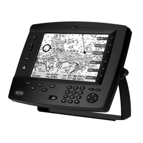
Choosing a system location The 961 consists of two major parts—a processor and a control head. The 961 supports two fully functional control heads (the second head is optional). The 961 system comprises the processor and control head, GPS receiver, optional differential receiver, controls, and the specially-coated display screen. -
Page 20: Figure 1: 961 Control Head Yoke-Mount Dimensions (Side)
SECTION TWO - Installation Page 10 12.4 Figure 1: 961 control head yoke-mount dimensions (side) 13.5 11.6 Figure 2: 961 control head yoke-mount dimensions (front) 12.4 961 INSTALLATION MANUAL Revision A... -
Page 21: Figure 3: 961 Control Head Flush-Mount Drilling Dimensions
Flush mounting For flush-mounting the unit, allow at least 2½-inch clearance at the rear for cables and connectors. For the recommended flush mounting drilling dimensions, see Figure 3 below. For the full-size version of the flush-mount installation measure- ments and instructions, refer to the full-size flush-mount template (P/N GT1600) included in the 961 shipping carton. -
Page 22: Wiring The 961
SECTION TWO - Installation For the processor installation measurements and instructions, refer to the Installing the full-size flush-mount templates, “961 Processor Mounting Template, top processor view” (P/N GM1700) and the “961 Processor Mounting Template, front view” (P/N GM 1701) included in the 961 shipping carton. To properly install the processor, you must first install the mounting bracket to the surface of the vessel, then attach the processor to the bracket. -
Page 23: Figure 4: Processor Connectors (Back Of Unit)
ing and prevents electrical fires. The power wiring should be connected directly to the battery when possible for optimum noise immunity. Electrical power The 961 is a negative-ground system. After the processor has been installed—but before you turn the 961 on—verify that the wires in the requirements 10-foot power cable are connected as follows: •... -
Page 24: Installing The Antenna
SECTION TWO - Installation Connectors • • • • • • • • • Installing the antenna Choosing an Three antenna choices are available for the 961X or 961XD: antenna • • • Choosing an Choosing the AN150 antenna location antenna location The GPS receiving antenna is a vital link between the unit’s receiver and the outside world. -
Page 25: Figure 5: Separation Distances Between Antennas
To avoid mutual interferences among different antennas on the vessel, refer to the drawing of recommended separation distances in Figure 5: ‘Separation distances between antennas,’ below. Figure 5 shows the minimum recommended distances for the separation of the GPS antenna from other antennas and physical mounting surfaces. Under normal circumstances, following these guidelines usually result in a relatively trouble-free installation. - Page 26 SECTION TWO - Installation antenna is desired. The AN205-P doesn’t require any ground and is porta- ble, an advantage when it must be moved from one vessel to another. The “combo” antenna should be located where it has a clear view of the hori- zon, but is not the highest point on the vessel.
-
Page 27: Figure 6: Gps-Only Antenna (An150)
Wiring the AN150 antenna Supplied with the antenna is a 50-foot length of RG-59 coaxial cable for use with either the GPS-only AN150 “active” antenna (as well as the GPS/ DGPS AN205-P “combo” antenna). Mounting the AN150 antenna Tools needed: •... -
Page 28: Figure 7: Stripping The Coax Cable Jacket
SECTION TWO - Installation 3. Feed the open end of the supplied coax cable down through the 4. Affix the TNC connector-end of the coax to the mating connector 5. Align the upper half of the antenna with the bottom half and tighten 6. -
Page 29: Figure 9: Completed Bnc Connector
The combo antenna provides for an easier, more compact, and bet- Installing the ter-looking installation, and in many cases, the loop antenna design AN205-P improves the noise rejection of signals interfering with differential signals. antenna Wiring the AN205-P antenna When you use the AN205-P combo antenna, a cable “splitter” is required to separate the signal path of the single cable from the antenna into two cables for connection to the 961. -
Page 30: Figure 11: Correct An205-P (Combo Antenna) Splitter Wiring
SECTION TWO - Installation ever, that the splitter isn’t weatherproof and should be placed in a pro- tected area where it won’t be subjected to direct water splash or spray. Avoid tight bends when installing any antenna cable. Be sure to fasten the cable along its length to avoid chafing or whipping of any kind. -
Page 31: Figure 12: Stripping The Coax Cable Jacket
Mounting the AN205-P antenna 1. Strip cable jacket to the following dimensions (in inches), as illus- 2. “Figure 13: Flared cable braid” below: Slide outer ferrule on as shown. 3. Place center contact onto center conductor so that it butts against 4. - Page 32 SECTION TWO - Installation If you want to receive differential corrections with the 961 and you’re Installing an 8410 using the AN150 antenna, you must use the Northstar 8410 Antenna ACU (for use with Coupling Unit (ACU). Although similar in appearance to Northstar loran the AN150 only) ACUs, only the unit labeled “8410”...
-
Page 33: Figure 15: Acu Assembly
body into which the upper half is secured (see Figure 15, “ACU Assem- bly”). A gasket and rubber O-ring on the upper half provide weathertight sealing when the two halves are secured. The bottom of the base is threaded (1"–14) to mount onto an antenna mast or onto a standard deck mount. -
Page 34: Figure 16: Correct An150 And 8410 Wiring
SECTION TWO - Installation RF grounding The grounding system is an equal partner with the antenna in producing quality differential beacon signals for the 961 differential receiver. Lack of proper grounding can adversely affect differential signal strength, as well as SNRs, and is the most common source of problems with differential antenna installations. - Page 35 The 8410 ACU has a separate black ground wire inside the coupler base, this wire should be connected to an electrically quiet ground location. This wire is the AC signal ground connection from the antenna input cir- cuit. The purpose of bringing it out is to make available a separate signal ground path.
-
Page 36: Turning The Unit On And Off
SECTION TWO - Installation Turning the unit on and off To activate the unit, briefly press the PWR key. This activates the control Turning the unit head and the processor. After several minutes, the INITIAL STARTUP screen appears (as shown in Figure 18 below). This screen displays for about five to ten seconds. -
Page 37: Figure 18: Initial Startup Screen
SECTION TWO - Installation Figure 18: Initial startup screen Figure 19: System test screen After the SYSTEM TEST screen, the 961 automatically displays the OWNER’S MESSAGE screen, as shown in Figure 20, for about 10 seconds. For information on creating a personal owner’s message (such as the owner’s name and name of the vessel), see “System security”... -
Page 38: Figure 20: Owner's Message Screen
SECTION TWO - Installation After the OWNER’S MESSAGE screen, the special advisory message is dis- Advisory played as a precautionary reminder that the unit’s chart cartography message must not be relied upon as the sole means of safe navigation. Although every effort has been made to ensure that the data used by the unit is as close to paper charts as possible, errors and omissions are inevitable. -
Page 39: Figure 21: Advisory Message
SECTION TWO - Installation Figure 21: Advisory message If chart CDs for your geographical area have been installed onto the 961’s hard drive, and after the unit acquires GPS signals, you’ll see your vessel symbol centered on the CHART screen at your present position. Until the 961 acquires GPS signals, the small position-fix circle will be located at the last known position. -
Page 40: Figure 22: Gps Satellite Status Screen
SECTION TWO - Installation Once the unit is turned on and has acquired satellite data, you can check the quality of the GPS signals being received by viewing the various satel- lites’ SNR (Signal-to-Noise Ratio) readings. GPS receiver status summary To display information about the GPS satellites, press the STAR key to display the SERVICE MENU screen, then press the GPS STATUS key. - Page 41 SECTION TWO - Installation and doesn’t consider atmospheric conditions, Selective Availability, and signal interference, all of which affect accuracy. HDOP can range from an ideal value of slightly less than one, up to a poor value of 10 or more; any value less than two indicates excellent performance.
-
Page 42: Testing And Troubleshooting The 961
SECTION TWO - Installation 1. Press and hold the PWR key for three seconds, and the 961 will turn To turn off an entire system (the two heads and the processor) with two control heads that are on: 1. Press and hold the PWR key for approximately two seconds until the 2. - Page 43 Table 2: Troubleshooting the installation (continued) Problem Area Symptom POWER (cont’d) The control head powers-up, but not the processor (the processor’s power indicator at the back of the unit is not lit). POWER (cont’d) The control head powers up, beeps, and the backlight can be operated up and down, but there isn’t any video.
- Page 44 SECTION TWO - Installation Table 2: Troubleshooting the installation (continued) Problem Area Symptom DISPLAY (cont’d) The display screen dims, either slightly or more, after the unit has been on for a cer- tain time. If the display screen dims and also displays the error message “unit too hot, backlighting dimmed.”...
- Page 45 Table 2: Troubleshooting the installation (continued) Problem Area Symptom PROCESSOR Vibration-related: (cont’d) System lock-ups The system locks up while underway under certain conditions. Systems tend to lock up on those vessels that are 35-55 feet in length with varying beam widths, having twin large displacement engines, moving approximately 20 to 35 knots, and with their processors installed at/or below the water-...
- Page 46 SECTION TWO - Installation Table 2: Troubleshooting the installation (continued) Problem Area Symptom PROCESSOR (cont’d) Configuration No GPS or DGPS DGPS There’s no DGPS indicator on the Chart (DIFFERENTIAL) screen, and: The BEACON RX SELF-TEST AND SOFT- WARE message says STAR key to access the SERVICE MENU screen, then press the...
- Page 47 Table 2: Troubleshooting the installation (continued) Problem Area Symptom DGPS (cont’d) There’s no DGPS indicator on the Chart screen, and: The BEACON RX SELF-TEST AND SOFT- WARE message reads THE DGPS STATUS SEARCHING DGPS (cont’d) There’s no DGPS indicator on the CHART screen, and: The BEACON RX SELF-TEST AND SOFT- WARE reads PASSED, and the DGPS...
- Page 48 SECTION TWO - Installation Table 2: Troubleshooting the installation (continued) Problem Area Symptom INTERFERENCE Electrical, magnetic, or radio frequency (RF) energy is interfering with the reliable opera- tion of the unit as shown by high levels of noise on the DGPS status screen. The head and processor power up, but poor GPS SNR readings are obtained even after running the unit for several minutes.
-
Page 49: Table 3: Troubleshooting The Gps/Dgps Antenna Installation
Table 3: Troubleshooting the GPS/DGPS antenna installation Antenna Symptom GPS ANTENNA Poor or no GPS signal while using the AN150 antenna. If 5.5 VDC low or missing with load con- nected: If 5.5 VDC low is missing with load discon- nected: If 5.5 VDC is present: DGPS ANTENNA... - Page 50 SECTION TWO - Installation Table 3: Troubleshooting the GPS/DGPS antenna installation (continued) Antenna Symptom DGPS ANTENNA No beacon signal (applies to all DGPS (cont’d) antennas): BCN RCVR ST If the If the coax and antenna are okay and there is 7.75 VDC: Page 40 Possible Solutions/Reasons •...
- Page 51 Table 3: Troubleshooting the GPS/DGPS antenna installation (continued) Antenna Symptom DGPS ANTENNA High beacon SNR or low signal. (cont’d) When vessel interference is still present: When the source of the interference is found: DGPS ANTENNA Poor, intermittent, or no beacon signal using (cont’d) a known-good loop or combo antenna.
-
Page 52: Table 4: Troubleshooting The Radar Interface
SECTION TWO - Installation b. Testing the GPS portion of the splitter and a combo antenna: When using a combo antenna and split- ter, the splitter gets 7.75 VDC from the beacon receiver, and then feeds the combo pre-amp with that same voltage level. - Page 53 Table 4: Troubleshooting the radar interface (continued) Component Symptom RADAR DEVICE There’s bearing-pulse interference from the radar (this also applies to depth sounders). 961 INSTALLATION MANUAL Revision A SECTION TWO - Installation Possible Solutions/Reasons • The radar’s scanning cables may be too closely bundled with the 961’s control head-to-processor coax cable: Run the cables of the radar and the 961 on...
- Page 54 SECTION TWO - Installation Page 44 961 INSTALLATION MANUAL Revision A...
-
Page 55: Section Three - Interfacing
SECTION THREE - Interfacing his chapter includes the information needed to interface the 961 to other equipment on the vessel. Major topics include: • • • • Interfacing the unit The unit is easily interfaced to other equipment as described below. NMEA 0183 is the most common interface data format used with installa- tions, and it is a widely-accepted standard of data transfer between most all types of marine electronics today, enabling completely different instru-... -
Page 56: Configuring The Nmea Output Ports
SECTION THREE - Interfacing Configuring the NMEA output ports Each output port can be programmed to meet most any special require- ments of devices that conform to the NMEA 0183—and other—data for- mat specifications. The service function described below allows the selection of the specific 0183 sentences that will be transmitted by the 961. -
Page 57: Figure 24: Port 1 Output Setup Screen
Check the installation instructions of the equipment to which you’re interfacing for any special requirements. The Northstar factory settings will be adequate for most peripheral equipment, but the following options are available, if needed: Parameter OUTPUT FORMAT (see below) NMEA 0183 Talker ID (see page 51) NMEA 0183 lat/lon precision (see page 52) - Page 58 SECTION THREE - Interfacing The unit will output navigation data in any of several standard formats as Setting the required by the receiving, or “listener,” device. Upon pressing the EDIT output format menu key at this option, you’ll find the following choices available: NMEA 0180, NMEA 0183, (DATAMARINE) CDX, 0183-R, and OFF.
-
Page 59: Figure 25: Port 1 Output Setup (Sentences) Screen
light the FORMAT field (for either 0183 or 0183 RAY), then press the 0183 DATA key to display the sentences. About the NMEA The 961 also supports the NMEA TLL sentence, sometimes referred to as the “rattle” sentence. This sentence allows the 961 to communicate its TLL sentence position to an interfaced radar device, which tracks a user-defined target. - Page 60 SECTION THREE - Interfacing 0183 identifier RNN V1.5 Modifying NMEA output sentences On the screen, the highlighted sentences will be output, as shown earlier in Figure 25. Some devices can’t handle all of these sentences correctly, so you can use this screen to customize the output by turning individual sentences on or off.
-
Page 61: Figure 26: Port 1 Output Setup Screen
To set the output sentences to the factory default settings, press the DEFAULTS ON key. To turn on only a select few sentences, press the CLEAR ALL key, then turn the desired sentences back on. To modify the unit’s NMEA 0183 sentence output format, first follow the above description to display the 0183 sentence screen, then perform the following steps: 1. - Page 62 SECTION THREE - Interfacing 2. At the PORT OUTPUT SETUP screen, select the desired port, then 3. Press the EDIT key, and highlight the desired ID. 4. Press ACCEPT key (or CANCEL to leave the option unchanged). The For added versatility in communicating with a variety of other devices, Setting NMEA you can control how precisely the 961 outputs its lat/lon information.
-
Page 63: Setting The Auxiliary Port
The 961 normally uses a two-second update interval for data transmis- Changing the sion. Some applications require a longer update period, so the 961 lets output rate you increase that span to 199 seconds. You can choose a one-second interval, but at that rate, the bandwidth of 4800-baud NMEA data only allows the output of a reduced set of sentences. -
Page 64: Figure 27: Auxiliary Port Setup Screen
SECTION THREE - Interfacing differential corrections). If the 961 already has an internal differential receiver, you can use the aux port to transmit its differential corrections to another device that accepts them. To access the aux port options: 1. Press the STAR key to access the SERVICE MENU screen. 2. -
Page 65: Setting Ppnm
Aux port format Outputting DGPS corrections to another source SC-104 OUT outputs differential corrections from your 961XD’s internal differential receiver to an external device that accepts the standard SC-104 data stream. When using the SC-104 OUT setting, be sure that the BAUD setting also matches the baud rate requirements of the receiving device. -
Page 66: Using Vga Output
SECTION THREE - Interfacing The following configuration parameters are available as outlined in Table 9 below. Parameter Pulses per nautical mile Pulse time minimum Pulse separation time The 961’s PPNM default settings are 200 ppnm, 100 milliseconds, and 200 milliseconds. To change the PPNM settings: 1. -
Page 67: Section Four - Service/Maintenance
SECTION FOUR - Service/Maintenance Service functions This section explains the options at the SERVICE MENU screen for view- ing product information, configuring the receivers, viewing GPS status, and saving and restoring databases and system logs. The port setup option is also introduced here, but described in detail in this manual in “Section Three, Interfacing.”... - Page 68 SECTION FOUR - Service/Maintenance Processor serial number and software revision The serial number of the processor is affixed to the back of the unit, and also has been permanently programmed into the unit’s database. You can view this serial number at the PRODUCT INFORMATION screen in the PROCESSOR SN/REV field.
-
Page 69: Figure 30: Receiver Information Screen
Changing GPS speed averaging value When you aren’t using DGPS or you’re out of range, you may notice that the SOG readings obtained from the GPS satellite system are slightly erratic, varying by up to several knots. The 961’s GPS SPEED AV function often can improve the steadiness of these readings, although you’ll see a slightly longer display-reaction time when the speed changes. - Page 70 SECTION FOUR - Service/Maintenance You can change the speed averaging value at any time without affecting other navigation functions. To change the speed averaging value: 1. At the RECEIVER INFORMATION screen, press the CURSOR PAD to 2. Press the CURSOR PAD left or right to select an averaging time in 3.
- Page 71 Setting beacon frequency and baud rate You can set the receiver to operate automatically or be controlled manu- ally. Automatic tuning Northstar’s two-channel differential receiver enters automatic differential mode as soon as corrections are received, and doesn’t require any further supervision for differential operation, automatically tuning to the appro- priate differential frequency as you move from one differential coverage area to another or as weather conditions change.
-
Page 72: Figure 31: Gps Satellite Status Screen
SECTION FOUR - Service/Maintenance can set the differential frequency to any value between 283.5kHz and 325kHz. You can set the baud rate to any of the four standard rates: 25 bps, 50 bps, 100 bps, or 200 bps. To choose manual mode: 1. - Page 73 For an overview of GPS and DGPS, see “Introducing GPS and DGPS” in Chapter 2 of the Northstar 961 Operations and Reference Manual (GM1700). For details about the GPS satellite status screen, see “Under- standing Position Coordinates” in Chapter 5 of the Northstar 961 Opera- tions and Reference Manual (GM1700).
-
Page 74: Figure 32: Database Function Screen
SECTION FOUR - Service/Maintenance A blank, properly formatted floppy disk always has enough space to store your backed-up databases (a Zip disk also has enough space). If you receive the message “Unable to copy data to the removable disk,” check if the disk is write-protected: To change the write-protection status of a floppy disk, use the tip of a pen to switch the position of the small square on the outer corner of the disk. -
Page 75: Figure 33: Select Database To Save Dialog Box
The SAVE DATA dialog box appears, defined as either user preference data, waypoint and route data, or all data, depending on which of the above options you chose. 3. Insert the disk into the drive (either a floppy disk or a Zip disk), then 4. -
Page 76: Figure 34: Select Database To Restore Dialog Box
SECTION FOUR - Service/Maintenance The RESTORE DATA dialog box appears, defined as either user preference data, waypoint and route data, or all data, depending on which of the above options you chose. 3. Insert the disk into the drive (either a floppy disk or a Zip disk), then 4. -
Page 77: Figure 35: Select A Restored Database To Undo Dialog Box
2. Press the CONFIRM key. The 961 removes the restore files from the Saving log data Occasionally, the 961 may have a problem that requires looking at its log files to determine the cause. If this happens, you’ll be prompted to save the 961’s log files, which should then be sent to the Northstar Service Department. -
Page 78: Maintenance Functions
SECTION FOUR - Service/Maintenance 3. Insert the disk into the drive (either a floppy disk or a Zip disk), then 4. Press the CONFIRM key to return to the DATABASE FUNCTION Maintenance functions Cleaning the 961 To clean the glass lens of the control head, use a commercially available glass cleaner. -
Page 79: Appendix A - Technical Specifications
APPENDIX A - Technical Specifications Northstar 961 Power Source: Power Power Consumption: Fuse: Operating Power: Type: GPS receiver Sensitivity: Navigation Accuracy: Navigation Update Rate: Time To First Fix: Dynamics: Operating Modes: SC-104: types, Interfacing • • • • • • •... -
Page 80: Physical Features
APPENDIX A - Technical Specifications • • • • • Physical features Control head • • • • • • • • • • Processor • • • • Environmental Head • • Processor • Page 70 External SAVE input Waypoint download capability Operating software upload (updates) NMEA output sentences: APB, BOD, BWC, GGA, GLC, GLL, GSA,... -
Page 81: Internal Beacon Receiver Specifications (961Xd)
Internal beacon receiver specifications (961XD) Signal processing Noise Blanker: Signal Detection: Turning Resolution: Type: Frequency Range: Minimum Signal Strength: Dynamic Range Adjacent Channel Rejection: Acquisition Time Data processing Demodulation: Bit Rates: Data Decoding: Power Power consumption: AN150 Active GPS Antenna Height: Diameter: Weight:... -
Page 82: 8410 Antenna Coupling Unit
APPENDIX A - Technical Specifications 8410 Antenna Coupling Unit Height: Diameter: Weight: DGPS Whip Antenna: AN205-P GPS/DGPS antenna • • • • • • • • • • • • • • • Page 72 11 inches 2.6 inches 1.5 pounds 48-inch fiberglass whip (not supplied) (Shakespeare 4' #173 loaded, or Radio Shack #21-934) - Page 83 Numerics 8410 ACU assembly diagram 23 cables 23 components 22 evaluating temporary locations before mounting 22 mounting 22 technical specifications 72 using the AN205-P antenna with 22 using with the AN150 antenna 22 wiring with AN150 antenna 24 activating 26 interfacing 45 servicing and maintaining 57 testing and troubleshooting 32...
- Page 84 data transmission, changing update intervals database, saving and restoring 63 DATAMARINE CDX output format 48 DGPS antenna connector (UHF) 14 antenna. See AN205-P antenna checking for the presence of signals 32 outputting aux port corrections 55 receiver setting beacon frequency and baud rate 61 turning DGPS on and off 60 troubleshooting 36...
- Page 85 yoke vs. flush 9 mounting bracket 12 MSS 0183 identifier 50 NMEA 0180 output format 48 NMEA 0183 baud rate 47 checksums 47, 53 lat/lon precision 47 output format 48 sentence identifiers 49 Talker ID 47 talker ID 51 waypoint ID 47, 53 NMEA output configuring ports 46 displaying sentences 48...
- Page 86 service 3 setup parameters aux port 54 PPNM output 56 shading avoiding electromagnetic 16 shipping carton, checking for damage 6 shipping charges 3 shortcuts, avoiding 7 Signal-to-Noise Ratio 22 grounding and showing for each satellite 30 troubleshooting poor readings 16, 19 silicone dielectric grease 25 SNR.