
Related Manuals for NorthStar 957


Summary of Contents for NorthStar 957
- Page 1 957 GPS/W HART AVIGATOR NSTALLATION ANUAL Revision C1 Part Number GM957IM Northstar Technologies 30 Sudbury Road Acton, Massachusetts 01720 800/628-4487 978/897-6600 www.northstarcmc.com...
- Page 2 Call the Northstar dealer or Northstar for instructions. During the unit’s warranty period, Northstar will repair or replace, at its option, any part of the unit it finds to be defective due to faulty material(s) or workmanship. All such repairs and/or replacements will be promptly performed by Northstar free-of-charge to the owner, excluding freight costs incurred in shipping to the factory.
-
Page 3: Table Of Contents
Major installation steps ............2 SECTION TWO: Installing and wiring the 957 ....... 5 Safety considerations . - Page 4 Troubleshooting 957 installation problems ........
-
Page 5: Section One: Introduction
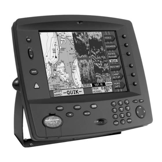
Introduction The Northstar 957 is a full-featured color GPS/WAAS vector chart navigator. The 957 can be connected with a variety of optional equipment such as the Northstar 490 echo sounder, and with VGA output equipment such as the Northstar 1201 remote display. -
Page 6: Scope Of This Manual
Northstar factory for service. Step 2. Fill out the warranty card and mail it to Northstar. Step 3. Unpack the carton, and check its contents. You should have received the following parts: •... - Page 7 Section Two and Section Three. Step 2. Make sure you have all the right tools before starting the installation. Step 3. Install the 957—see “Mounting the 957” beginning on page 6. Step 4. Install the 2201 and cable— see “SECTION THREE: Installing and wiring the 2201”...
- Page 8 Step 5. (Optional) Install and connect the Northstar 490 Echo Sounder. For instructions, see the Northstar 490 Installation Manual (part number GM491). Step 6. Connect the 957 to ship’s power, the 2201 or 2701, and optionally, the 490—see ”Wiring the 957” on page 13. POWERING UP AND INTERFACING: Step 1.
-
Page 9: Section Two: Installing And Wiring The 957
Be sure to ground the equipment to prevent electrical shock and mutual interference. Be sure to use the proper fuse. Using the wrong fuse can cause fire or damage to the 957. Page 5... -
Page 10: Bench-Testing The 957
Choose the mounting location carefully—before you drill or cut. The display screen is high-contrast and anti-reflective, and is viewable in direct sunlight, but for best results, install the 957 out of direct sunlight. See the figure below for additional mounting recommendations. - Page 11 SECTION TWO: Installing and wiring the 957 Regardless of the type of mounting, the 957 should be installed in an accessible location (dry) where the operator can easily use the controls and clearly see the display screen. Be sure to leave a direct path for all of the cables.
- Page 12 CAUTION! When flush mounting, be sure to mount the 957 on a flat surface. Mounting on a curved surface can break or distort the plastic and break the waterproof seal.
- Page 13 SECTION TWO: Installing and wiring the 957 Figure 2: 957 flush-mount clearance dimensions 957 Installation Manual, Revision C1 Page 9...
- Page 14 SECTION TWO: Installing and wiring the 957 Yoke-mounting the 957 Page 10 Before drilling, turn the 957 to the desired angle on the yoke to make sure there’s enough space for the cables. Leave clearance space as follows: • at least 2 inches of space all around the sides and the top •...
- Page 15 SECTION TWO: Installing and wiring the 957 6.1” 1.9” 12.4” 2.3” 8.2” Figure 3: 957 yoke-mount dimensions (side) 957 Installation Manual, Revision C1 Page 11...
- Page 16 SECTION TWO: Installing and wiring the 957 13.5” 12.4” 11.6” Figure 4: 957 yoke-mount dimensions (front) Page 12 957 Installation Manual, Revision C1...
-
Page 17: Wiring The 957
957 Installation Manual, Revision C1 SECTION TWO: Installing and wiring the 957 Most installation problems are caused by shortcuts taken with system cables. When wiring the 957, follow the guidelines illustrated in Figure 5 below. DON’T DO THIS! Do not run cables in such a way that... - Page 18 (18-pin port) GPS (Antenna) (7-pin RS232 port) Page 14 All of the 957’s interface connectors are shown in Figure 6: ”Interface connectors (back of 957),” below. The function of these connectors is described in Table 1, below. AUX connector NMEA connector...
- Page 19 957 to a circuit breaker or 20-amp fuse at the power source (battery). A 10-foot power cable is shipped with the 957 system. You can lengthen this cable to a maximum of 25 feet: •...
- Page 20 Page 16 The power cable has an inline fuse to protect the vessel’s wiring, prevent electrical fires, and prevent damage to the 957. If you shorten this cable, be sure to keep the inline fuse intact. The wires in the power cable must be connected as follows.
-
Page 21: Section Three: Installing And Wiring The 2201
The Northstar 2201 GPS pod is a self-contained, high performance GPS antenna/receiver that also receives Wide Area Augmentation System (WAAS) differential correction signals. When connected to the 957, the 2201 provides the 957 with WAAS-enhanced GPS position information. For the 2201’s technical specifications, see Table 15, “2201 technical specifications,”... -
Page 22: Installing The 2201
Choosing the best mounting location Page 18 NOTE: Before permanently temporarily installing it and using the 957 to see if the 2201’s location works well. The 2201 includes the following parts (see Figure 7: ”2201 antenna components,” below): • 2201 GPS/WAAS pod •... - Page 23 Figure 8: Recommended separation distances between antennas Mounting the 2201 957 Installation Manual, Revision C1 SECTION THREE: Installing and wiring the 2201 • below the radiation plane of any INMARSAT or radar antennas, and away from any other high-power transmitting antennas (see Figure 8 on page 19).
- Page 24 You can mount the 2201 onto a deck or any other flat surface: Using the three screws and washers provided, mount the 2201 onto the flat surface using three holes on a 1.75-inch diameter circle (see Figure 10 below). 4.50” (114mm) 957 Installation Manual, Revision C1...
-
Page 25: Wiring The 2201
You can shorten the 957POD-CA cable, but do not lengthen it. The cable must be a maximum of 50 feet. The 50-foot 957POD-CA cable connects the 957 with the 2201. Both ends of the cable are finished with 7-pin connectors that plug into the 2201 and 957: Plug the 2201 end of the cable into the 2201, and the 957 end into the 957 connector labelled “GPS.”... - Page 26 7. Heat the shrink tubing until it shrinks around the connector, providing a watertight seal. For the pin numbers and functions for the 957 end of the cable, see Table 2 below. Table 2: Wiring connections for 2201 cable...
- Page 27 Remote power-on Ship’s power control Power gnd (system gnd) Power in (9-36 VDC) The 957 has four settings for differential operations. For instructions on choosing the correct setting, see ”Selecting differential options” starting on page 36. Wire color Black White...
- Page 28 SECTION THREE: Installing and wiring the 2201 Page 24 957 Installation Manual, Revision C1...
-
Page 29: Section Four: Installing And Wiring The 2701
957 Installation Manual, Revision C1 SECTION FOUR: Installing and wiring the 2701 The Northstar 2701 is a high-performance, fully automatic 12-channel GPS/WAAS receiver and a two-channel beacon receiver packaged into a self-contained enclosure. The 2701 receives differential corrections from ground-based radiobeacons as well as from satellites transmitting WAAS differential signals. -
Page 30: Installing The 2701
The 2701 includes the following parts: • 2701 DGPS/WAAS receiver • 10-foot data/power cable for connecting the 2701 to the 957 (both cable ends are finished) • AN205-P GPS/DGPS combination antenna • 50-foot antenna cable for connecting the 2701 to the... -
Page 31: Wiring The 2701
The 10-foot 957BDM-CA cable connects the 957 with the 2701. Both ends of the cable are finished with connectors that plug into the 2701 and 957. Plug the cable’s 25-pin connector into the 2701, and the 7-pin connector into the 957 connector labelled “GPS.”... -
Page 32: Installing The An205-P Antenna
Keep the antenna at least six feet away from objects that can “shade” GPS or differential signals. NOTE: Before permanently installing the AN205-P, try temporarily installing it and using the 957 to see if the antenna location works well. 957 Installation Manual, Revision C1... - Page 33 Note: Installations that require a cable length from 50 to 100 feet should order the AN206 combo antenna and a 100-foot length of coaxial cable from the Northstar Sales Department. Don’t make any tight bends in the cable, and fasten it along its length to avoid chafing or whipping or any kind.
- Page 34 SECTION FOUR: Installing and wiring the 2701 Page 30 957 Installation Manual, Revision C1...
-
Page 35: Section Five: Checking Out The System
The cartridge slot is located at the lower left-hand corner of the 957. Before inserting a Navionics chart cartridge, make sure its label is facing up and that the cartridge is oriented as shown in Figure 13 below. Insert the cartridge gently but firmly into position with one straight, smooth motion. - Page 36 Improper handling and storage of the cartridge may damage the 957. Such damage isn’t covered under the 957 warranty. Page 32 Figure 13: Properly inserting a chart cartridge 957 INSTALLATION MANUAL, Revision C1...
-
Page 37: Turning The 957 On And Off
957 INSTALLATION MANUAL, Revision C1 SECTION FIVE: Checking out the system To turn on the 957, briefly press the PWR key. The 957 emits several short beeps as it displays the START-UP screen, then the 957 performs a series of self-tests to check its critical components and functions. - Page 38 (DGPS) system if the 957 is connected to the optional Northstar 2701 receiver. To see if the 957 is using WAAS or DGPS, press the CHART key to display the GPS POSITION screen and look for the WAAS or DGPS indicator below and to the right of the lat/lon display.
- Page 39 Figure 14: Satellites on the GPS satellites screen The satellite map on the GPS SATELLITES screen shows the current location of the satellites in the sky. The 957 displays GPS satellites as circles; WAAS satellites as hexagons. You can check the quality of their signals by looking at each satellite’s Signal-to-Noise Ratio (SNR).
- Page 40 You can override the auto-dim function at any time by increasing the brightness with the BRIGHTNESS key. The 957 may dim again as required so as not to exceed the maximum internal temperature. If you point the remote directly at the 957 and are within nine feet, you can operate all of the 957’s keys except the PWR key.
-
Page 41: Installation-Test Checklist
957 INSTALLATION MANUAL, Revision C1 SECTION FIVE: Checking out the system To check-out the 957 system after installation: Turn on the 957, then check for the presence of GPS, WAAS, or DGPS signals. Review the functions: With a chart cartridge inserted, check that the CHART screen is displayed. - Page 42 SECTION FIVE: Checking out the system Page 38 957 INSTALLATION MANUAL, Revision C1...
-
Page 43: Section Six: Interfacing The 957 System
Wiring the connector pins 957 INSTALLATION MANUAL, Revision C1 SECTION SIX: Interfacing the 957 system The 957 has the following interface ports: • NMEA 1 and 2 input and output (on the 18-pin NMEA connector) • 7-pin GPS connector •... - Page 44 SECTION SIX: Interfacing the 957 system Page 40 Table 5: NMEA connector pins Description Wire color NMEA port 1 input A brown NMEA port 1 input B blue NMEA port 1 input ground white with blue stripe NMEA port 1 output A...
-
Page 45: Configuring The Nmea Output Ports
* Pin 1 on the AUX port requires two connections from the cable. The red wire is not connected on the 957 end, and should be insulated and capped. For the aux port pin configuration, see Figure 17 on page 51. - Page 46 Choosing the output format Page 42 The devices you’re interfacing with the 957 may have special requirements, so check their installation instructions. The Northstar factory settings are fine for most peripheral devices, but the following options, as described below, are available if needed.
- Page 47 957. Turning NMEA output sentences on and off To turn on or off the 957’s NMEA 0183 sentences, first follow the above description to display the 0183 SENTENCE screen, then follow these steps: Press the CURSOR PAD to highlight the sentence you want to turn on or off, then press the EDIT menu key.
- Page 48 Certain listening devices will only accept navigation data identified as coming from loran (LC), GPS (GP), or an integrated instrument (II). The 957 lets you set its talker ID to LC, GP, or II to match what the listener device is expecting: Check the listener device’s instruction manual to...
- Page 49 In that case, you can increase the span to 999 seconds. Many marine devices can display waypoint names if they’re output by the 957. At the PORT 1 SETUP or PORT 2 SETUP screen, highlight the NMEA 0183 WAYPT ID AS option, then press the EDIT menu key.
-
Page 50: Using 200 Ppnm Output
Some older devices may not accept sentences containing the NMEA 0183 checksum that’s output by the 957. In such cases, the device may not work properly or at all. If you have... -
Page 51: Configuring The Rs-232 Port
When using SC-104 IN, be sure that the BAUD RATE setting also matches the beacon receiver’s baud rate requirements. The COPY PORT setting lets you interface the 957 to many PC’s without using an RS422-to-RS232 converter. Many PC application programs can be used for waypoint/route loading, chart programs, data logging, etc. - Page 52 , and one of the copied ports is in 0183 output mode—unless the diagnostic port’s baud rate is fast enough to handle the number of characters. Because the diagnostic port’s baud rate can now be changed, the 957 will always display this precautionary message before you actually reset baud SENTENCES MAY NOT TRANSMIT AT DIAG BAUD RATE.
-
Page 53: Connecting The 957 To A Remote Display
Northstar 957 Operator’s Manual (part number GM957UG). The 957 can be set to interface with a radar device. The 957 supports the NMEA TLL sentence, sometimes referred to as the “rattle”... -
Page 54: Connecting Two Northstar Units
957. You must select a cable; use only shielded, twisted pair. You can also connect a 957 with a Northstar 952, 951, or 941, also using your own data-transfer cable. Each 952, 951, and 941 that you want to transfer waypoints and routes to or from must be using software version 3.12 or higher. - Page 55 Ground/shield No connect Aux input B Aux output A Aux output B Aux input A Figure 17: 957 aux ports’ interface diagram (wiring side view, solder cup) Pin # Ground shield No connect Aux In B Aux Out A Aux Out B...
- Page 56 No connect Aux input B Ground/shield Aux output B Aux input A Aux output A No connect Figure 18: 952/951/941 and 957 aux ports’ interface diagram (wiring side view, Page 52 Shield termination AUX CONNECTOR 957 6-PIN Pin number Ground/shield...
-
Page 57: Setting The Anchor-Watch Alarm Honk
5. Install the strain- relief clamp with two screws. 6. Connect each end of the cable into the 6-pin ports at the back of the 957, or connect one end of the cable into the 10-pin port at the back of the 941, 951, or 952. - Page 58 SECTION SIX: Interfacing the 957 system Page 54 the wiring to support the 957’s external honk feature. You can use Radio Shack part number 273-060 or an equivalent. Figure 19: Pin 14 honk alarm connection A continuous honking sequence will begin, either when the vessel moves outside the specified anchor-alarm radius or when the navigation source becomes unavailable—once you’ve...
-
Page 59: Section Seven: Troubleshooting And Servicing The 957 System
957 INSTALLATION MANUAL, Revision C1 SECTION SEVEN: Troubleshooting and servicing the 957 system Typical problems that may occur during or after the 957’s installation are described in the tables below. Possible Solutions/Reasons • key doesn’t start the Check the fuse and the power to the 957. - Page 60 Table 10: Troubleshooting the 957 installation (continued) Problem Area Symptom • DISPLAY (cont.) The display screen dims, either slightly or more, after the 957 has been on for a certain time. • The message where the video input image should be. •...
- Page 61 Make sure the antenna is clean, and not covered with ice, snow, or exhaust soot. Check that WAAS is available in your operating area. Reset the 957’s satellite elevation setting to its default (10 degrees). DIFFERENTIAL OPERATIONS Check that the 957’s WAAS AUTO.
- Page 62 Make sure the antenna is clean, and not covered with ice, snow, or exhaust soot. Check that WAAS is available in your operating area. Reset the 957’s satellite elevation setting to its default (10 degrees). DIFFERENTIAL OPERATIONS Check that the 957’s...
-
Page 63: Getting Technical Support
PDF form) or Support links. 957 INSTALLATION MANUAL, Revision C1 SECTION SEVEN: Troubleshooting and servicing the 957 system After you’ve followed the instructions in this manual, if you need technical assistance or have any other service-related questions, you can contact the Northstar Service Department. -
Page 64: Hearing From You
(you can send email to Northstar directly from this site) Your feedback is important and helps Northstar ensure that this manual is a valuable resource for all marine technicians. Email your comments or suggestions about this manual to the following address: manuals@northstarcmc.com... -
Page 65: Servicing The 957 System
For a system under warranty, shipping charges to the factory are the only cost for factory repair. The repaired 957 will be returned via prepaid economy ground freight (units returned overseas are chargeable). -
Page 66: Returning A 957 System For Service
Northstar Technologies Service Department 30 Sudbury Road Acton, MA 01720 USA At the end of the day, wipe the 957 off with a damp cloth. Cover it with the sunshield to protect it from excessive heat. 957 INSTALLATION MANUAL, Revision C1... -
Page 67: Appendix A: 957 System Technical Specifications
RMA, RMB, VTG, WCV, XTE, ZDA, ZTG. (Conforms to NMEA v 2.0 and later. Supports 1.5 GLL and BWC.) Accepts most external loran receivers Waypoint and route transfer between two 957’s (or a 957 and a Northstar 941/951/952) Page 63... - Page 68 APPENDIX A: 957 system technical specifications Table 15: 2201 technical specifications Physical features Self-contained 12-channel L1 GPS/WAAS pod antenna-receiver. Dimensions: 4.5" (114mm) diameter x 3.79" (96mm) high. Weight: 1.2 lb. maximum excluding cable (0.55 kg). Cable (normal installation): 22 Ga conductors foil-shielded cable, environmentally sealed (50-foot cable supplied).
- Page 69 (60-minute obscuration). Channels allocation: 10 GPS channels plus two WAAS satellites. 957 INSTALLATION MANUAL, Revision C1 APPENDIX A: 957 system technical specifications Interfacing Primary power: 10 to 40 VDC (12V and 24V systems). 10 watts typical. RS-232, GPS, and beacon receiver comm ports...
- Page 70 APPENDIX A: 957 system technical specifications Page 66 957 INSTALLATION MANUAL, Revision C1...