Toro Reelmaster 5610 Operator's Manual
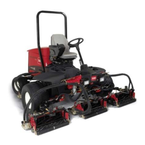
Traction unit
Hide thumbs
Also See for Reelmaster 5610:
- Owner's/operator's manual (56 pages) ,
- Service manual (662 pages) ,
- Operator's manual (60 pages)

Related Manuals for Toro Reelmaster 5610


Summary of Contents for Toro Reelmaster 5610
- Page 1 Form No. 3450-187 Rev A Reelmaster ® 5610 Traction Unit Model No. 03678—Serial No. 410500000 and Up Model No. 03678TE—Serial No. 409900000 and Up *3450-187* Register at www.Toro.com. Original Instructions (EN)
- Page 2 Whenever you need service, genuine Toro parts, or additional information, contact an Authorized Service Dealer or Toro Customer Service and have the model and serial numbers of your product ready. Figure 1 identifies the location of the model and serial numbers ©...
-
Page 3: Table Of Contents
Contents Servicing the Air Cleaner ........44 Checking the Engine-Oil Level......44 Servicing the Engine Oil and Filter ....45 Safety ............... 4 Fuel System Maintenance ........46 General Safety ........... 4 Draining the Fuel-Water Separator ....47 Safety and Instructional Decals ......5 Bleeding the Fuel System ......... -
Page 4: Safety
Safety Storage Safety..........65 Preparing the Traction Unit ....... 65 Preparing the Engine ........65 This machine has been designed in accordance with Storing the Battery ..........65 EN ISO 5395. General Safety This product is capable of amputating hands and feet and of throwing objects. -
Page 5: Safety And Instructional Decals
Safety and Instructional Decals Safety decals and instructions are easily visible to the operator and are located near any area of potential danger. Replace any decal that is damaged or missing. decal106-6754 decalbatterysymbols 106-6754 Battery Symbols 1. Warning—do not touch the hot surface. Some or all of these symbols are on your battery. - Page 6 decal110-8921 110-8921 1. Traction unit speed 2. Slow 3. Fast decal110-9642 110-9642 1. Stored energy hazard—read the Operator's Manual. 2. Move the cotter pin to the hole closest to the rod bracket and then remove the lift arm and pivot yoke. decal121-5644 121-5644 1.
- Page 7 decal145-5261 145-5261 1. Read the 4. Electric 7. TEC controller Operator's Manual for fuse information. 2. Power point (12 5. Engine start 8. TEC controller 3. Headlights 6. Air ride seat 9. TEC controller suspension (optional) decal133-2930 133-2930 1. Warning—do not operate this machine unless you are trained. 4. Tipping hazard—drive slowly when turning; do not turn sharply while traveling fast;...
- Page 8 CE Machines decal133-2931 133-2931 Note: This machine complies with the industry standard stability test in the static lateral and longitudinal tests with the maximum recommended slope indicated on the decal. Review the instructions for operating the machine on slopes in the Operator’s Manual as well as the conditions in which you would operate the machine to determine whether you can operate the machine in the conditions on that day and at that site.
- Page 9 decal136-3721 136-3721 1. Read the Operator’s 6. Engine air filter 11. Engine coolant 16. Fluids Manual for lubrication information. 2. Brake functions 7. Engine oil 12. Engine oil level 17. Capacity 8. Fan belt 13. Fuel 3. Check every 8 hours. 18.
-
Page 10: Setup
Install the cutting units. Left front hose guide Rear weights (size varies with Install rear weights (order from your Varies configuration) Toro Distributor). Hood lock, seal, and jam nut Install the CE hood lock. Washer Cutting-unit kickstand Install the cutting-unit kickstand. -
Page 11: Adjusting The Control-Arm Position
Adjusting the Control-Arm Installing the Cutting Units Position Parts needed for this procedure: Right front hose guide No Parts Required Left front hose guide Procedure Preparing the Machine The control-arm position can be adjusted for your comfort. Remove the reel motors from the shipping brackets. - Page 12 g003320 Figure 5 1. Counterweight g375689 Figure 7 1. Hairpin Positioning the Turf Compensating Remove the 2 flange locknuts (3/8 inch) and 2 Spring and Installing the Hose carriage bolts (3/8 x 1-1/4 inches) that secure Guide the turf-compensator bracket to the cutting-unit frame (Figure Cutting Units 4...
- Page 13 g375691 Figure 9 g375687 Figure 11 1. Capscrew 3. Flange locknut (3/8 inch) 2. Right tab (Carrier frame) 1. Turf-compensator bracket 3. Stud (hose guide) 2. Flange locknut (3/8 inch) 4. Inboard Assemble the capscrew of the turf compensation spring to the right tab of the carrier frame (Figure Assemble the hose guide and turf-compensator 10) with the flange locknut (3/8 inch).
- Page 14 g375688 Figure 15 1. Stud (hose guide ) 3. Flange locknut (3/8 inch) 2. Turf-compensator bracket 4. Inboard Assemble the hose guide and turf-compensator bracket to the cutting-unit frame with the 2 flange g375689 Figure 13 locknuts (3/8 inch). 1. Hairpin Torque the locknuts to 37 to 45 N∙m (27 to 33 ft-lb).
- Page 15 g375691 Figure 19 1. Capscrew 3. Flange locknut (3/8 inch) 2. Right tab (Carrier frame) Assemble the capscrew of the turf compensation spring to the right tab of the carrier frame (Figure 20) with the flange locknut (3/8 inch). g375689 Figure 17 1.
- Page 16 Installing the Front Cutting Units to the Lift Arms Slide a cutting unit under the lift arm (Figure 23). g378789 Figure 21 1. Turf-compensator bracket 3. Flange locknut (3/8 inch) 2. Carriage bolt (3/8 x 1-1/4 4. Inboard inches) g375274 Figure 23 Assemble the turf-compensator bracket to the 1.
- Page 17 Installing the Rear Cutting Units to the Lift Arms Cutting Units adjusted for a 1.2 cm (3/4 inch) or Higher Height of Cut Slide a cutting unit under the lift arm (Figure 25). g375251 Figure 26 1. Snap-pin positions 3. Slot (lift-arm pivot shaft) 2.
- Page 18 g375239 Figure 30 1. Lynch pin 3. Lift arm 2. Lift-arm shaft 4. Washer Insert the lift-arm shaft into the lift arm, and g375237 secure shaft to the arm with the lynch pin and Figure 28 washer. 1. Cap 3. Lift-arm yoke Repeat steps through for the other rear...
- Page 19 g004127 Figure 32 1. Reel-drive motor 2. Mounting bolts Rotate the motor counterclockwise until the flanges encircle the bolts, and then tighten the bolts. Important: Make sure that the reel motor hoses are not twisted, kinked, or at risk of being pinched.
-
Page 20: Installing Rear Weights
This machine complies with EN ISO 5395 and ANSI B71.4-2017 when equipped with rear weights and/or 41 kg (90 lb) of calcium chloride ballast is added to rear wheels. Use the following charts to determine the combinations of weights required for your configuration. Order parts from your local authorized Toro distributor. Weight P/N 110-8985-03... -
Page 21: Installing The Ce Hood Lock
Remove the 3 bolts, washers, and spacers securing the traction manifold to the bottom of the rear bumper (Figure 33a). Position the appropriate amount of weight on the top and/or bottom of the rear bumper. Mount the weight(s) and the traction manifold to the bumper with the 3 bolts, washers and spacers previously removed (Figure 33b). -
Page 22: Using The Cutting-Unit Kickstand
Using the Cutting-Unit Kickstand Parts needed for this procedure: Cutting-unit kickstand Procedure Whenever you must tip the cutting unit to expose the bedknife/reel, prop up the rear of the cutting unit with the kickstand to ensure that the nuts on the back end g004144 of the bedbar adjusting screws are not resting on the Figure 37... - Page 23 g375337 Figure 38 1. CE decal 2. Hood lock g375338 Figure 40 Remove the backing from the CE decal. 1. CE warning decal 2. Warning decal 133-2930 Apply the decal to the hood. Remove the backing from the CE warning decal. Applying the Year of Production Apply the CE warning decal over decal Decal...
-
Page 24: Product Overview
Traction Pedal Product Overview The traction pedal (Figure 43) controls the forward and reverse operation. Press the top of the pedal to move forward and the bottom to move rearward. Ground speed depends on how far you press the pedal. For no load, maximum ground speed, fully press the pedal while the throttle is in the F position. - Page 25 Tilt-Steering Pedal Backlap Levers Use the backlap levers in conjunction with the lower To tilt the steering wheel toward you, press the foot pedal (Figure 43) down, and pull the steering tower mow/raise control lever for backlapping the reels toward you to the most comfortable position and then (Figure 45).
- Page 26 Power Point use it to back out of any menu you are currently using. The power point is a 12 V power supply for electronic • Middle Button—use this button to scroll down devices (Figure 47). menus. • Right Button—use this button to open a menu where a right arrow indicates additional content.
- Page 27 Engine a list of the recent machine faults. Refer to the Service Manual or your Authorized Key switch Toro Distributor for more information on the Faults menu and the information Indicates when the cutting units are contained there. being lowered...
- Page 28 Indicates the inputs, qualifiers, Machine Controller Revision Lists the software revision of and outputs for enabling the the master controller. PTO circuit. InfoCenter Revision Lists the software revision of Engine Run Indicates the inputs, qualifiers, the InfoCenter. and outputs for starting the CAN Bus Lists the machine engine.
- Page 29 Setting the Service Due Timer Press the left button to exit HOC and save the setting. The service due timer resets the service due hours after a scheduled maintenance procedure is Setting the Front and Rear Reel performed. Speeds In the Settings Menu, use the center button to scroll down to the P and press ROTECTED...
-
Page 30: Specifications
– Wait for all movement to stop. To ensure optimum performance and continued safety – Allow the machine to cool before adjusting, certification of the machine, use only genuine Toro servicing, cleaning, or storing it. replacement parts and accessories. Replacement •... -
Page 31: Fuel Specification
Using a clean rag, clean area around fuel-tank Important: If your machine fails any of the cap. interlock switch checks, contact your authorized Remove the cap from the fuel tank (Figure 49). Toro distributor. -
Page 32: During Operation
Preparing the Machine During Operation Drive the machine slowly to an open area. Lower the cutting units, shut off the engine, and Breaking in the Machine engage the parking brake. To ensure optimum performance of the parking-brake system, burnish (break in) the brakes before use. Set Checking the Traction Pedal the forward traction speed to 4 mph to match the Start-Interlock... -
Page 33: Setting The Reel Speed
load operation. Failure to do so may lead to Insert the long end of the counterbalance spring trouble on a turbocharged engine. into a tube or similar object, and pivot the spring around the shouldered stud to the desired Turn the key to the O position and remove it position (Figure... -
Page 34: Adjusting The Turf-Compensation Spring
g375696 g003863 Figure 52 Figure 53 1. Switch 2. Lift-arm sensing device 1. Turf-compensation spring 3. Spring rod 2. Hairpin 4. Hex nuts Adjust the lift-arm switch as follows: Tighten the hex nuts on the front end of the • To increase the lift-arm turnaround height, spring rod until the compressed length of the move the switch down. -
Page 35: Operating Tips
objects so you do not accidentally damage the machine or cutting units. Use extra care when operating the machine on slopes. Drive slowly and avoid sharp turns on slopes to prevent rollovers. Lower the cutting units when going downhill for steering control. -
Page 36: Pushing Or Towing The Machine
Pushing or Towing the Machine In an emergency, the machine can be moved by actuating the bypass valve in the variable displacement hydraulic pump and pushing or towing the machine. Important: Do not push or tow the machine faster than 3 to 4.8 km/h (2 to 3 mph) because internal transmission damage may occur. -
Page 37: Maintenance
– Wait for all movement to stop. • To ensure safe, optimal performance of the – Allow the machine to cool before adjusting, machine, use only genuine Toro replacement servicing, cleaning, or storing it. parts. Replacement parts made by other •... - Page 38 Maintenance Service Maintenance Procedure Interval • Service the air cleaner. (Service the air cleaner earlier if the air-cleaner indicator shows red. Service it more frequently in extremely dirty or dusty conditions.) • Check the fuel lines and connections for deterioration, damage, or loose connections. Every 400 hours •...
-
Page 39: Daily Maintenance Checklist
Refer to your engine owner’s manual and cutting unit Operator's Manual for additional maintenance procedures. Note: Download a free copy of the electrical or hydraulic schematic by visiting www.Toro.com and searching for your machine from the Manuals link on the home page. -
Page 40: Pre-Maintenance Procedures
Pre-Maintenance Procedures Preparing for Maintenance Park the machine on a level surface, press the enable/disable switch to the D ISENGAGE position, lower the cutting units, and engage the parking brake. Shut off the engine, remove the key, and wait for all moving parts to stop. -
Page 41: Tilting The Seat
g378174 Figure 61 g369008 Figure 63 1. Ball pin 2. Screen latch 1. Prop rod 2. Rod-guide plate Insert the ball pin through the screen latch. Lowering the Seat Tilting the Seat Rotate the seat slightly, and lift the prop rod out Move the seat latch outward (Figure 62). -
Page 42: Lubrication
Lubrication Greasing the Bearings and Bushings Service Interval: Every 50 hours (and immediately after every washing). Grease Specification: No. 2 lithium grease Prepare the machine for maintenance; refer to Preparing for Maintenance (page 40). Open the hood; refer to Opening the Hood (page 40). - Page 43 • Lift-arm pivots (1 each) (Figure • Cutting-unit carrier-frame and pivot (2 each) (Figure g004169 Figure 71 • Steering-cylinder ball joints (2) (Figure g003960 Figure 68 • Lift-arm pivot shaft (1 each) (Figure g003966 Figure 72 g004157 Figure 69 • Brake pedal (1) (Figure •...
-
Page 44: Engine Maintenance
Alternate oil: SAE 10W-30 or 5W-30 (all This cleaning process prevents debris from temperatures) migrating into the intake when the filter is removed. Toro Premium Engine oil is available from your Remove and replace the filter (Figure 75). distributor in either 15W-40 or 10W-30 viscosity. -
Page 45: Servicing The Engine Oil And Filter
Park the machine on a level surface, shut off the engine, set the parking brake, and remove the key from the ignition switch. Open the hood. Remove the dipstick, wipe it clean, and install (Figure 76). g004134 Figure 77 1. Oil-fill cap Important: Do not overfill. -
Page 46: Fuel System Maintenance
Fuel System Remove the oil filter (Figure 79). Maintenance DANGER Under certain conditions, diesel fuel and fuel vapors are highly flammable and explosive. A fire or explosion from fuel can burn you and others and can cause property damage. • Use a funnel and fill the fuel tank outdoors, in an open area, when the engine is off and is cold. -
Page 47: Draining The Fuel-Water Separator
Draining the Fuel-Water Separator Service Interval: Before each use or daily—Drain water or other contaminants from the water separator. Prepare the machine for maintenance; refer to Preparing for Maintenance (page 40). Open the hood; refer to Opening the Hood (page 40). -
Page 48: Changing The Fuel-Water Separator Filter
Changing the Fuel-Water Draining and Cleaning the Separator Filter Fuel Tank Service Interval: Every 400 hours Service Interval: Every 800 hours Drain the fuel-water separator; refer to steps Before storage through Draining the Fuel-Water Separator Drain and clean the fuel tank if the fuel system (page 47). -
Page 49: Electrical System Maintenance
Electrical System Maintenance Electrical System Safety • Disconnect the battery before repairing the machine. Disconnect the negative terminal first and the positive last. Connect the positive terminal first and the negative last. • Charge the battery in an open, well-ventilated area, away from sparks and flames. -
Page 50: Connecting The Battery
Apply a coat of Grafo 112X (skin-over) grease, Toro Part No. 505-47 to the battery posts and battery-cable clamps. Slide the rubber boot over the positive battery-cable clamp. Assemble the cover over the battery, inserting the tabs of the cover into the slots in the battery tray. -
Page 51: Replacing A Fuse-Block Fuse
Replacing a Fuse-Block Assemble the control-arm cover to the control arm, and secure the cover with the 2 latches. Fuse Replacing the Telematic The fuse block is in the control arm. Prepare the machine for maintenance; refer to Fuse Preparing for Maintenance (page 40). -
Page 52: Drive System Maintenance
Drive System machine with jack stands, refer to Jacking Point Locations (page 41) Specifications (page Maintenance 30). From the bottom of the machine and at the right side of the traction pump, loosen the locknut Checking the Tire Air that secures the neutral return-adjustment screw (Figure 90). -
Page 53: Checking The Rear-Wheel Alignment
Checking the Rear-Wheel Alignment Service Interval: Every 800 hours—Check the rear wheel toe-in. Rotate the steering wheel to position the rear wheels straight ahead. Prepare the machine for maintenance; refer to Preparing for Maintenance (page 40). At axle height, measure the center-to-center distance at the front and rear of the steering tires. -
Page 54: Cooling System Maintenance
Cooling System • Preferred option: If distilled water is not available, use a pre-mix coolant instead of a concentrate. Maintenance • Minimum requirement: If distilled water and pre-mix coolant are not available, mix concentrated coolant with clean drinkable water. Cooling System Safety •... -
Page 55: Removing Debris From The Cooling System
Open the hood; refer to Opening the Hood (page 40). Thoroughly clean all debris out of the engine area. Close and latch the hood; refer to Closing the Hood (page 40). Unlatch the rear screen and pivot it open (Figure 94). -
Page 56: Brake Maintenance
Brake Maintenance Adjusting the Parking Brakes Adjust the brakes when there is more than 2.5 cm (1 inch) of free travel (Figure 97) of the brake pedal, or when more holding force is required. Free travel is the distance the brake pedal moves before you feel braking resistance. -
Page 57: Adjusting The Parking-Brake Latch
Belt Maintenance Note: Ensure that the cable conduit does not rotate during the tightening procedure. Servicing the Alternator Adjusting the Belt Parking-Brake Latch Service Interval: Every 100 hours If the parking brake fails to engage and latch, an adjustment to the brake pawl is required. Check the condition and tension of the belts (Figure 100) after every 100 operating hours. -
Page 58: Hydraulic System Maintenance
Toro. system. This fluid is compatible with the elastomers used in Toro hydraulic systems and is suitable for a Hydraulic Fluid wide-range of temperature conditions. This fluid is compatible with conventional mineral oils, but for... -
Page 59: Checking The Hydraulic Lines And Hoses
fluid, replace the return-hydraulic filter and charge-hydraulic filter. Important: Use of any other filters may void the warranty on some components. Changing the Return Filter The hydraulic system is equipped with a return filter-service indicator (Figure 102). You view the filter-service indicator through the hole in the floor plate. -
Page 60: Hydraulic Fluid Capacity
g376339 Figure 104 1. Filter head 2. Charge filter Remove the filter. g376340 Figure 103 Wipe clean the filter mounting area of the filter head. 1. Return filter 2. Filter head Apply a thin coat of the specified hydraulic fluid to the gasket of the new charge filter. -
Page 61: Cutting Unit System Maintenance
Cutting Unit System filled the reservoir with an alternative fluid, change the hydraulic fluid. Maintenance If the fluid becomes contaminated, contact your Toro Distributor because the system must be flushed. Contaminated fluid looks milky or black when Blade Safety compared to clean fluid. - Page 62 Make initial reel-to-bedknife adjustments the E position. Move the Lower Mow/Lift NABLE appropriate for backlapping on all cutting units control forward to start the backlapping operation which are to be backlapped; refer to the cutting on the designated reels. unit Operator's Manual. Apply lapping compound with a long-handled Unlock and raise the seat to expose the mower brush.
-
Page 63: Chassis Maintenance
Chassis Maintenance Inspecting the Seat Belt Service Interval: Before each use or daily Inspect the seat belt for wear, cuts, and other damage. Replace the seat belt(s) if any component does not operate properly. g377117 Clean the seat belt as necessary. Figure 107 Lower and latch the operator’s seat;... -
Page 64: Extended Maintenance
Extended Maintenance Cleaning Chassis and Engine Washing the Machine Service Interval: Every 2 years—Replace the Wash the machine as needed using water alone hydraulic hoses. or with a mild detergent. You may use a rag when washing the machine. Every 2 years—Replace the coolant hoses. Important: Do not use brackish or reclaimed Every 2 years—Flush and replace the coolant. -
Page 65: Storage
Clean the battery, terminals, and posts with a wire brush and baking-soda solution. Coat the cable terminals and battery posts with Grafo 112X skin-over grease (Toro Part No. 505-47) or petroleum jelly to prevent corrosion. Slowly charge the battery every 60 days for 24 hours to prevent lead sulfation of the battery. - Page 66 The Toro Company (“Toro”) respects your privacy. When you purchase our products, we may collect certain personal information about you, either directly from you or through your local Toro company or dealer. Toro uses this information to fulfil contractual obligations - such as to register your warranty, process your warranty claim or to contact you in the event of a product recall - and for legitimate business purposes - such as to gauge customer satisfaction, improve our products or provide you with product information which may be of interest.
- Page 67 While the exposure from Toro products may be negligible or well within the “no significant risk” range, out of an abundance of caution, Toro has elected to provide the Prop 65 warnings. Moreover, if Toro does not provide these warnings, it could be sued by the State of California or by private parties seeking to enforce Prop 65 and subject to substantial penalties.