Table of Contents
Advertisement
Quick Links
Advertisement
Table of Contents

Related Manuals for Toro MMX-650E-S


Summary of Contents for Toro MMX-650E-S
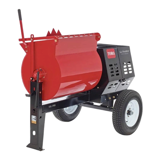
- Page 1 Form No. 3396-409 Rev A MMX-650E-S or MMX-850E-S Mortar Mixer Model No. 60212—Serial No. 315000001 and Up Model No. 60218—Serial No. 315000001 and Up Model No. 60219—Serial No. 315000001 and Up *3396-409* A Register at www.Toro.com. Original Instructions (EN)
- Page 2 You are responsible for operating the product properly and safely. Serial No. You may contact Toro directly at www.Toro.com for product safety and operation training materials, accessory information, help finding a dealer, or to register your product. This manual identifies potential hazards and has safety...
-
Page 3: Table Of Contents
Contents Safety Safety ................3 Improperly using or maintaining the machine can result Safe Operating Practices........... 3 in injury. To reduce the potential for injury, comply with Safety and Instructional Decals ......... 6 these safety instructions and always pay attention to the Setup ................ - Page 4 Towing – Hearing protection – Safety shoes Check with your local county or state towing safety regulations before towing the machine. – Long pants • In order to reduce the possibility of an accident while – Shirt with long sleeves that are tight at the wrists transporting the machine on public roads, make sure –...
- Page 5 Keep equipment in good condition. • To ensure optimum performance and continued safety certification of the machine, use only genuine Toro replacement parts and accessories. Replacement parts and accessories made by other manufacturers could be dangerous, and such use could void the product warranty..
-
Page 6: Safety And Instructional Decals
Safety and Instructional Decals Safety decals and instructions are easily visible to the operator and are located near any area of potential danger. Replace any decal that is damaged or lost. 125–8175 1. Read the Operator’s Manual for information on greasing the machine. -
Page 7: Setup
Setup Loose Parts Use the chart below to verify that all parts have been shipped. Procedure Description Qty. Dump handle Bolt Install the dump handle. Install the tow pole. Tow pole kit (sold separately) Safety chain (sold with optional tow pole kit) Install the safety chain. -
Page 8: Installing The Safety Chain
Installing the Tow Pole Installing the Safety Chain Parts needed for this procedure: Parts needed for this procedure: Tow pole kit (sold separately) Safety chain (sold with optional tow pole kit) Connecting link (sold with optional tow pole kit) Installing the Tow Pole to the Machine Installing the Safety Chain Note: The tow pole is purchased separately and includes the nut and bolt needed for installation. -
Page 9: Adjusting The Mixing Paddles
Installing the Connecting Links Product Overview Note: The connecting links are part of the optional tow pole kit. 1. Align the connecting link to the last link in one end of the safety chain (Figure 5D). 2. Insert the connecting link through the chain link until the connecting link snaps closed. -
Page 10: Controls
Controls Dump Handle Use the dump handle to rotate the drum to the dump position Become familiar with all the controls before you start the and to rotate the drum to the mix position (upright). motor and operate the machine. Clutch Lever The clutch lever is used to engage and disengage motor power to the paddles. -
Page 11: Specifications
Motor Controls The following motor controls are found on all models: G022280 Figure 11 1. Thermal-overload 3. Power cord protector reset button 2. O switch g020669 Figure 12 Motor O Switch 1. Motor O switch The O switch (Figure 12) allows the operator of the machine to start and stop the motor. -
Page 12: Operation
Checking the Tires and Wheels Operation Service Interval: Before each use or daily—Inspect the tires Important: Before operating, remove any debris from and wheels. the machine. Ensure that the area is clear of people. WARNING Preparing to Tow the Machine Failure to maintain correct tire pressure may result in tire failure and loss of control, resulting in Important: Ensure that your tow vehicle has towing... - Page 13 Hitching a Machine with a Stamped Ball the appropriate air pressure for the tires as installed at the factory. Coupler Important: Always check the information 1. Apply chassis grease to the socket of the coupler and on the actual tires for the correct air pressure the area of the clamp that contacts the ball.
- Page 14 Hitching a Machine with a Forged Ball Hitching a Machine with a Pintle Hitch Coupler Tow Pole 1. Remove the pin from the pintle hitch and open it 1. Apply removable thread-locking compound to the (Figure 19). threads of the coupler bolt to prevent the coupler handle from coming loose (Figure 18).
-
Page 15: Extending The Axle
Extending the Axle Note: Stow the excess chain inside the bottom of the front post by pushing it into the keyholes and latching the appropriate links into the keyhole slots. WARNING 2. Cross both lengths of chain under the tow pole. The machine is not stable when towing it with the axle in the narrow position. -
Page 16: Towing The Machine
4. Remove the bolts and nuts that secure the inner axle to WARNING the outer axle (Figure 23). Towing the machine with material in the drum increases the risk of a hitch malfunction and tire failure. In addition, material could bounce out of the drum and hit other vehicles and/or people. -
Page 17: Opening And Closing The Cowl
Opening and Closing the Cowl Powering the Machine Opening the Cowl Setting the Operating Voltage 1. At the side of the machine where the front cowl and The machine can operate with a 115 V or 230 V supply rear cowl meet, grasp the latch and pull it off from the voltage. - Page 18 Powering the Machine with a Portable plug. If it still does not fit, contact a qualified electrician to install the proper outlet. Do not change the machine plug or Generator extension-cord plug in any way. When using a portable generator as an electrical source, Note: The machine uses a twist-locking plug.
-
Page 19: Starting And Stopping The Motor
Using the Clutch Lever 4. On the side of the junction box for the motor, press the reset button for the thermal-overload protector Move the clutch lever clockwise to engage the clutch, and (Figure 25). counterclockwise to disengage the clutch (Figure 26). -
Page 20: Using The Drum
Mixing a Batch of Material in the Using the Drum Machine DANGER 1. Ensure that there is no old, loose material in the drum that can contaminate the batch of material; refer to Contact with the mixing paddles could cause Cleaning the Drum (page 21) Dumping the Drum damage or injury. - Page 21 5. Rotate the dump handle clockwise until the drum latch locks the drum in the upright position (Figure 28). 6. After discharging a batch of material, clean the drum; refer to Cleaning the Drum (page 21). Note: This step will clean the paddles and drum between batches and prevent dried material from forming, and contaminating the next batch of material.
-
Page 22: Maintenance
Maintenance Important: Before performing any maintenance procedures, first stop the motor, wait 5 minutes to allow all moving parts to come to a complete stop and cool, and unplug the power cord. Recommended Maintenance Schedule(s) Maintenance Service Maintenance Procedure Interval •... -
Page 23: Lubrication
Installing the Divider Plate Lubrication 1. Guide the divider plate into position against the front cowl. Lubricating the Bearings and Note: Start with the divider plate rotated slightly Seals counterclockwise, and then rotate it clockwise while lowering it into position. Service Interval: After each use—Lubricate the trunnions. -
Page 24: Lubricating The Motor Bearings
Lubricating the Drive Chain 2. Pump grease into each fitting as follows: • For the pillow-block bearings, pump 1 shot of Service Interval: Every 40 hours—Lubricate the drive chain grease into each fitting (Figure 31). with a non-sticky chain lubricant. •... -
Page 25: Belt Maintenance
Belt Maintenance A. Move the clutch lever to the O position; refer Controlling the Paddles (page 19). B. Loosen the nuts and bolts that secure the motor Servicing the Belts to the motor deck (Figure 35). Inspecting the Belts Service Interval: After the first 25 hours—Inspect the belts and adjust as necessary. -
Page 26: Replacing The Belts
G021601 Figure 37 1. Nut 2. Belt guide 4. Slip the forward belt forward and off the idler pulley (Figure 38). g020663 Figure 36 1. Motor pulley 5. Idler shaft 2. Idler pulley 6. Jam nut 3. Belt 7. Setscrew 4. - Page 27 4. Slip the rear belt over the idler pulley and align the belt B. Rotate the belt guide up or down until there is to the rear pulley groove. an air gap of 2.5 to 4.0 mm (3/32 to 5/32 inch) between the guide and each belt (Figure 39).
-
Page 28: Aligning The Pulleys
Aligning the Pulleys Drive Chain Maintenance 1. Remove the divider plate; refer to Removing the Divider Plate (page 22). Checking and Adjusting the 2. Place a straightedge across the face of the motor pulley Drive Chain and the idler pulley (Figure 40). -
Page 29: Paddle Maintenance
Paddle Maintenance Note: Over time, you may need to adjust the mixer paddles to account for wear. Adjusting the Paddles Aligning the Circumferential Drum Wipers 1. Rotate a paddle from the left row of paddles around G021602 the drum and locate at the interior of the drum the Figure 42 smallest distance between the drum and the wiper of 1. - Page 30 Aligning the End Paddle Wipers 1. Rotate the wiper and fixed paddle around the endplate of the drum and locate smallest distance between the drum and the wiper of the paddle. 2. Mark the inside of the endplate at the location that you determined in step 1.
-
Page 31: Cleaning
Aligning the Adjustable End Paddles Cleaning 1. Align the adjustable end paddle to the mark that you made in step Aligning the End Paddle Wipers Cleaning the Machine (page 30). 2. Loosen the carriage bolts and flanged locknuts that Regular cleaning and washing will increase the life span of secure the adjustable end paddle to the fixed paddle. -
Page 32: Storage
5. Paint all scratched or bare metal surfaces with paint from your Authorized Toro Dealer. 6. Store the machine in a clean, dry garage or storage area. 7. Cover the machine to protect it and keep it clean. -
Page 33: Troubleshooting
Troubleshooting Problem Possible Cause Corrective Action The electric motor does not start. 1. The connector for the machine is not 1. Plug the connector into a socket or plugged into a power source. an extension cord from an electrical source. 2. -
Page 34: Schematics
Schematics G021587 Electric Motor Schematic (Rev. A) - Page 35 Notes:...
- Page 36 Toro importer. If all other remedies fail, you may contact us at Toro Warranty Company. Australian Consumer Law: Australian customers will find details relating to the Australian Consumer Law either inside the box or at your local Toro Dealer.