Table of Contents
Advertisement
Quick Links
Advertisement
Table of Contents

Related Manuals for Toro MMX-658H-P


Summary of Contents for Toro MMX-658H-P
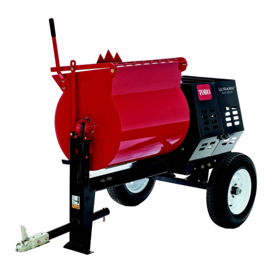
- Page 1 Form No. 3447-581 Rev A MMX-658H-P Mortar Mixer Model No. 60217—Serial No. 322000001 and Up Model No. 60221—Serial No. 322000001 and Up Model No. 60221HD—Serial No. 322000001 and Up *3447-581* Register at www.Toro.com. Original Instructions (EN)
- Page 2 NHTSA, 1200 New Jersey Avenue, SE West Building, additional information, contact an Authorized Service Washington, DC 20590. You can also obtain Dealer or Toro Customer Service and have the model other information about motor vehicle safety from and serial numbers of your product ready.
- Page 3 g249187 Figure 1 1. Model and serial number location Model No. Serial No. This manual identifies potential hazards and has safety messages identified by the safety-alert symbol (Figure 2), which signals a hazard that may cause serious injury or death if you do not follow the recommended precautions.
-
Page 4: Table Of Contents
Contents Paddle Maintenance ..........46 Adjusting the Paddles ........46 Cleaning .............. 48 Safety ............... 5 Cleaning the Machine ........48 Safe Operating Practices........5 Storage ..............48 Safety and Instructional Decals ......8 Troubleshooting ............50 Setup ...............11 1 Installing the Dump Handle ......11 2 Installing the Tow Pole ........ -
Page 5: Safety
Safety • Never let children or untrained people operate or service the equipment. Local regulations may restrict the age of the operator. Improper use or maintenance by the operator or • The owner/user can prevent and is responsible owner can result in injury. To reduce the potential for accidents or injuries to people or damage to for injury, comply with these safety instructions property. - Page 6 • • Do not tow the machine faster than 88 km/h (55 Extinguish all cigarettes, cigars, pipes, and other mph). sources of ignition. • • Use caution when backing up; use a spotter Use only an approved fuel container. outside the vehicle to guide you. •...
- Page 7 • Do not tamper with safety devices. • Chock the tires when storing the machine. • Keep all fasteners and hose clamps securely tightened and all equipment in good condition. • Use only genuine Toro replacement parts.
-
Page 8: Safety And Instructional Decals
Safety and Instructional Decals Safety decals and instructions are easily visible to the operator and are located near any area of potential danger. Replace any decal that is damaged or missing. decal125-8175 125-8175 1. Read the Operator’s Manual for information on greasing the machine. - Page 9 decal133-8062 133-8062 decal130-8322 130-8322 1. Use fuel with an alcohol 3. Do not use fuel with an content by volume under alcohol content greater 10% only. than 10% by volume. 2. Read the Operator's Manual for more information on fuel. decal137-7483 137-7483...
- Page 10 decal137-7491 137-7491 1. Read the Operator’s Manual.
-
Page 11: Setup
Setup Loose Parts Use the chart below to verify that all parts have been shipped. Procedure Description Qty. Dump handle Carriage bolt Install the dump handle. Install the tow pole (side-dump models Tow pole kit (sold separately) only). Safety chain (included with the tow pole kit) Install the safety chain. -
Page 12: Installing The Tow Pole
Thread the nut onto the bolt and tighten them until they are tight against the frame fitting (Figure Note: If the self-locking nylon insert in the Installing the Tow Pole locknut wears with use, replace the nut with a new Grade 5 or Grade 8 locknut. Parts needed for this procedure: Tow pole kit (sold separately) Tow Pole Specifications... -
Page 13: Adjusting The Mixing Paddles
Product Overview Adjusting the Mixing Paddles No Parts Required Procedure Adjust the paddle blades to be as close as possible to the inner walls of the drum; refer to Adjusting the Paddles (page 46). g232184 Figure 6 Right side 1. Rear cowl 7. -
Page 14: Controls
Controls Dump Handle Use the dump handle to rotate the drum to the dump Become familiar with all the controls before you start position and to rotate the drum to the mix position the engine and operate the machine. (upright). Clutch Lever Use the clutch lever to engage and disengage the paddles. -
Page 15: Engine Controls
Engine Controls Fuel Valve The fuel valve (Figure 12 Figure 13) is located underneath the choke lever. Move the lever for the fuel valve to the O position before attempting to start the engine. When you have finished mixing, shut off the engine and move the fuel-valve lever to the O position. - Page 16 the engine is running, move the choke lever to the position. Do not use the choke if the engine is already warmed up or if the air temperature is high. Throttle Lever The throttle lever (Figure 12 Figure 11) controls the speed (rpm) of the engine.
-
Page 17: Specifications
Specifications Note: Specifications and design are subject to change without notice. Machine Specifications Model 60217, 60217C 60221, 60221C 60221HD Batch Capacity 0.17 m (6.0 ft 0.23 m (8.0 ft 0.23 m (8.0 ft Total Volume 0.19 m (6.7 ft 0.24 m (8.6 ft 0.24 m (8.6 ft... - Page 18 Hitching a Stamped-Ball Coupler vehicle is compatible with the electrical connector of the machine. The machine uses a standard Apply chassis grease to the socket of the coupler 4-pin, flat plug. If your tow vehicle has a different and the area of the clamp that contacts the ball. type of plug, obtain an adapter from an automotive parts store.
- Page 19 Connecting the Safety Chains to the Tow Vehicle Pull the safety chain through the slots in the keyholes, so that the lengths on each side are equal. Cross both lengths of chain under the tow pole. Note: Crossing the chains decreases the chances of the front of the machine dropping to the ground if the hitch does not hold the connection.
-
Page 20: Adjusting The Axle Width
The corresponding turn-signal lights of the machine should illuminate. Adjusting the Axle Width Models with Adjustable Axles Only If your model is equipped with an adjustable axle (Figure 23), you can adjust the axle to the narrow position to move the machine through a narrow access point, such as the gate of a fence or the doorway of a building. -
Page 21: Preparing To Use The Machine
Ensure that all guards and paddles are in place and in good condition. Perform all daily maintenance procedures prescribed in Maintenance (page 27). Chock the front and back of the tires to prevent the machine from moving. Move the drum to the upright position and lock it. Opening the Cowl g029390 Figure 22... -
Page 22: Closing The Cowl
Closing the Cowl DANGER In certain conditions during fueling, static electricity can be released, causing a spark that can ignite the fuel vapors. A fire or explosion from fuel can burn you and others and can damage property. • Always place fuel containers on the ground away from your vehicle before filling. -
Page 23: Performing Daily Maintenance
Capacity 7.0 L (1.85 US gallons) for models 60217, 60217C, 60221, 60221C Capacity 5.3 L (1.40 US gallons) for model 30221HD Type Unleaded gasoline MTBE Less than 15% by volumne (methyl tertiary butyl ether) Do not add to the fuel Filling the Fuel Tank Park the machine on a level surface, shut off the engine, and allow the engine to cool. -
Page 24: Shutting Off The Engine
g019747 Figure 30 Model 60221HD shown After the engine starts, gradually move the choke lever back to the O position. If the engine stalls or hesitates, move the choke back to the O position again until the engine warms g019815 Figure 28 up. - Page 25 DANGER This machine is capable of amputating hands. • Stay in the operator’s position while the machine is running. • Keep all bystanders away from the machine. • Stop the machine immediately if any people or animals enter the work area. •...
-
Page 26: Dumping The Material
Allow the paddles to mix the material until the With both hands on the dump handle, rotate it ingredients have a uniform appearance. counterclockwise to discharge the contents of the drum (Figure 33). Note: If needed, add water or plaster, cement, or other binding material until the consistency Note: Allow the machine to completely... -
Page 27: Maintenance
Maintenance WARNING Failure to properly maintain the machine could result in premature failure of machine systems, causing possible harm to you or bystanders. Keep the machine well maintained and in good working order as indicated in these instructions. Important: Refer to your engine operator's manual for additional maintenance procedures. Recommended Maintenance Schedule(s) Maintenance Service Maintenance Procedure... -
Page 28: Pre-Maintenance Procedures
Pre-Maintenance Procedures Preparing the Machine for Maintenance Shut off the engine and allow it to cool completely. g232217 Park the machine on a level surface. Figure 35 Remove the machine from the tow vehicle. Secure the machine from movement. To remove the divider plate, lift it upward and tilt it back so that it clears various components. -
Page 29: Lubrication
Lubrication Lubricating the Bearings, Seals, and Gears Service Interval: After each use—Lubricate the trunnions. Monthly—Lubricate the pillow-block bearings. Every 100 hours—Lubricate all the gear teeth around the paddle-drive gear and pinion gear. g250569 Note: The pillow-block bearings are inside the cowl—remove the divider plate (if equipped) to access them;... -
Page 30: Engine Maintenance
Engine Maintenance Servicing the Air Cleaner Service Interval: Before each use or daily—Inspect the air-cleaner elements. Every 50 hours—Clean the air-cleaner elements. Clean them more frequently in dusty operating conditions. Every 300 hours/Yearly (whichever comes first)—Replace the paper air-cleaner element. Replace it more frequently in dusty operating conditions. -
Page 31: Servicing The Engine Oil
Securely install the cover with the nut. Servicing the Engine Oil Engine-Oil Specifications Toro Premium Engine Oil is available from your Authorized Toro Dealer. Important: Use 4-cycle engine oil that meets or exceeds the requirements for API service category SJ, SL, SM, or higher. - Page 32 Checking the Engine-Oil Level Changing the Engine Oil Service Interval: After the first 25 hours Service Interval: Before each use or daily Every 100 hours Park the machine on a level surface and shut off the engine. WARNING Allow the engine to cool. Oil may be hot after the engine has been run, Disconnect the wire from the spark plug;...
-
Page 33: Servicing The Spark Plug
Removing the Spark Plug Park the machine on a level surface and shut off the engine. Ensure that the machine surfaces are cool. Pull the spark-plug wire off the terminal of the spark plug (Figure 44). g028981 Figure 43 1. Oil-fill hole 3. -
Page 34: Cleaning The Spark Arrester
If you see light brown or gray on the insulator, Toro Service Dealer. the engine is operating properly. A black coating on Genuine Toro spark arresters are approved by the the insulator usually means that the air cleaner is dirty. USDA Forestry Service. -
Page 35: Removing And Installing The Engine
(page 43). protector (Figure 47). Using a spring-removal tool (Toro Part No. Remove the screws (4 mm) from the spark 92-5771), remove the spring from the anchor arrester, and remove the spark arrester from the bracket on the engine deck (Figure 49). - Page 36 (Figure removed in step Removing the Engine (page 35). Using a spring-removal tool (Toro Part No. 92-5771), install the tension spring to the anchor g020120 Figure 50 bracket on the engine deck (Figure 49).
-
Page 37: Fuel System Maintenance
Fuel System Wipe the O-ring with a clean, dry cloth. Install the fuel filter in the bottom of the Maintenance carburetor (Figure 52). Align the O-ring in to the groove in the sediment Cleaning the Fuel-Sediment cup and install the sediment cup to the fuel-valve housing. -
Page 38: Electrical System Maintenance
Electrical System Maintenance Servicing the Light Bulbs For Models 60217C, 60221C, 60221C Replacing the Rear-Facing Side Bulbs g020830 Figure 56 Note: The left rear-facing bulb also illuminates license plate. Remove the lens (Figure 56). Use a screwdriver to remove the 4 screws from Pull the bulb out of the socket (Figure 56). -
Page 39: Drive System Maintenance
Drive System Maintenance Tire Air Pressure The following table shows the appropriate air pressure for the tires as installed at the factory. g020836 Figure 58 Important: Always check the information on the actual tires for the correct air pressure 1. Example of tire wear caused by underinflation requirement. -
Page 40: Servicing The Reduction Case
Servicing the Reduction Align a rag below the oil-level port in the side of the reduction case. Case Remove the oil-level-check bolt and washer from the oil-level port (Figure 61). Model 60221HD Only • If the oil level is below the threads in the Important: If the oil level in the reduction case oil-level port, add oil as follows:... - Page 41 Changing the Reduction-Case Oil Service Interval: After the first 20 hours—Change the reduction-case oil (Model 60221HD only). Every 100 hours/Every 6 months (whichever comes first)—Change the reduction-case oil (Model 60221HD only). Park the machine on a level surface and shut off the engine.
-
Page 42: Belt Maintenance
Belt Maintenance Inspecting the Belts Service Interval: After the first 25 hours—Inspect the belts and adjust as necessary (belt-drive models only). Every 40 hours—Inspect the belts and adjust as necessary (belt-drive models only). Park the machine on a level surface and shut off the engine. -
Page 43: Replacing The Belts
Remove the divider plate; refer to Removing the Divider Plate (page 28). Remove the bolt that secures the belt guide to the engine, and remove the belt guide (Figure 67). g020010 Figure 67 g020009 Figure 66 1. Bolt 2. Belt guide 1. - Page 44 Disconnect the wire from the spark plug; refer to Disconnecting the Spark-Plug Wire (page 28). Ensure that the clutch lever is in the O position. Align the rear belt to the rear groove in the engine pulley. Note: Do not align the rear belt to the idler pulley.
-
Page 45: Aligning The Pulleys
Aligning the Pulleys Shut off the engine. Check the air gap between the belt guide Park the machine on a level surface and shut and the belts. off the engine. Note: If the air gap is larger than 4.0 mm Allow the machine to cool. -
Page 46: Paddle Maintenance
Paddle Maintenance Adjusting the Paddles Important: Complete the Preparing the Machine for Maintenance (page 28) before adjusting any of the paddles. Note: Over time, you may need to adjust the mixer paddles to account for wear. g029188 Figure 72 Aligning the Circumferential-Drum 1. - Page 47 Aligning the End-Paddle Wipers Aligning the Adjustable-End Paddles Rotate the wiper and fixed paddle around the end plate of the drum and locate smallest Align the adjustable-end paddle to the mark that distance between the drum and the wiper of the you made in step Aligning the End-Paddle paddle.
-
Page 48: Storage
Cleaning Storage For storage over 30 days, prepare the machine as Cleaning the Machine follows: Remove dirt and grime from the external parts of Regular cleaning and washing with mild detergent and the entire machine, especially the engine. Clean water increases the life span of the machine. Clean dirt and debris from the outside of the engine the machine after each use before the dirt hardens. - Page 49 Note: Do not install the wire on the spark plug. Grease the machine; refer to Lubricating the Bearings, Seals, and Gears (page 29). Check and tighten all bolts, nuts, and screws. Repair or replace any part that is damaged. Paint all scratched or bare metal surfaces with paint available from your Authorized Service Dealer.
-
Page 50: Troubleshooting
Troubleshooting Problem Possible Cause Corrective Action The engine does not start. 1. The fuel-valve lever is in the O 1. Move the fuel-valve lever to the O position. position. 2. The choke is closed 2. Open the choke when starting a hot engine. - Page 51 While the exposure from Toro products may be negligible or well within the “no significant risk” range, out of an abundance of caution, Toro has elected to provide the Prop 65 warnings. Moreover, if Toro does not provide these warnings, it could be sued by the State of California or by private parties seeking to enforce Prop 65 and subject to substantial penalties.