Table of Contents
Advertisement
Quick Links
Advertisement
Table of Contents

Related Manuals for Toro 60213 60216


Summary of Contents for Toro 60213 60216
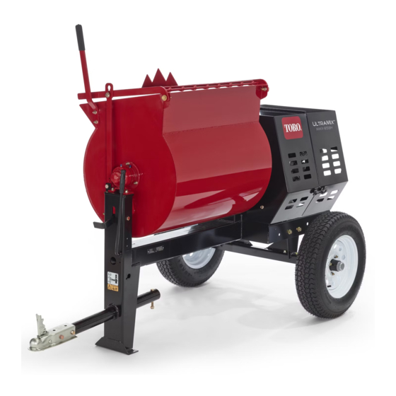
- Page 1 Form No. 3395-946 Rev C MMX-655H-S, MMX-658H-S, and MMX-858H-S Mortar Mixer Model No. 60213—Serial No. 315000001 and Up Model No. 60216—Serial No. 315000001 and Up Model No. 60220—Serial No. 315000001 and Up *3395-946* C Register at www.Toro.com. Original Instructions (EN)
- Page 2 Section 4442 or 4443 to use or operate the engine on additional information, contact an Authorized Service any forest-covered, brush-covered, or grass-covered Dealer or Toro Customer Service and have the model land unless the engine is equipped with a spark and serial numbers of your product ready.
-
Page 3: Table Of Contents
This manual uses 2 words to highlight information. Belt Maintenance ..........42 Important calls attention to special mechanical Inspecting the Belts .......... 42 information and Note emphasizes general information Adjusting the Belt Tension......... 42 worthy of special attention. Replacing the Belts........... 44 Aligning the Pulleys .......... -
Page 4: Safety
Safety • Read and understand the contents of this Operator’s Manual before you start the engine. Ensure that everyone using this product knows Improper use or maintenance by the operator or how to use it and understands the warnings. owner can result in injury. To reduce the potential •... - Page 5 • Do not carry any material in the machine when – Ensure that the lug nuts are tight and torqued towing. properly. • Avoid sudden stops and starts. This can cause – Ensure that the machine is properly secured. skidding or jackknifing. Smooth, gradual starts and stops improves towing.
- Page 6 • Do not tamper with safety devices. • Chock the tires when storing the machine. • Keep all fasteners and hose clamps securely tightened and all equipment in good condition. • Use only genuine Toro replacement parts.
-
Page 7: Safety And Instructional Decals
Safety and Instructional Decals Safety decals and instructions are easily visible to the operator and are located near any area of potential danger. Replace any decal that is damaged or missing. decal125-8175 125-8175 1. Read the Operator’s Manual for information on greasing the machine. - Page 8 decal130-8322 130-8322 1. Use fuel with an alcohol 3. Do not use fuel with an content by volume under alcohol content greater 10% only. than 10% by volume. 2. Read the Operator's Manual for more information on fuel. decal133-5619 133-5619...
-
Page 9: Setup
Setup Loose Parts Use the chart below to verify that all parts have been shipped. Procedure Description Qty. Dump handle Carriage bolt Install the dump handle. Install the tow pole (side-dump models Tow pole kit (sold separately) only). Safety chain (included with the tow pole kit) Install the safety chain. -
Page 10: Installing The Safety Chain
Thread the nut onto the bolt and tighten them until they are tight against the frame fitting (Figure Note: If the self-locking nylon insert in the Installing the Tow Pole locknut wears with use, replace the nut with a new Grade 5 or Grade 8 locknut. Parts needed for this procedure: Tow pole kit (sold separately) Tow Pole Specifications... -
Page 11: Adjusting The Mixing Paddles
Adjusting the Mixing Paddles No Parts Required Procedure If the mixing paddles and wipers need adjustment, adjust the paddles and wipers; refer to Adjusting the Paddles (page 46). -
Page 12: Product Overview
Product Overview g019875 Figure 7 1. Clutch lever Drum Latch g028571 Figure 6 Use the drum latch to secure the drum to the mix Right side position (upright) for mixing operations and when transporting the machine. 1. Rear cowl 7. Clutch lever 13. -
Page 13: Engine Controls
Dump Handle Engine Controls Use the dump handle to rotate the drum to the dump position and to rotate the drum to the mix position (upright). g019744 Figure 10 1. Recoil-start handle 5. Fuel cap 2. Fuel valve 6. Oil dipstick 3. - Page 14 Choke Lever Use the choke lever (Figure 11) to start a cold engine. Before pulling the recoil-start handle, move the choke lever to the C position. Once the engine is LOSED running, move the choke lever to the O position. Do not use the choke if the engine is already warmed up or if the air temperature is high.
-
Page 15: Specifications
Specifications Note: Specifications and design are subject to change without notice. Machine Specifications Model 60217, 60217C 60221, 60221C 60221HD Batch Capacity 0.17 m (6.0 ft 0.23 m (8.0 ft 0.23 m (8.0 ft Total Volume 0.19 m (6.7 ft 0.24 m (8.6 ft 0.24 m (8.6 ft... -
Page 16: Operation
Towing the Machine Operation Before towing the machine, read all the information and perform all the applicable procedures to in this Think Safety First section to ensure safe and proper towing. Carefully read all safety instructions and symbols in WARNING this manual, on the product decals, and other media supplied with the product. - Page 17 Preparing the Machine for Towing Shut off the engine and fuel valve. Empty the drum. Position the drum in the mix position (upright) and lock it. Close the engine cowl and secure the cowl latches (Figure 14). g022324 Figure 14 If you have adjusted the axle to the narrow position (if equipped on your model), extend the axle;...
- Page 18 Connecting the Safety Chains to the Tow Vehicle Pull the safety chain through the slots in the keyholes, so that the lengths on each side are equal. Cross both lengths of chain under the tow pole. Note: Crossing the chains decreases the chances of the front of the machine dropping to the ground if the hitch does not hold the connection.
-
Page 19: Adjusting The Axle Width
The corresponding turn-signal lights of the machine should illuminate. Adjusting the Axle Width Models with Adjustable Axles Only If your model is equipped with an adjustable axle (Figure 22), you can adjust the axle to the narrow position to move the machine through a narrow access point, such as the gate of a fence or the doorway of a building. -
Page 20: Preparing To Use The Machine
Preparing to Use the Machine Park the machine on a level surface and disconnect the machine from the tow vehicle. Ensure that all guards and paddles are in place and in good condition. Perform all daily maintenance procedures prescribed in Maintenance (page 27). -
Page 21: Opening And Closing The Cowl
Opening and Closing the Closing the Cowl Cowl Opening the Cowl g035135 Figure 25 Adding Fuel g035134 Figure 24 DANGER In certain conditions, fuel is extremely flammable and highly explosive. A fire or explosion from fuel can burn you and others and can damage property. - Page 22 • Do not store fuel either in the fuel tank or in fuel DANGER containers over the winter unless you use a fuel In certain conditions during fueling, static stabilizer. electricity can be released, causing a spark • Do not add oil to gasoline. that can ignite the fuel vapors.
-
Page 23: Performing Daily Maintenance
g019815 Figure 28 1. Choke lever 3. Throttle lever 2. Fuel valve g020679 Figure 27 Move the choke lever to the O position (Figure 1. Maximum fuel level 28). Note: A warm or hot engine may not require Install the fuel cap securely (Figure 26). -
Page 24: Shutting Off The Engine
Mixing the Material DANGER Eye and skin contact with concrete materials and breathing the dust involved is hazardous to your health. • Ensure that there is adequate air ventilation. • Wear a dust mask to prevent inhalation of dust while using the machine; refer to Safe Operating Practices (page g019747... -
Page 25: Dumping The Material
Allow the paddles to mix the material until the ingredients have a uniform appearance. Note: If needed, add water or plaster, cement, or other binding material until the consistency of the batch is correct. Dumping the Material DANGER Contact with the mixing paddles could cause damage or injury. -
Page 26: Cleaning The Drum
With both hands on the dump handle, rotate it counterclockwise to discharge the contents of the drum (Figure 33). Note: Allow the machine to completely discharge the contents of the drum. Rotate the dump handle clockwise until the drum latch locks the drum in the upright position (Figure 33). -
Page 27: Maintenance
Maintenance WARNING Failure to properly maintain the machine could result in premature failure of machine systems causing possible harm to you or bystanders. Keep the machine well maintained and in good working order as indicated in these instructions. Important: Refer to your engine operator's manual for additional maintenance procedures. Recommended Maintenance Schedule(s) Maintenance Service Maintenance Procedure... -
Page 28: Pre-Maintenance Procedures
Pre-Maintenance Procedures Preparing the Machine for Maintenance Shut off the engine and allow it to cool completely. Park the machine on a level surface. g020752 Figure 35 Remove the machine from the tow vehicle. Secure the machine from movement. To remove the divider plate, lift it upward and tilt Disconnect the spark-plug wire. -
Page 29: Lubrication
Lubrication Lubricating the Bearings and Seals Service Interval: After each use—Lubricate the trunnions. Monthly—Lubricate the pillow-block bearings. Note: The pillow-block bearings are inside the cowl—remove the divider plate if equipped) to access g020684 them; refer to Removing the Divider Plate (page 28). -
Page 30: Greasing The Wheel Bearings
Greasing the Wheel Greasing the Wheel Bearings Bearings Service Interval: Yearly Remove the seal and bearings from the hub. Removing the Wheels and Hub Assembly Support the machine with jack stands. Remove the lug nuts securing the wheel to the (Figure 38). -
Page 31: Engine Maintenance
Engine Maintenance Torque the spindle nut to 27 N∙m (20 ft-lb) while rotating the hub. Back the nut off 1 turn, and torque the spindle nut to 9 N∙m (7 ft-lb). Servicing the Air Cleaner Install the nut retainer and check the alignment of the slot in the retainer and the hole in the Service Interval: Before each use or daily—Inspect spindle for the cotter pin... -
Page 32: Servicing The Engine Oil
Securely install the cover with the nut. Servicing the Engine Oil Engine-Oil Specifications Toro Premium Engine Oil is available from your Authorized Toro Dealer. Important: Use 4-cycle engine oil that meets or exceeds the requirements for API service category SJ, SL, SM, or higher. - Page 33 Checking the Engine-Oil Level WARNING Oil may be hot after the engine has been run, Service Interval: Before each use or daily and contact with hot oil can cause severe Park the machine on a level surface and shut personal injury. off the engine.
-
Page 34: Servicing The Spark Plug
g028981 g014506 Figure 46 Figure 47 1. Oil-fill hole 3. Oil-level upper limit 1. Spark plug 2. Wire 2. Dipstick 4. Oil-level lower limit Clean around the spark plug. Replace and secure the dipstick. Rotate the spark plug counterclockwise using Wipe up any spilled oil. - Page 35 Installing the Spark Plug Important: Ensure that the gap between the side and center electrodes is correct before installing the spark plug. Thread the spark plug clockwise into the spark-plug hole by hand. Note: Avoid cross-threading the spark plug with g206628 Figure 49 the threads of the spark-plug hole.
-
Page 36: Cleaning The Spark Arrester
A spark arrester is available as an option. If Remove the screws (4 mm) from the spark you require a spark arrester, contact your Authorized arrester, and remove the spark arrester from the Service Dealer. Genuine Toro spark arresters are muffler (Figure 50). - Page 37 Note: Using a spring-removal tool (Toro Part No. Do not remove the forward hinge bracket. 92-5771), remove the spring from the anchor bracket on the engine deck (Figure 52). Note: Leave the other end of the spring attached to the frame of the machine.
-
Page 38: Fuel System Maintenance
Allow the engine to cool. (page 36). Disconnect the wire from the spark plug; refer to Using a spring-removal tool (Toro Part No. Disconnecting the Spark-Plug Wire (page 28). 92-5771), install the tension spring to the anchor Move the lever of the fuel valve to the O... -
Page 39: Draining The Fuel Tank
Drive System Align the O-ring in to the groove in the sediment cup and install the sediment cup to the fuel-valve Maintenance housing. Move the lever of the fuel valve to the O position (all the way to the right) and check for Tire Air Pressure leaks. -
Page 40: Torquing The Wheel Lug Nuts
Servicing the Reduction Case Important: If the oil level in the reduction case is too low or too high and you run the engine, you may damage the engine or the reduction case. This type of damage is not covered by the warranty. - Page 41 Remove the oil-level-check bolt and washer from the oil-level port (Figure 61). • If the oil level is below the threads in the oil-level port, add oil as follows: Remove the filler bolt and washer from the filler port on the top of the reduction case (Figure 61).
-
Page 42: Belt Maintenance
Belt Maintenance Install the filler bolt and washer to the filler port of the reduction case and tighten the filler bolt (Figure 62). Inspecting the Belts Install the engine; refer to Installing the Engine (page 38). Service Interval: After the first 25 hours—Inspect the belts and adjust as necessary (belt-drive models only). - Page 43 g019976 Figure 64 g020009 1. Engine deck 3. Clutch air gap: 2.5 to 6.5 Figure 66 mm (3/32 to 1/4 inch) 1. Engine pulley 5. Idler shaft 2. Clutch roller 2. Idler pulley 6. Jam nut 3. Reduction case (engine) 7.
-
Page 44: Replacing The Belts
Replacing the Belts Service Interval: Every 2 years (belt-drive models only). Removing the Belts Park the machine on a level surface and shut off the engine. Allow the machine to cool. Disconnect the wire from the spark plug; refer to Disconnecting the Spark-Plug Wire (page 28). -
Page 45: Aligning The Pulleys
Adjusting the Belt Guide Tighten the bolt that secures the belt guide to the engine (Figure 69). Note: To access the belt guide, remove the divider Check the clutch operation; refer to plate; refer to Removing the Divider Plate (page 28). -
Page 46: Paddle Maintenance
Paddle Maintenance Adjusting the Paddles Important: Complete the Preparing the Machine for Maintenance (page 28) before adjusting any of the paddles. Note: Over time, you may need to adjust the mixer paddles to account for wear. Aligning the Circumferential-Drum Wipers Rotate a paddle from the left row of paddles g020015 Figure 70... - Page 47 Aligning the End-Paddle Wipers Rotate the wiper and fixed paddle around the end plate of the drum and locate smallest distance between the drum and the wiper of the paddle. Mark the inside of the end plate at the location that you determined in step 1.
-
Page 48: Cleaning
Aligning the Adjustable-End Cleaning Paddles Align the adjustable-end paddle to the mark that Cleaning the Machine you made in step Aligning the End-Paddle Wipers (page 47). Regular cleaning and washing with mild detergent and water increases the life span of the machine. Clean Loosen the carriage bolts and flanged locknuts the machine after each use before the dirt hardens. -
Page 49: Storage
Storage Note: Do not install the wire on the spark plug. Grease the machine; refer to Lubricating the For storage over 30 days, prepare the machine as Bearings and Seals (page 29). follows: Check and tighten all bolts, nuts, and screws. Remove dirt and grime from the external parts of Repair or replace any part that is damaged. -
Page 50: Troubleshooting
Troubleshooting Problem Possible Cause Corrective Action The engine does not start. 1. The fuel-valve lever is in the O 1. Move the fuel-valve lever to the O position. position. 2. The choke is closed 2. Open the choke when starting a hot engine. - Page 51 While the exposure from Toro products may be negligible or well within the “no significant risk” range, out of an abundance of caution, Toro has elected to provide the Prop 65 warnings. Moreover, if Toro does not provide these warnings, it could be sued by the State of California or by private parties seeking to enforce Prop 65 and subject to substantial penalties.
- Page 52 Toro importer. If all other remedies fail, you may contact us at Toro Warranty Company. Australian Consumer Law: Australian customers will find details relating to the Australian Consumer Law either inside the box or at your local Toro Dealer.