ZyXEL Communications IES-1248-51 User Manual
Adsl2+ ip dslam
Hide thumbs
Also See for IES-1248-51:
- User manual (385 pages) ,
- Specifications (2 pages) ,
- Specifications (4 pages)

Related Manuals for ZyXEL Communications IES-1248-51


Summary of Contents for ZyXEL Communications IES-1248-51
- Page 1 IES-1248-51/51A/53 ADSL2+ IP DSLAM User’s Guide Version 3.52 (ABQ.0), (ABR.0) Edition 1 7/2006...
- Page 2 IES-1248-51/51A/53 User’s Guide...
-
Page 3: Copyright
Published by ZyXEL Communications Corporation. All rights reserved. Disclaimer ZyXEL does not assume any liability arising out of the application or use of any products, or software described herein. Neither does it convey any license under its patent rights nor the patent rights of others. -
Page 4: Certifications
Cet appareil numérique de la classe A est conforme à la norme NMB-003 du Canada. Viewing Certifications 1 Go to http://www.zyxel.com. 2 Select your product from the drop-down list box on the ZyXEL home page to go to that product's page. 3 Select the certification you wish to view from this page. -
Page 5: Safety Warnings
IES-1248-51/51A/53 User’s Guide Safety Warnings For your safety, be sure to read and follow all warning notices and instructions. • Do NOT use this product near water, for example, in a wet basement or near a swimming pool. • Do NOT expose your device to dampness, dust or corrosive liquids. •... - Page 6 IES-1248-51/51A/53 User’s Guide This product is recyclable. Dispose of it properly. Safety Warnings...
-
Page 7: Zyxel Limited Warranty
Any returned products without proof of purchase or those with an out-dated warranty will be repaired or replaced (at the discretion of ZyXEL) and the customer will be billed for parts and labor. All repaired or replaced products will be shipped by ZyXEL to the corresponding return address, Postage Paid. -
Page 8: Customer Support
• Brief description of the problem and the steps you took to solve it. METHOD SUPPORT E-MAIL TELEPHONE WEB SITE REGULAR MAIL SALES E-MAIL FTP SITE LOCATION support@zyxel.com.tw +886-3-578-3942 www.zyxel.com ZyXEL Communications Corp. CORPORATE www.europe.zyxel.com 6 Innovation Road II HEADQUARTERS Science Park sales@zyxel.com.tw +886-3-578-2439 ftp.zyxel.com Hsinchu 300 (WORLDWIDE) Taiwan ftp.europe.zyxel.com... - Page 9 METHOD SUPPORT E-MAIL TELEPHONE WEB SITE REGULAR MAIL SALES E-MAIL FTP SITE LOCATION support@zyxel.no +47-22-80-61-80 www.zyxel.no ZyXEL Communications A/S Nils Hansens vei 13 NORWAY sales@zyxel.no +47-22-80-61-81 0667 Oslo Norway info@pl.zyxel.com +48 (22) 333 8250 www.pl.zyxel.com ZyXEL Communications ul. Okrzei 1A...
- Page 10 IES-1248-51/51A/53 User’s Guide Customer Support...
-
Page 11: Table Of Contents
IES-1248-51/51A/53 User’s Guide Table of Contents Copyright ........................3 Certifications ......................4 Safety Warnings ....................... 5 ZyXEL Limited Warranty..................7 Customer Support....................8 Table of Contents ....................11 List of Figures ......................27 List of Tables ......................35 Preface ........................39 Chapter 1 Getting to Know the IES-1248 ................ - Page 12 IES-1248-51/51A/53 User’s Guide 3.2.1 Ethernet Default Settings ................55 3.3 SFP Mini GBIC Slots ..................55 3.3.1 Transceiver Installation ................56 3.3.2 Transceiver Removal ................57 3.4 Console Port Connection ...................58 3.5 ALARM Connections ..................58 3.6 ADSL Connections .....................59 Chapter 4 MDF Connections....................61 4.1 MDF Connections Overview ................61 4.2 MDF (Main Distribution Frame) ................61 4.3 Telco-50 Cables ....................62...
- Page 13 IES-1248-51/51A/53 User’s Guide 7.6 Saving Your Configuration ..................78 7.7 Logging Out of the Web Configurator ..............78 Chapter 8 Initial Configuration ....................81 8.1 Initial Configuration Overview ................81 8.2 Initial Configuration ....................81 Chapter 9 Home and Port Statistics Screens................ 87 9.1 Home Screen .....................87 9.1.1 Ethernet Port Statistics Screen ..............88 9.1.2 ADSL Port Statistics Screen ..............91 9.1.3 RMON Statistics Screen ................93...
- Page 14 IES-1248-51/51A/53 User’s Guide Chapter 14 IP Setup......................... 115 Chapter 15 ENET Port Setup ....................117 Chapter 16 xDSL Port Setup....................119 16.1 ADSL Standards Overview ................119 16.2 Downstream and Upstream ................119 16.3 Profiles ......................120 16.4 Interleave Delay .....................120 16.4.1 Fast Mode .....................120 16.5 Configured Versus Actual Rate ..............120 16.6 Default Settings ....................121 16.7 xDSL Port Setup Screen ................121...
- Page 15 IES-1248-51/51A/53 User’s Guide 17.5 VC Profile Screen ...................143 17.6 Alarm Profile Screen ..................145 17.7 IGMP Filtering ....................147 17.8 IGMP Filter Profile Screen ................148 Chapter 18 xDSL Line Data ..................... 151 18.1 xDSL Line Rate Info Screen ................151 18.2 xDSL Performance Screen ................153 18.3 xDSL Line Data Screen ..................155 Chapter 19 VLAN ........................
- Page 16 IES-1248-51/51A/53 User’s Guide 22.2 MVLAN Status Screen ...................177 22.3 MVLAN Setup Screen ..................178 22.4 MVLAN Group Screen ...................180 Chapter 23 Filtering ......................... 183 23.1 Packet Filter Screen ..................183 Chapter 24 MAC Filter ......................185 24.1 MAC Filter Introduction ..................185 24.2 MAC Filter Screen ..................185 Chapter 25 Spanning Tree Protocol ..................
- Page 17 IES-1248-51/51A/53 User’s Guide 29.3 DHCP Snoop Status Screen ................204 29.4 DHCP Counter Screen ...................205 Chapter 30 2684 Routed Mode ....................207 30.1 2684 Routed Mode ..................207 30.1.1 2684 Routed Mode Example ..............207 30.2 2684 Routed PVC Screen ................208 30.3 2684 Routed Domain Screen .................210 30.4 RPVC Arp Proxy Screen ................211 30.5 2684 Routed Gateway Screen ...............212 Chapter 31...
- Page 18 IES-1248-51/51A/53 User’s Guide Chapter 36 Syslog ........................235 36.1 Syslog ......................235 36.2 SysLog Screen ....................235 Chapter 37 Access Control..................... 237 37.1 Access Control Screen ...................237 37.2 Access Control Overview ................237 37.3 SNMP ......................237 37.3.1 Supported MIBs ..................239 37.3.2 SNMP Traps ..................239 37.4 SNMP Screen ....................241 37.5 Service Access Control Screen ..............242 37.6 Remote Management Screen ................243...
- Page 19 IES-1248-51/51A/53 User’s Guide 41.3 LDM Test Parameters ..................263 41.4 ToneDiag Parameters ..................264 Chapter 42 MAC Table ......................265 42.1 Introduction to MAC Table ................265 42.2 MAC Table Screen ..................266 Chapter 43 ARP Table......................267 43.1 Introduction to ARP Table ................267 43.1.1 How ARP Works ...................267 43.2 ARP Table Screen ..................267 Chapter 44...
- Page 20 IES-1248-51/51A/53 User’s Guide 46.5 Alarm Port Set Command ................299 46.6 Alarm Tablelist Command ................300 46.7 Log Format .....................301 46.8 Alarm History Show Command ..............301 46.9 Alarm History Clear Command ..............302 46.10 Alarm XEdit Command .................302 46.11 Alarm Cutoff Command ................303 46.12 Alarm Clear Command .................303 Chapter 47 DHCP Commands ....................
- Page 21 IES-1248-51/51A/53 User’s Guide 48.4.2 VLAN PVID Command .................314 48.4.3 VLAN Priority Command ...............315 48.4.4 VLAN Set Command ................315 48.4.4.1 Modify a Static VLAN Table Example ..........316 48.4.4.2 Forwarding Process Example .............316 48.4.5 VLAN Frame Type Command ...............317 48.4.6 VLAN CPU Show Command ..............317 48.4.7 VLAN CPU Set Command ..............318 48.4.8 Configuring Management VLAN Example ..........318 48.4.9 VLAN Delete Command ...............319...
- Page 22 IES-1248-51/51A/53 User’s Guide 50.4 IGMP Bandwidth Commands .................331 50.4.1 IGMP Bandwidth Default Command .............331 50.4.2 IGMP Bandwidth Set Command ............332 50.4.3 IGMP Bandwidth Delete Command ............332 50.5 IGMP Bandwidth Port Commands ..............332 50.5.1 IGMP Bandwidth Port Disable Command ..........332 50.5.2 IGMP Bandwidth Port Enable Command ..........333 50.5.3 IGMP Bandwidth Port Set Command ...........333 50.5.4 IGMP Bandwidth Port Show Command ..........333 50.6 IGMP Count Limit Commands ...............334...
- Page 23 IES-1248-51/51A/53 User’s Guide 52.3.3 Route Set Command ................349 52.3.4 Route Delete Command ...............349 52.3.5 Route Show Command .................349 52.3.6 ARP Show Command ................350 52.3.7 ARP Flush Command ................350 52.4 Statistics IP Command ...................350 Chapter 53 Firmware and Configuration File Maintenance ..........353 53.1 Firmware and Configuration File Maintenance Overview ......353 53.2 Filename Conventions ...................353 53.3 Editable Configuration File ................354...
- Page 24 IES-1248-51/51A/53 User’s Guide 55.1.14 ADSL Downstream Carrier0 Command ..........372 55.1.15 ADSL Downstream Carrier1 Command ..........373 55.1.16 PMM Parameters Command ..............375 55.1.17 Impulse Noise Protection Command ..........376 55.1.18 Annex L Enable Command ..............377 55.1.19 Annex L Disable Command ..............377 55.1.20 Annex M Enable Command ..............378 55.1.21 Annex M Disable Command ...............378 55.1.22 Annex I Enable Command ..............379 55.1.23 Annex I Disable Command ..............379...
- Page 25 IES-1248-51/51A/53 User’s Guide 56.4.2 PPVC Member Set Command ..............404 56.5 PPVC Member Delete Command ..............405 56.6 PPVC Member Show Command ..............406 56.6.1 PPVC Show Command ................407 56.6.2 PPVC Delete Command ...............407 56.7 2684 Routed Mode Commands ..............408 56.7.1 2684 Routed Mode Example ..............409 56.7.2 RPVC Gateway Set Command .............410 56.7.3 RPVC Gateway Show Command ............410 56.7.4 RPVC Gateway Delete Command ............411...
- Page 26 IES-1248-51/51A/53 User’s Guide Chapter 58 Troubleshooting ....................431 58.1 The SYS or PWR LED Does Not Turn On .............431 58.2 The ALM LED Is On ..................431 58.3 SFP LNK LEDs Do Not Turn On ..............432 58.4 100/1000 LEDs Do Not Turn On ..............432 58.5 100/1000 Ethernet Port Data Transmission ...........432 58.6 DSL Data Transmission .................433 58.7 There Is No Voice on an ADSL Connection ...........433...
-
Page 27: List Of Figures
IES-1248-51/51A/53 User’s Guide List of Figures Figure 1 MTU Application ..................45 Figure 2 Curbside Application ................46 Figure 3 Attaching Rubber Feet ................48 Figure 4 Attaching Mounting Brackets and Screws ..........49 Figure 5 Rack Mounting ..................50 Figure 6 IES-1248 Frame Ground ................ - Page 28 IES-1248-51/51A/53 User’s Guide Figure 39 VC Setup ....................86 Figure 40 Config Save .................... 86 Figure 41 Config Save, Save Successful ............... 86 Figure 42 Home ...................... 87 Figure 43 Port Statistics (Ethernet) ................. 89 Figure 44 Port Statistics (ADSL) ................92 Figure 45 Port Statistics (RMON) ................
- Page 29 IES-1248-51/51A/53 User’s Guide Figure 82 Bandwidth Port Setup ................170 Figure 83 IGMP Setup .................... 171 Figure 84 IGMP Count .................... 172 Figure 85 IGMP Port Info ..................173 Figure 86 IGMP Port Group ..................173 Figure 87 Static Multicast ..................175 Figure 88 MVLAN Status ..................
- Page 30 IES-1248-51/51A/53 User’s Guide Figure 125 SNMP Management Model ..............238 Figure 126 SNMP ....................241 Figure 127 Service Access Control ................ 242 Figure 128 Remote Management (Secured Client Setup) ........243 Figure 129 Static Routing ..................245 Figure 130 Alarm Status ..................247 Figure 131 Alarm Event Setup ................
- Page 31 IES-1248-51/51A/53 User’s Guide Figure 168 CPU VLAN Configuration and Activation Example ......318 Figure 169 Deleting Default VLAN Example ............319 Figure 170 VLAN Delete Command Example ............319 Figure 171 VLAN Show Command Example ............320 Figure 172 MAC Filter Show Command Example ..........321 Figure 173 MAC Filter Enable Command Example ..........
- Page 32 IES-1248-51/51A/53 User’s Guide Figure 211 FTP Get Configuration File Example ............ 353 Figure 212 Example: Use an FTP Client to Connect to the IES-1248 ....354 Figure 213 Example: Enter the Management Password ........355 Figure 214 Example: Get the Configuration File config-0 ........355 Figure 215 Example: Close FTP Client ..............
- Page 33 IES-1248-51/51A/53 User’s Guide Figure 254 Lineinfo Command Example ..............382 Figure 255 Lineperf Command Example ..............383 Figure 256 15 Minute Performance Command Example ........385 Figure 257 1Day Performance Command Example ..........387 Figure 258 Line Diagnostics Set Command Example ..........387 Figure 259 Line Diagnostics Get Command Example ..........
- Page 34 IES-1248-51/51A/53 User’s Guide Figure 297 PAE PVC Counter Command Example ..........420 Figure 298 TLS PVC Set Command Example ............422 Figure 299 TLS PVC Show Command Example ........... 423 Figure 300 ACL Profile Set Command Example ............ 427 Figure 301 ACL Profile Show Map Command Example ........427 Figure 302 ACL Profile Show Command Example ..........
-
Page 35: List Of Tables
IES-1248-51/51A/53 User’s Guide List of Tables Table 1 IES-1248 Front Panel Ports ..............53 Table 2 LED Descriptions ..................54 Table 3 Navigation Panel Submenu Links ............. 75 Table 4 Web Configurator Screens ................ 75 Table 5 Home ......................87 Table 6 Port Statistics (Ethernet) ................ - Page 36 IES-1248-51/51A/53 User’s Guide Table 39 IGMP Count .................... 172 Table 40 IGMP Port Info ..................173 Table 41 IGMP Port Group ..................174 Table 42 Static Multicast ..................175 Table 43 MVLAN Status ..................178 Table 44 MVLAN Setup ..................179 Table 45 MVLAN Group ..................
- Page 37 IES-1248-51/51A/53 User’s Guide Table 82 Alarm Event Setup .................. 250 Table 83 Alarm Event Setup Edit ................251 Table 84 Alarm Port Setup ..................253 Table 85 Diagnostic ....................260 Table 86 Log Format ....................261 Table 87 Log Messages ..................262 Table 88 LDM Test Parameters ................
- Page 38 IES-1248-51/51A/53 User’s Guide List of Tables...
-
Page 39: Preface
Related Documentation • ZyXEL Glossary and Web Site Please see www.zyxel.com for an online glossary of networking terms and additional support documentation. Syntax Conventions • “Enter” means for you to type one or more characters. “Select” or “Choose” means for you to use one of the predefined choices. - Page 40 User Guide Feedback Help us help you. E-mail all User Guide-related comments, questions or suggestions for improvement to techwriters@zyxel.com.tw or send regular mail to The Technical Writing Team, ZyXEL Communications Corp., 6 Innovation Road II, Science-Based Industrial Park, Hsinchu, 300, Taiwan. Thank you.
-
Page 41: Getting To Know The Ies-1248
IES-1248-51/51A/53 User’s Guide H A P T E R Getting to Know the IES-1248 This chapter describes the system features, specifications and applications of your IES-1248. The IES-1248 is an IP-based DSLAM (Internet Protocol Digital Subscriber Line Access Multiplexer) that connects ADSL subscribers to the Internet. As a high-performance but yet compact platform, it can conveniently deliver broadband Internet access to telephone company central offices, multi-tenant units (MTUs), hospitals, hotels, schools, university campuses and ISPs. - Page 42 IES-1248-51/51A/53 User’s Guide Integrated Splitters The integrated DSL splitter eliminates the need to use external splitters that separate the voice- band and ADSL signals. Console Port Use the console port for local management of the IES-1248. Fans The fans cool the IES-1248 sufficiently to allow reliable operation of the IES-1248 in even poorly ventilated rooms or basements.
- Page 43 IES-1248-51/51A/53 User’s Guide IEEE 802.1p Priority Your IES-1248 uses IEEE 802.1p Priority to assign priority levels to individual PVCs. Multiple PVC and ATM QoS The IES-1248 allows you to use different channels (also called Permanent Virtual Circuits or PVCs) for different services or subscribers. Define channels on each DSL port for different services or levels of service and assign each channel a priority.
- Page 44 IES-1248-51/51A/53 User’s Guide MAC (Media Access Control) Count Filter You can limit the number of MAC addresses that may be dynamically learned on a port. You may enable/disable the MAC count filter on individual ports. Static Multicast Use static multicast to allow incoming frames based on multicast MAC address(es) that you specify.
-
Page 45: Applications
IES-1248-51/51A/53 User’s Guide STP (Spanning Tree Protocol) / RSTP (Rapid STP) (R)STP detects and breaks network loops and provides backup links between switches, bridges or routers. It allows a switch to interact with other (R)STP -compliant switches in your network to ensure that only one path exists between any two stations on the network. 1.2 Applications These are the main applications for the IES-1248: •... -
Page 46: Curbside Application
IES-1248-51/51A/53 User’s Guide 1.2.2 Curbside Application The IES-1248 can also be used by an Internet Service Provider (ISP) in a street cabinet to form a “mini POP (Point-of-Presence)” to provide broadband services to residential areas that are too far away from the ISP to avail of DSL services. Residents need an ADSL modem, connected as shown in the previous figure. -
Page 47: Hardware Installation
IES-1248-51/51A/53 User’s Guide H A P T E R Hardware Installation This chapter explains how to install the IES-1248. 2.1 General Installation Instructions Before you begin, read all the safety warnings in Safety Warnings on page 5, and make sure you follow them. -
Page 48: Rack-Mounted Installation
IES-1248-51/51A/53 User’s Guide 5 Attach the rubber feet to each corner on the bottom of the IES-1248. These rubber feet help protect the IES-1248 from shock or vibration and ensure space between IES-1248 when stacking. Figure 3 Attaching Rubber Feet Note: Do not block the ventilation holes. -
Page 49: Rack-Mounted Installation Procedure
IES-1248-51/51A/53 User’s Guide 2.2.2.2 Rack-Mounted Installation Procedure 1 Align one bracket with the holes on one side of the IES-1248 and secure it with the bracket screws smaller than the rack-mounting screws. 2 Attach the other bracket in a similar fashion. Figure 4 Attaching Mounting Brackets and Screws 3 After attaching both mounting brackets, position the IES-1248 in the rack by lining up the holes in the brackets with the appropriate holes on the rack. -
Page 50: Connecting The Frame Ground
IES-1248-51/51A/53 User’s Guide Figure 5 Rack Mounting 2.3 Connecting the Frame Ground Follow the directions in this section for the IES-1248-51 and IES-1248-53. This section is not applicable for the IES-1248-51A. Note: See Appendix B on page 445 for the ground wire gauge. •... -
Page 51: Figure 6 Ies-1248 Frame Ground
IES-1248-51/51A/53 User’s Guide Figure 6 IES-1248 Frame Ground Frame Ground Chapter 2 Hardware Installation... - Page 52 IES-1248-51/51A/53 User’s Guide Chapter 2 Hardware Installation...
-
Page 53: Front Panel Connections
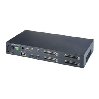
IES-1248-51/51A/53 User’s Guide H A P T E R Front Panel Connections The following table briefly describes the ports on the front panel. Then, the rest of this chapter explains how to make connections to the IES-1248’s front panel. 3.1 Front Panel The following figure shows the front panel of the IES-1248. -
Page 54: Leds
IES-1248-51/51A/53 User’s Guide Table 1 IES-1248 Front Panel Ports (continued) CONNECTOR DESCRIPTION ALARM This DB9 connector has alarm input pins and alarm output pins. Connect the alarm input pins to alarm output terminals on other pieces of equipment. Connect the alarm output pins to an alarm input terminal on another piece of equipment. -
Page 55: 1000/100M Auto-Sensing Ethernet
IES-1248-51/51A/53 User’s Guide 3.2 1000/100M Auto-Sensing Ethernet The IES-1248 has two 1000/100Mbps auto-sensing Ethernet ports. There are two factors related to Ethernet: speed and duplex mode. In 1000/100Mbps Fast Ethernet, the speed can be 100Mbps or 1000Mbps and the duplex mode can be half duplex or full duplex. The auto- negotiation capability makes one Ethernet port able to negotiate with a peer automatically to obtain the connection speed and duplex mode that both ends support. -
Page 56: Transceiver Installation
IES-1248-51/51A/53 User’s Guide Figure 9 SFP Mini GBIC Slot • Type: SFP connection interface • Connection speed: 1 Gigabit per second (Gbps) 3.3.1 Transceiver Installation Use the following steps to install a mini GBIC transceiver (SFP module) in the SFP slot. Note: The SFP slot is at an angle. -
Page 57: Transceiver Removal
IES-1248-51/51A/53 User’s Guide Figure 11 Installed Transceivers 3.3.2 Transceiver Removal Use the following steps to remove a mini GBIC transceiver (SFP module) from the IES-1248. 1 Remove the fiber-optic cables from the transceiver. 2 Unlock the transceiver’s latch (latch styles vary). 3 Pull the transceiver out of the slot. -
Page 58: Console Port Connection
IES-1248-51/51A/53 User’s Guide Figure 13 Removing the Transceiver 3.4 Console Port Connection For local management, you can use a computer with terminal emulation software configured to the following parameters: • VT100 terminal emulation • 9600 bps • No parity, 8 data bits, 1 stop bit •... -
Page 59: Adsl Connections
IES-1248-51/51A/53 User’s Guide Figure 14 ALARM Pins Layout Pin 5 Pin 1 Pin 9 Pin 6 3.6 ADSL Connections USER Connect the lines from the user equipment (ADSL modems) to the Telco-50 connector and the lines from the central office switch or PBX (Private Branch Exchange) to the USER Telco-50 connector. - Page 60 IES-1248-51/51A/53 User’s Guide Chapter 3 Front Panel Connections...
-
Page 61: Chapter 4 Mdf Connections
IES-1248-51/51A/53 User’s Guide H A P T E R MDF Connections This chapter shows you how to connect the Telco-50 connectors to an MDF. 4.1 MDF Connections Overview Observe the following before you start: • See Appendix B on page 445 for the gauge of telephone wire to use. -
Page 62: Telco-50 Cables
IES-1248-51/51A/53 User’s Guide • Use a punch-down tool to seat telephone lines into MDF blocks. • Multiple upper and lower MDF port connections are shown as one line in the following figures. 4.3 Telco-50 Cables Telco-50 cables are used for data and voice applications with MDFs (Main Distribution Frame), patch panels and distribution boxes. -
Page 63: Mdf Scenarios
IES-1248-51/51A/53 User’s Guide See the pin assignments in Appendix C on page 449 Section 4.5 on page 63 for details on Telco-50 connections. 4.5 MDF Scenarios The following figure gives an overview on a possible installation scenario for the IES-1248. Data and voice signals can coexist on the same telephone wiring. -
Page 64: Procedure To Connect To An Mdf
IES-1248-51/51A/53 User’s Guide Figure 18 Installation Scenario A 4.6.1.1 Procedure to Connect to an MDF 1 Connect the Telco-50 connector end of the cable to the Telco-50 connector labeled USER. 2 Connect the wiring on the other end of the Telco-50 cable to the upper ports of the MDF using a punch-down tool. -
Page 65: Procedure To Connect To Mdfs
IES-1248-51/51A/53 User’s Guide • MDF 1 is the original MDF used for telephone connections only. • MDF 2 is used for telephone connections only. • MDF 3 is for DSL service connections. Note: Change the wiring from MDF 1 to MDF 3 for telephone subscribers who want DSL service. -
Page 66: Installation Scenario C
IES-1248-51/51A/53 User’s Guide 9 Change the wiring from MDF 1 to MDF 3 for telephone subscribers who want DSL service. 4.6.3 Installation Scenario C Phone service is also available but there are two MDFs; one for end-user telephone line connections and the other one for CO telephone wiring connections (see the following figure). Note: Users A and B have telephone (only) service. -
Page 67: Procedure To Connect To Mdfs
IES-1248-51/51A/53 User’s Guide Figure 22 Installation Scenario C 4.6.3.1 Procedure to Connect to MDFs 1 Connect the Telco-50 connector end of the cable you want for DSL service to the Telco- 50 connector labeled USER. 2 Connect the wiring on the other side of the Telco-50 cable to the upper ports of MDF 3 using a punch-down tool. - Page 68 IES-1248-51/51A/53 User’s Guide Chapter 4 MDF Connections...
-
Page 69: Chapter 5 Power Connections
IES-1248-51/51A/53 User’s Guide H A P T E R Power Connections This chapter shows you how to connect the IES-1248 to a power source. 5.1 Power Connections Overview Use the following procedures to connect the IES-1248 to a power source after you have installed it in a rack. -
Page 70: Dc Power Connections (Ies-1248-51, Ies-1248-53)
IES-1248-51/51A/53 User’s Guide 5.2.2 DC Power Connections (IES-1248-51, IES-1248-53) Note: When installing the IES-1248 power wire, push the wire firmly into the terminal as deep as possible and make sure that no exposed (bare) wire can be seen or touched. 1 Connect one end of a power wire to the –... -
Page 71: Chapter 6 Fan Maintenance
IES-1248-51/51A/53 User’s Guide H A P T E R Fan Maintenance This chapter describes how to change a fan module. 6.1 Fan Maintenance Introduction The IES-1248 has a hot-swappable fan module. Use the following procedures to remove the fan module. Replace the entire fan module. Return any malfunctioning fan modules to the manufacturer. -
Page 72: Figure 24 Removing The Fan Module
IES-1248-51/51A/53 User’s Guide Figure 24 Removing the Fan Module Figure 25 Fan Module Removed Chapter 6 Fan Maintenance... -
Page 73: Introducing The Web Configurator
IES-1248-51/51A/53 User’s Guide H A P T E R Introducing the Web Configurator This chapter tells how to access and navigate the web configurator. 7.1 Web Configurator Overview The web configurator allows you to use a web browser to manage the IES-1248. 7.2 Screen Privilege Levels There is a high or low privilege level for each screen. -
Page 74: Figure 26 Login
IES-1248-51/51A/53 User’s Guide Figure 26 Login 2 Type admin in the User Name field and your password (default: 1234) in the Password field. Click OK. The main screen appears. This is the web configurator’s main screen. Figure 27 Home A - Click the menu items to open submenu links, and then click on a submenu link to open the screen in the main window. -
Page 75: Navigation Panel
IES-1248-51/51A/53 User’s Guide 7.4 Navigation Panel In the navigation panel, click a menu item to reveal a list of submenu links. Click a submenu link to go to the corresponding screen. Table 3 Navigation Panel Submenu Links BASIC SETTING ADVANCED APPLICATION ROUTING PROTOCOL ALARM MANAGEMENT... - Page 76 IES-1248-51/51A/53 User’s Guide Table 4 Web Configurator Screens (continued) LABEL DESCRIPTION User Account Use this screen to configure system administrator accounts. Switch Setup Use this screen to set up system-wide parameters such as MAC address learning and priority queues. IP Setup Use this screen to configure the system and management IP addresses and subnet masks.
-
Page 77: Changing Your Password
IES-1248-51/51A/53 User’s Guide Table 4 Web Configurator Screens (continued) LABEL DESCRIPTION Static Routing Use this screen to configure static routes. A static route defines how the IES- 1248 should forward traffic by configuring the TCP/IP parameters manually. Alarm Alarm Status Use these screens to view the alarms that are currently in the system. -
Page 78: Saving Your Configuration
IES-1248-51/51A/53 User’s Guide Figure 29 User Account Enter the new password in the Password and Retype Password to confirm fields, and click Modify. Do not forget to click Config Save before you exit the web configurator. See Section 7.6 on page 7.6 Saving Your Configuration Click Apply in a configuration screen when you are done modifying the settings in that screen to save your changes back to the run-time memory. -
Page 79: Figure 30 Logout
IES-1248-51/51A/53 User’s Guide Figure 30 Logout Chapter 7 Introducing the Web Configurator... - Page 80 IES-1248-51/51A/53 User’s Guide Chapter 7 Introducing the Web Configurator...
-
Page 81: Initial Configuration
IES-1248-51/51A/53 User’s Guide H A P T E R Initial Configuration This chapter describes initial configuration for the IES-1248. See Appendix A on page 443 various default settings of the IES-1248. 8.1 Initial Configuration Overview This chapter shows what you first need to do to provide service to ADSL subscribers. 8.2 Initial Configuration This chapter uses the web configurator for initial configuration. -
Page 82: Figure 32 Xdsl Port Setup
IES-1248-51/51A/53 User’s Guide First, you will delete the default virtual channel from all of the ADSL ports. (You cannot edit it). Then, you will configure a new virtual channel for a port and copy it to the other ADSL ports. Adding another virtual channel without deleting the default virtual channel is not recommended since you cannot set the new channel to be the port’s super channel. -
Page 83: Figure 33 Vc Setup
IES-1248-51/51A/53 User’s Guide Figure 33 VC Setup 7 Select any virtual channel’s Select radio button, and click Delete. The following screen appears. Figure 34 VC Setup, Delete 8 Click OK. The following screen appears. Chapter 8 Initial Configuration... -
Page 84: Figure 35 Select Ports
IES-1248-51/51A/53 User’s Guide Figure 35 Select Ports 9 Click All, and then click Apply. The VC Setup screen is updated. Figure 36 VC Setup 10Select Super Channel to allow the channel to forward frames belonging to multiple VLAN groups (that are not assigned to other channels). Then, enter the VPI and VCI that you use. -
Page 85: Figure 37 Vc Setup
IES-1248-51/51A/53 User’s Guide Figure 37 VC Setup 11Select the new channel’s Select radio button. Click Copy, and then click Paste. The following screen appears. The following screen appears. Figure 38 Select Ports 12Click All, and then click Apply. The VC Setup screen is updated. Chapter 8 Initial Configuration... -
Page 86: Figure 39 Vc Setup
IES-1248-51/51A/53 User’s Guide Figure 39 VC Setup 13Click Config Save, Config Save. The Config Save screen appears. Figure 40 Config Save 14Click Save. The following screen should appear. Figure 41 Config Save, Save Successful You can now use the device (with the other settings set to the defaults) to provide service to ADSL subscribers. -
Page 87: Home And Port Statistics Screens
IES-1248-51/51A/53 User’s Guide H A P T E R Home and Port Statistics Screens This chapter describes the Home (status), Port Statistics, and RMON screens. 9.1 Home Screen The Home screen of the web configurator displays a port statistical summary with links to each port showing statistical details. -
Page 88: Ethernet Port Statistics Screen
IES-1248-51/51A/53 User’s Guide Table 5 Home (continued) LABEL DESCRIPTION Status This field displays whether the Ethernet port is connected (Up) or not (Down). Port Name This field displays the name of the Ethernet port. Media This field displays the type of media that this Ethernet port is using for a connection (Copper or Fiber). -
Page 89: Figure 43 Port Statistics (Ethernet)
IES-1248-51/51A/53 User’s Guide Figure 43 Port Statistics (Ethernet) The following table describes the labels in this screen. Table 6 Port Statistics (Ethernet) LABEL DESCRIPTION RMON Click this to open the RMON Statistics screen. Return Click this to go back to the Home screen. Port Use this drop-down list box to select a port for which you wish to view statistics. - Page 90 IES-1248-51/51A/53 User’s Guide Table 6 Port Statistics (Ethernet) (continued) LABEL DESCRIPTION Rx broadcast This field shows the number of good broadcast frames received of 64 to 1518 octets in length (for non VLAN) or 1522 octets (for VLAN), not including multicast frames.
-
Page 91: Adsl Port Statistics Screen
IES-1248-51/51A/53 User’s Guide Table 6 Port Statistics (Ethernet) (continued) LABEL DESCRIPTION packet(65-127) This field shows the number of frames received and transmitted (including bad frames) that were 65 to 127 octets in length (this includes FCS octets but excludes framing bits). packet(128-255) This field shows the number of frames received and transmitted (including bad frames) that were 128 to 255 octets in length (this includes FCS octets but... -
Page 92: Figure 44 Port Statistics (Adsl)
IES-1248-51/51A/53 User’s Guide Figure 44 Port Statistics (ADSL) The following table describes the labels in this screen. Table 7 Port Statistics (ADSL) LABEL DESCRIPTION RMON Click this to open the RMON Statistics screen. Return Click this to go back to the Home screen. xDSL Port Use this drop-down list box to select a port for which you wish to view statistics. -
Page 93: Rmon Statistics Screen
IES-1248-51/51A/53 User’s Guide Table 7 Port Statistics (ADSL) (continued) LABEL DESCRIPTION Rx discard packets This field shows the number of received packets that were dropped on this port. Some of the possible reasons for the discarding of received (rx) packets are: •... -
Page 94: Figure 45 Port Statistics (Rmon)
IES-1248-51/51A/53 User’s Guide Figure 45 Port Statistics (RMON) The following table describes the labels in this screen. Table 8 Port Statistics (RMON) LABEL DESCRIPTION Port Statistics Click this to go back to the previous screen. Enet1 Click this to look at the RMON history for this port. Enet2 Click this to look at the RMON history for this port. -
Page 95: Rmon History Screen
IES-1248-51/51A/53 User’s Guide Table 8 Port Statistics (RMON) (continued) LABEL DESCRIPTION EtherStatsUndersizePkts This field displays the total number of packets that were too small received/transmitted on this port. EtherStatsOversizePkts This field displays the total number of packets that were too big received/transmitted on this port. -
Page 96: Rmon History Detail Screen
IES-1248-51/51A/53 User’s Guide Figure 46 Port Statistics (RMON History)) The following table describes the labels in this screen. Table 9 Port Statistics (RMON History) LABEL DESCRIPTION Index:Interval Select the index of the sample interval and the desired data sampling time (in seconds). -
Page 97: Figure 47 Port Statistics (Rmon History Detail))
IES-1248-51/51A/53 User’s Guide Figure 47 Port Statistics (RMON History Detail)) The following table describes the labels in this screen. Table 10 Port Statistics (RMON History Detail) LABEL DESCRIPTION Click this to return to the previous screen. Refresh Click this to update this screen. Index This field displays the index of the sample interval. - Page 98 IES-1248-51/51A/53 User’s Guide Table 10 Port Statistics (RMON History Detail) (continued) LABEL DESCRIPTION Fragments This is the number of frames received/transmitted that were less than 64 octets long, and contained an invalid FCS, including non-integral and integral lengths. Jabbers This is the number of frames received/transmitted that were longer than 1518 octets (non VLAN) or 1522 octets (VLAN) and contained an invalid FCS, including alignment errors.
-
Page 99: Chapter 10 System Information
IES-1248-51/51A/53 User’s Guide H A P T E R System Information The System Information screen displays general device information (such as firmware version number) and hardware polling information (such as fan status). You can check the firmware version number and monitor the hardware status in this screen. To open this screen, click Basic Setting, System Information. -
Page 100: Figure 48 System Info
IES-1248-51/51A/53 User’s Guide Figure 48 System Info The following table describes the labels in this screen. Table 11 System Info LABEL DESCRIPTION System Name This field displays the device 's model name. ZyNOS F/W Version This field displays the version number of the device’s current firmware including the date created. - Page 101 IES-1248-51/51A/53 User’s Guide Table 11 System Info (continued) LABEL DESCRIPTION DSP Code Version This field displays the Digital Signal Processor firmware version number. This is the modem code firmware. Hardware Version This is the version of the physical device hardware. This field may be blank. Serial Number This is the individual identification number assigned to the device at the factory.
- Page 102 IES-1248-51/51A/53 User’s Guide Table 11 System Info (continued) LABEL DESCRIPTION Status Normal indicates that the RPM is within an acceptable operating range at this point; otherwise Abnormal is displayed. External Alarm The IES-1248 is able to detect alarm input from other equipment connected to the ALARM connector.
-
Page 103: Chapter 11 General Setup
IES-1248-51/51A/53 User’s Guide H A P T E R General Setup The General Setup screen allows you to configure general device identification information. It also allows you to set the system time manually or get the current time and date from an external server when you turn on your device. - Page 104 IES-1248-51/51A/53 User’s Guide Table 12 General Setup (continued) LABEL DESCRIPTION Model This field displays your device type. Use Time Server Select the time service protocol that the timeserver uses. Not all time servers When Bootup support all protocols, so you may have to use trial and error to find a protocol that works.
-
Page 105: Chapter 12 User Account
IES-1248-51/51A/53 User’s Guide H A P T E R User Account The User Account screens allows you to set up and configure system administrator accounts for the IES-1248. You can also configure the authentication policy for IES-1248 administrators. This is different than port authentication in Chapter 26 on page 193. -
Page 106: Authentication Screen
IES-1248-51/51A/53 User’s Guide Table 13 User Account (continued) LABEL DESCRIPTION Privilege Select a privilege level to determine which screens the administrator can use. There is a high, medium or low privilege level for each command. Select high to allow the administrator to use all commands including the lower privilege commands. -
Page 107: Table 14 User Account
IES-1248-51/51A/53 User’s Guide The following table describes the labels in this screen. Table 14 User Account LABEL DESCRIPTION User account Click this to open the User Account screen. See Section 12.1 on page 105. Authentication Mode Select the process by which the IES-1248 authenticates administrators. local - Search the local database. - Page 108 IES-1248-51/51A/53 User’s Guide Chapter 12 User Account...
-
Page 109: Chapter 13 Switch Setup
IES-1248-51/51A/53 User’s Guide H A P T E R Switch Setup The Switch Setup screen allows you to set up and configure global device features. 13.1 GARP Timer Setup GARP (Generic Attribute Registration Protocol) allows network devices to register and de- register attribute values with other GARP participants within a bridged LAN. -
Page 110: Port Isolation With Standalone Switch Mode Example
IES-1248-51/51A/53 User’s Guide 13.2.2 Port Isolation with Standalone Switch Mode Example The following graphic shows IES-1248 1 and 2 connected to each other and the Ethernet backbone switch (3) in a network topology that creates a loop. The IES-1248 are using the standalone switch mode and have RSTP enabled. -
Page 111: Port Isolation With Daisychain Switch Mode Example
IES-1248-51/51A/53 User’s Guide 13.2.4 Port Isolation with Daisychain Switch Mode Example In the example below, the IES-1248 1 has its Ethernet port one (ENET 1) connected to the Ethernet backbone switch (3) and it’s Ethernet port two (ENET2) connected to Ethernet port one (ENET 1) of the daisychained IES-1248 (2). -
Page 112: Figure 54 Switch Setup
IES-1248-51/51A/53 User’s Guide Figure 54 Switch Setup The following table describes the labels in this screen. Table 15 Switch Setup LABEL DESCRIPTION MAC Address Enter a time from 10 to 10,000 seconds. This is how long all dynamically learned Learning MAC addresses remain in the MAC address table before they age out (and must be relearned). - Page 113 IES-1248-51/51A/53 User’s Guide Table 15 Switch Setup (continued) LABEL DESCRIPTION Leave Timer Leave Timer sets the duration of the Leave Period timer for GVRP in milliseconds. Each port has a single Leave Period timer. Leave Time must be two times larger than Join Timer; the default is 600 milliseconds. Leave All Timer Leave All Timer sets the duration of the Leave All Period timer for GVRP in milliseconds.
- Page 114 IES-1248-51/51A/53 User’s Guide Table 15 Switch Setup (continued) LABEL DESCRIPTION Apply Click Apply to save your changes to the IES-1248’s volatile memory. The IES- 1248 loses these changes if it is turned off or loses power, so use the Config Save link on the navigation panel to save your changes to the non-volatile memory when you are done configuring.
-
Page 115: Chapter 14 Ip Setup
IES-1248-51/51A/53 User’s Guide H A P T E R IP Setup The IP Setup screen allows you to configure a device IP address, subnet mask and DNS (domain name server) for management purposes. To open this screen, click Basic Setting, IP Setup. Figure 55 IP Setup The following table describes the labels in this screen. - Page 116 IES-1248-51/51A/53 User’s Guide Chapter 14 IP Setup...
-
Page 117: Chapter 15 Enet Port Setup
IES-1248-51/51A/53 User’s Guide H A P T E R ENET Port Setup The ENET Port Setup screen allows you to configure settings for the Ethernet ports. To open this screen, click Basic Setting, ENET Port Setup. Figure 56 ENET Port Setup The following table describes the labels in this screen. - Page 118 IES-1248-51/51A/53 User’s Guide Table 17 ENET Port Setup (continued) LABEL DESCRIPTION Apply Click Apply to save your changes to the IES-1248’s volatile memory. The IES- 1248 loses these changes if it is turned off or loses power, so use the Config Save link on the navigation panel to save your changes to the non-volatile memory when you are done configuring.
-
Page 119: Chapter 16 Xdsl Port Setup
IES-1248-51/51A/53 User’s Guide H A P T E R xDSL Port Setup This chapter explains how to configure settings for profiles and individual ADSL ports. It also covers how to configure virtual channels and virtual channel profiles. 16.1 ADSL Standards Overview These are the ADSL standards and rates that the IES-1248 supports at the time of writing. -
Page 120: Profiles
IES-1248-51/51A/53 User’s Guide 16.3 Profiles A profile is a table that contains a list of pre-configured ADSL settings. Each ADSL port has one (and only one) profile assigned to it at any given time. You can configure multiple profiles, including profiles for troubleshooting. Profiles allow you to configure ADSL ports efficiently. -
Page 121: Default Settings
IES-1248-51/51A/53 User’s Guide Regardless of a profile’s configured upstream and downstream rates, the IES-1248 automatically limits the actual rates for each individual port to the maximum speeds supported by the port’s ADSL operational mode. For example, if you configure a profile with a maximum downstream rate of 25000 Kbps, and apply it to a port set to use G.dmt, the IES- 1248 automatically uses a maximum downstream rate of 8160 Kbps. -
Page 122: Figure 58 Select Ports
IES-1248-51/51A/53 User’s Guide Table 19 xDSL Port Setup (continued) LABEL DESCRIPTION Copy Port Do the following to copy settings from one DSL port to another DSL port or ports. Paste 1 Select the number of the DSL port from which you want to copy settings. -
Page 123: Xdsl Port Setting Screen
IES-1248-51/51A/53 User’s Guide Table 19 xDSL Port Setup (continued) LABEL DESCRIPTION PVID & Priority Select this check box to copy this port’s PVID and priority settings. These are configured in the VLAN Port Setting screen (see Chapter 19 on page 157). -
Page 124: Figure 59 Xdsl Port Setting
IES-1248-51/51A/53 User’s Guide Figure 59 xDSL Port Setting The following table describes the labels in this screen. Table 20 xDSL Port Setting LABEL DESCRIPTION Last Page Click this to return to the previous screen. General Setup Active Select this check box to turn on this ADSL port. Customer Info Enter information to identify the subscriber connected to this ADSL port. - Page 125 IES-1248-51/51A/53 User’s Guide Table 20 xDSL Port Setting (continued) LABEL DESCRIPTION Alarm Profile Select the port’s alarm profile. The alarm profile defines alarm thresholds for the ADSL port. The IES-1248 sends an alarm trap and generates a syslog entry when the thresholds of the alarm profile are exceeded (see Section 17.6 on page 145).
- Page 126 IES-1248-51/51A/53 User’s Guide Table 20 xDSL Port Setting (continued) LABEL DESCRIPTION L2 Time Set minimum time (in seconds) that the ADSL line must stay in the L2 power mode before reducing the power again in the L2 power mode. L2 ATPR Set the maximum Aggregate Transmit Power Reduction (ATPR) in decibels (dB) that is permitted in a L2 power reduction.
-
Page 127: Virtual Channels
IES-1248-51/51A/53 User’s Guide Table 20 xDSL Port Setting (continued) LABEL DESCRIPTION DS Carrier(256~511) Mask0 represents tones 256~287 Mask1 represents tones 288~319 Mask2 represents tones 320~351 Mask3 represents tones 352~383 Mask4 represents tones 384~415 Mask5 represents tones 416~447 Mask6 represents tones 448~479 Mask7 represents tones 480~511 For example, use 0x00001000 in Mask1 to disable downstream carrier tone 307. -
Page 128: Llc
IES-1248-51/51A/53 User’s Guide 16.8.2 LLC LLC is a type of encapsulation where one VC (Virtual Circuit) carries multiple protocols with each packet header containing protocol identifying information. Despite the extra bandwidth and processing overhead, this method may be advantageous if it is not practical to have a separate VC for each carried protocol, for example, if charging heavily depends on the number of simultaneous VCs. -
Page 129: Figure 60 Vc Setup
IES-1248-51/51A/53 User’s Guide Figure 60 VC Setup The following table describes the labels in this screen. Table 21 VC Setup LABEL DESCRIPTION xDSL Port Setup Click xDSL Port Setup to go to the screen where you can configure DSL port settings (see Section 16.7 on page 121). - Page 130 IES-1248-51/51A/53 User’s Guide Table 21 VC Setup (continued) LABEL DESCRIPTION US VC Profile Use the drop-down list box to select a VC profile to use for this channel’s upstream traffic. The IES-1248 does not perform upstream traffic policing if you do not specify an upstream VC profile.
-
Page 131: Figure 61 Basic Setting, Xdsl Port Setup, Vc Setup, Delete
IES-1248-51/51A/53 User’s Guide Table 21 VC Setup (continued) LABEL DESCRIPTION Select Do the following to remove one or more PVCs. Delete 1 Select a PVC’s Select radio button. 2 Click Delete. 3 Click OK if you want to remove the PVC from other ports. Click Cancel to only remove the one you selected. -
Page 132: Priority-Based Pvcs
IES-1248-51/51A/53 User’s Guide Table 21 VC Setup (continued) LABEL DESCRIPTION Select Do the following to copy settings from one PVC to another port or ports. Copy 1 Click the Select radio button of the PVC from which you want to Paste copy settings. -
Page 133: Ppvc Setup Screen
IES-1248-51/51A/53 User’s Guide Table 22 IEEE 802.1p Priority to PPVC Mapping (continued) IEEE 802.1 PRIORITY MAPS TO: PPVC 0/33, PRIORITY QUEUE -> level 1 > level 0 16.11 PPVC Setup Screen Use this screen to view and configure PPVCs. To open this screen, click Basic Setting, xDSL Port Setup, PPVC Setup. Figure 64 PPVC Setup The following table describes the labels in this screen. -
Page 134: Ppvc Setup Members Screen
IES-1248-51/51A/53 User’s Guide Table 23 PPVC Setup (continued) LABEL DESCRIPTION Priority Use the drop-down list box to select the priority value (0 to 7) to add to incoming frames without a (IEEE 802.1p) priority tag. Add / Modify Click Add / Modify to save PPVC settings for a port. In order to change a port’s PPVC settings, just select the port from the Port drop-down list box and then configure the settings you want. -
Page 135: Figure 65 Ppvc Setup, Edit
IES-1248-51/51A/53 User’s Guide Figure 65 PPVC Setup, Edit The following table describes the labels in this screen. Table 24 PPVC Setup, Edit LABEL DESCRIPTION Port This is the port for which you are viewing or configuring settings. Index This field displays the number of the member PVC. VPI/VCI This field displays the Virtual Path Identifier (VPI) and Virtual Circuit Identifier (VCI). - Page 136 IES-1248-51/51A/53 User’s Guide Table 24 PPVC Setup, Edit (continued) LABEL DESCRIPTION Add / Modify Click Add / Modify to save member PVC settings for a PPVC. In order to change a member PVC ‘s settings, just enter the PVC’s VPI and VCI, and configure the settings you want.
-
Page 137: Chapter 17 Xdsl Profiles Setup
IES-1248-51/51A/53 User’s Guide H A P T E R xDSL Profiles Setup A profile is a list of settings that you define. Then you can assign them to one or more individual ports. For background information about many of these settings, see Chapter 16 on page 119. -
Page 138: Table 25 Port Profile
IES-1248-51/51A/53 User’s Guide The following table describes the labels in this screen. Table 25 Port Profile LABEL DESCRIPTION VC Profile Click VC Profile to open the VC Profile screen where you can configure virtual channel profiles (see Section 17.5 on page 143). - Page 139 IES-1248-51/51A/53 User’s Guide Table 25 Port Profile (continued) LABEL DESCRIPTION Target SNR Type the target upstream signal to noise margin (0-31 dB). Configure the target upstream signal to noise margin to be greater than or equal to the minimum upstream signal to noise margin and less than or equal to the maximum upstream signal to noise margin.
-
Page 140: Atm Qos
IES-1248-51/51A/53 User’s Guide 17.2 ATM QoS ATM Quality of Service (QoS) mechanisms provide the best service on a per-flow guarantee. ATM network infrastructure was designed to provide QoS. It uses fixed cell sizes and built-in traffic management (see Section 17.3 on page 140). -
Page 141: Unspecified Bit Rate (Ubr)
IES-1248-51/51A/53 User’s Guide 17.3.1.3 Unspecified Bit Rate (UBR) The Unspecified Bit Rate (UBR) ATM traffic class is similar to the ABR traffic class for bursty data transfers. However, while ABR gives subscribers a set amount of bandwidth, UBR doesn’t guarantee any bandwidth and only delivers traffic when the network has spare bandwidth. -
Page 142: Cell Delay Variation Tolerance (Cdvt)
IES-1248-51/51A/53 User’s Guide Figure 67 PCR, SCR and MBS in Traffic Shaping 17.3.2.4 Cell Delay Variation Tolerance (CDVT) Cell Delay Variation Tolerance (CDVT) is the accepted tolerance of the difference between a cell’s transfer delay and the expected transfer delay. CDVT controls the time scale over which the PCR is enforced. -
Page 143: Upstream Policing
IES-1248-51/51A/53 User’s Guide 17.4 Upstream Policing Upstream policing is an agreement between the carrier and the subscriber to regulate the average rate and fluctuations of data transmission coming from the subscriber's device to the IES-1248. Note: Upstream policing controls incoming (upstream) traffic, not outgoing (downstream). -
Page 144: Figure 69 Vc Profile
IES-1248-51/51A/53 User’s Guide Figure 69 VC Profile The following table describes the labels in this screen. Table 26 VC Profile LABEL DESCRIPTION Port Profile Click Port Profile to configure port profiles and assign them to individual ports (see Section 17.1 on page 137). -
Page 145: Alarm Profile Screen
IES-1248-51/51A/53 User’s Guide Table 26 VC Profile (continued) LABEL DESCRIPTION Name When editing a profile, this is the name of this profile. When adding a profile, type a name for the profile. You can use up to 31 ASCII characters; spaces are not allowed. -
Page 146: Figure 70 Alarm Profile
IES-1248-51/51A/53 User’s Guide Figure 70 Alarm Profile The following table describes the labels in this screen. Table 27 Alarm Profile LABEL DESCRIPTION Port Profile Click Port Profile to open the Port Profile screen (see Section 17.1 on page 137). Use the Port Profile screen to configure profiles of ADSL port settings (such as the transfer rate, interleave delay and signal to noise ratio settings). -
Page 147: Igmp Filtering
IES-1248-51/51A/53 User’s Guide Table 27 Alarm Profile (continued) LABEL DESCRIPTION Threshold Specify limits for the individual performance counters. The IES-1248 sends an alarm trap and generates a syslog entry when one of these thresholds is exceeded. A value of 0 disables the alarm threshold. ATU-C These fields are for traffic coming from the subscriber’s device to the IES-1248. -
Page 148: Igmp Filter Profile Screen
IES-1248-51/51A/53 User’s Guide You can set the device to filter the multicast group join reports on a per-port basis by configuring an IGMP filtering profile and associating the profile to a port. 17.8 IGMP Filter Profile Screen You can use the IGMP filter profiles to control access to a service that uses a specific multicast group (like a SIP server for example). -
Page 149: Figure 71 Igmp Filter Profile
IES-1248-51/51A/53 User’s Guide Figure 71 IGMP Filter Profile The following table describes the labels in this screen. Table 28 IGMP Filter Profile LABEL DESCRIPTION Port Profile Click Port Profile to configure port profiles and assign them to individual ports (see Section 17.1 on page 137). - Page 150 IES-1248-51/51A/53 User’s Guide Table 28 IGMP Filter Profile (continued) LABEL DESCRIPTION End IP Enter the ending multicast IP address for a range of IP addresses to which you want this IGMP filter profile to allow access. If you want to add a single multicast IP address, enter it in both the Start IP and End IP fields.
-
Page 151: Chapter 18 Xdsl Line Data
IES-1248-51/51A/53 User’s Guide H A P T E R xDSL Line Data 18.1 xDSL Line Rate Info Screen This screen displays an ADSL port’s line operating values. Information obtained prior to training to steady state transition will not be valid or will be old information. To open this screen, click Basic Setting, xDSL Line Data. - Page 152 IES-1248-51/51A/53 User’s Guide Table 29 xDSL Line Rate Info (continued) LABEL DESCRIPTION Port Name This section displays the name of the port. Rate The rate fields display the transmission rates. “Line Down” indicates that the ADSL port is not connected to a subscriber. Down/up Stream These are the rates (in Kbps) at which the port has been sending and receiving Rate...
-
Page 153: Xdsl Performance Screen
IES-1248-51/51A/53 User’s Guide 18.2 xDSL Performance Screen These counters display line performance data that has been accumulated since the system started. The definitions of near end/far end are always relative to the ATU-C (ADSL Termination Unit-Central Office). ATU-C refers to downstream traffic from the IES-1248. ATU-R (ADSL Termination Unit-Remote) refers to upstream traffic from the subscriber. -
Page 154: Table 30 Xdsl Performance
IES-1248-51/51A/53 User’s Guide The following table describes the labels in this screen. Table 30 xDSL Performance LABEL DESCRIPTION Line Rate Click Line Rate to display an ADSL port’s line operating values (see Section 18.1 on page 151). Line Data Click Line Data to display an ADSL port’s line bit allocation (see Section 18.3 on page 155). -
Page 155: Xdsl Line Data Screen
IES-1248-51/51A/53 User’s Guide Table 30 xDSL Performance (continued) LABEL DESCRIPTION lprs The number of Loss of Power Seconds that have occurred within the period. The number of Errored Seconds that have occurred within the period. init The number of successful initializations that have occurred within the period. The number of Severely Errored Seconds that have occurred within the period. -
Page 156: Table 31 Xdsl Line Data
IES-1248-51/51A/53 User’s Guide The following table describes the labels in this screen. Table 31 xDSL Line Data LABEL DESCRIPTION Line Rate Click Line Rate to display an ADSL port’s line operating values (see Section 18.1 on page 151). Line Performance Click Line Performance to display an ADSL port’s line performance counters (see Section 18.2 on page... -
Page 157: Chapter 19 Vlan
IES-1248-51/51A/53 User’s Guide H A P T E R VLAN This chapter shows you how to configure IEEE 802.1Q tagged VLANs. 19.1 Introduction to VLANs A VLAN (Virtual Local Area Network) allows a physical network to be partitioned into multiple logical networks. Devices on a logical network belong to one group. A device can belong to more than one group. -
Page 158: Forwarding Tagged And Untagged Frames
IES-1248-51/51A/53 User’s Guide ID are independent of each other. A frame with VID (VLAN Identifier) of null (0) is called a priority frame, meaning that only the priority level is significant and the default VID of the ingress port is given as the VID of the frame. Of the 4096 possible VIDs, a VID of 0 is used to identify priority frames and value 4095 (FFF) is reserved, so the maximum possible VLAN configurations are 4,094. -
Page 159: Figure 75 Vlan Status
IES-1248-51/51A/53 User’s Guide Figure 75 VLAN Status The following table describes the labels in this screen. Table 32 VLAN Status LABEL DESCRIPTION Static VLAN Setting Click Static VLAN Setting to configure ports to dynamically join a VLAN group or permanently assign ports to a VLAN group or prohibit ports from joining a VLAN group (see Section 19.4 on page 160). -
Page 160: Static Vlan Setting Screen
IES-1248-51/51A/53 User’s Guide Table 32 VLAN Status (continued) LABEL DESCRIPTION Elapsed Time This field shows how long it has been since a normal VLAN was registered or a static VLAN was set up. Status This field shows that this VLAN was added to the IES-1248 statically, that is, added as a permanent entry. -
Page 161: Vlan Port Setting Screen
IES-1248-51/51A/53 User’s Guide The following table describes the labels in this screen. Table 33 Static VLAN Setting LABEL DESCRIPTION VLAN Status Click VLAN Status to see which of the IES-1248’s ports are members of which VLANs (see Section 19.3 on page 158) VLAN Port Setting Click VLAN Port Setting to specify Port VLAN IDs (PVIDs). -
Page 162: Figure 77 Vlan Port Setting
IES-1248-51/51A/53 User’s Guide Figure 77 VLAN Port Setting The following table describes the labels in this screen. Table 34 VLAN Port Setting LABEL DESCRIPTION VLAN Status Click VLAN Status to see which of the IES-1248’s ports are members of which VLANs (see Section 19.3 on page 158). -
Page 163: Figure 78 Select Ports
IES-1248-51/51A/53 User’s Guide Table 34 VLAN Port Setting (continued) LABEL DESCRIPTION Cancel Click Cancel to begin configuring this screen afresh. Copy port Do the following to copy settings from one port to another port or ports. Paste 1 Select the number of the port from which you want to copy settings. 2 Click Paste and the following screen appears. - Page 164 IES-1248-51/51A/53 User’s Guide Chapter 19 VLAN...
-
Page 165: Chapter 20 Igmp
IES-1248-51/51A/53 User’s Guide H A P T E R IGMP This chapter describes the IGMP screens. 20.1 IGMP Traditionally, IP packets are transmitted in one of either two ways - Unicast (1 sender to 1 recipient) or Broadcast (1 sender to everybody on the network). Multicast delivers IP packets to just a group of hosts on the network. -
Page 166: Igmp Status Screen
IES-1248-51/51A/53 User’s Guide In IGMP proxy, an upstream interface is the port that is closer to the source (or the root of the multicast tree) and is able to receive multicast traffic. There should only be one upstream interface (also known as the query port) for one query VLAN on the IES-1248. A downstream interface is a port that connects to a host (such as a computer). -
Page 167: Figure 80 Igmp (Status)
IES-1248-51/51A/53 User’s Guide Figure 80 IGMP (Status) The following table describes the labels in this screen. Table 35 IGMP (Status) LABEL DESCRIPTION Bandwidth Setup Click Bandwidth Setup to open the IGMP Bandwidth screen where you can set up bandwidth requirements for multicast channels (see Section 20.4 on page 168). -
Page 168: Igmp Bandwidth Screen
IES-1248-51/51A/53 User’s Guide Table 35 IGMP (Status) (continued) LABEL DESCRIPTION Page X of X This identifies which page of information is displayed and the total number of pages of information. The first table displays the names of the fields. The subsequent tables show the settings of the IGMP groups. -
Page 169: Bandwidth Port Setup Screen
IES-1248-51/51A/53 User’s Guide The following table describes the labels in this screen. Table 36 IGMP Bandwidth LABEL DESCRIPTION Port Setup Click Port Setup to open the Bandwidth Port Setup screen where you can set up multicast bandwidth requirements on specified ports (see Section 20.4.1 on page 169). -
Page 170: Igmp Setup Screen
IES-1248-51/51A/53 User’s Guide Figure 82 Bandwidth Port Setup The following table describes the labels in this screen. Table 37 Bandwidth Port Setup LABEL DESCRIPTION Bandwidth Setup Click Bandwidth Setup to open the IGMP Bandwidth screen where you can set up bandwidth requirements for multicast channels (see Section 20.4 on page 168). -
Page 171: Igmp Filter Setup Screen
IES-1248-51/51A/53 User’s Guide Figure 83 IGMP Setup The following table describes the labels in this screen. Table 38 IGMP Setup LABEL DESCRIPTION IGMP Status Click IGMP Status to open the IGMP Setup screen where you can view current IGMP information (see Section 20.3 on page 166). -
Page 172: Igmp Port Info Screen
IES-1248-51/51A/53 User’s Guide Figure 84 IGMP Count The following table describes the labels in this screen. Table 39 IGMP Count LABEL DESCRIPTION IGMP Status Click IGMP Status to open the IGMP Setup screen where you can view current IGMP information (see Section 20.3 on page 166). -
Page 173: Igmp Port Group Screen
IES-1248-51/51A/53 User’s Guide Figure 85 IGMP Port Info The following table describes the labels in this screen. Table 40 IGMP Port Info LABEL DESCRIPTION IGMP Status Click IGMP Status to open the IGMP Setup screen where you can view current IGMP information (see Section 20.3 on page 166). -
Page 174: Table 41 Igmp Port Group
IES-1248-51/51A/53 User’s Guide The following table describes the labels in this screen. Table 41 IGMP Port Group LABEL DESCRIPTION IGMP Status Click IGMP Status to open the IGMP Setup screen where you can view current IGMP information (see Section 20.3 on page 166). -
Page 175: Chapter 21 Static Multicast
IES-1248-51/51A/53 User’s Guide H A P T E R Static Multicast This chapter describes the Static Multicast screen. 21.1 Static Multicast Use static multicast to allow incoming frames based on multicast MAC address(es) that you specify. This feature can be used in conjunction with IGMP snooping/proxy to allow multicast MAC address(es) that are not learned by IGMP snooping or IGMP proxy. - Page 176 IES-1248-51/51A/53 User’s Guide Table 42 Static Multicast (continued) LABEL DESCRIPTION Previous Click one of these buttons to show the previous/next screen if all status information cannot be seen in one screen. Next Reload Click this button to refresh the screen. The first table displays the names of the fields.
-
Page 177: Chapter 22 Multicast Vlan
IES-1248-51/51A/53 User’s Guide H A P T E R Multicast VLAN This chapter describes the Multicast VLAN screens. 22.1 Multicast VLAN Overview Multicast VLAN allows one single multicast VLAN to be shared among different subscriber VLANs on the network. This improves bandwidth utilization by reducing multicast traffic in the subscriber VLANs and simplifies multicast group management. -
Page 178: Mvlan Setup Screen
IES-1248-51/51A/53 User’s Guide The following table describes the labels in this screen. Table 43 MVLAN Status LABEL DESCRIPTION MVLAN Setup Click MVLAN Setup to open the MVLAN Setup screen where you can configure basic settings and port members for each multicast VLAN (see Section 22.3 on page 178). -
Page 179: Figure 89 Mvlan Setup
IES-1248-51/51A/53 User’s Guide Figure 89 MVLAN Setup The following table describes the labels in this screen. Table 44 MVLAN Setup LABEL DESCRIPTION MVLAN Status Click MVLAN Status to open the MVLAN Status screen where you can view a summary of all multicast VLAN on the IES-1248 (see Section 22.2 on page 177). -
Page 180: Mvlan Group Screen
IES-1248-51/51A/53 User’s Guide Table 44 MVLAN Setup (continued) LABEL DESCRIPTION Name Enter a descriptive name for the multicast VLAN. The name can be 1-31 printable ASCII characters long. Spaces are not allowed. VLAN ID Enter the VLAN ID of the multicast VLAN; the valid range is between 1 and 4094. -
Page 181: Table 45 Mvlan Group
IES-1248-51/51A/53 User’s Guide The following table describes the labels in this screen. Table 45 MVLAN Group LABEL DESCRIPTION MVLAN Status Click MVLAN Status to open the MVLAN Status screen where you can view a summary of all multicast VLAN on the IES-1248 (see Section 22.2 on page 177). - Page 182 IES-1248-51/51A/53 User’s Guide Chapter 22 Multicast VLAN...
-
Page 183: Chapter 23 Filtering
IES-1248-51/51A/53 User’s Guide H A P T E R Filtering This chapter describes how to configure the Packet Filter screen. 23.1 Packet Filter Screen Use this screen to set which types of packets the IES-1248 accepts on individual ADSL ports. To open this screen, click Advanced Application, Filtering. - Page 184 IES-1248-51/51A/53 User’s Guide Table 46 Packet Filter (continued) LABEL DESCRIPTION PPPoE Pass through Point-to-Point Protocol over Ethernet relies on PPP and Ethernet. It is a specification for connecting the users on an Ethernet to the Internet through a common broadband medium, such as a single DSL line, wireless device or cable modem.
-
Page 185: Chapter 24 Mac Filter
IES-1248-51/51A/53 User’s Guide H A P T E R MAC Filter This chapter introduces the MAC filter. 24.1 MAC Filter Introduction Use the MAC filter to control from which MAC (Media Access Control) addresses frames can (or cannot) come in through a port. 24.2 MAC Filter Screen To open this screen, click Advanced Application, MAC Filter. - Page 186 IES-1248-51/51A/53 User’s Guide Table 47 MAC Filter (continued) LABEL DESCRIPTION Click Add to save your changes to the IES-1248’s volatile memory. The IES- 1248 loses these changes if it is turned off or loses power, so use the Config Save link on the navigation panel to save your changes to the non-volatile memory when you are done configuring.
-
Page 187: Spanning Tree Protocol
IES-1248-51/51A/53 User’s Guide H A P T E R Spanning Tree Protocol This chapter introduces the Spanning Tree Protocol (STP) and Rapid Spanning Tree Protocol (RSTP). 25.1 RSTP and STP RSTP adds rapid reconfiguration capability to STP. The IES-1248 supports RSTP and the earlier STP. -
Page 188: Figure 93 Stp Root Ports And Designated Ports
IES-1248-51/51A/53 User’s Guide After a bridge determines the lowest cost-spanning tree with RSTP, it enables the root port and the ports that are the designated ports for the connected LANs, and disables all other ports that participate in RSTP. Network packets are therefore only forwarded between enabled ports, eliminating any possible network loops. -
Page 189: Spanning Tree Protocol Status Screen
IES-1248-51/51A/53 User’s Guide Table 49 RSTP Port States (continued) RSTP PORT STATE STP PORT STATE DESCRIPTION Discarding Listening In RSTP, BPDUs are discarded. In STP, all BPDUs are received and processed. Learning Learning All BPDUs are received and processed. Information frames are submitted to the learning process but not forwarded. -
Page 190: Table 50 Spanning Tree Protocol Status
IES-1248-51/51A/53 User’s Guide The following table describes the labels in this screen. Table 50 Spanning Tree Protocol Status LABEL DESCRIPTION STP Config Click STP Config to modify the IES-1248’s STP settings (see Section 25.3 on page 191). Spanning Tree This field displays On if STP is activated. Otherwise, it displays Off. Protocol Bridge Status If STP is activated, the following fields appear. -
Page 191: Spanning Tree Protocol Screen
IES-1248-51/51A/53 User’s Guide Table 50 Spanning Tree Protocol Status (continued) LABEL DESCRIPTION Cost to root This is the path cost from the root port on this switch to the root switch. Designated bridge This is the unique identifier for the bridge that has the lowest path cost to reach the root bridge, consisting of bridge priority plus MAC address. - Page 192 IES-1248-51/51A/53 User’s Guide Table 51 Spanning Tree Protocol (continued) LABEL DESCRIPTION Bridge Priority Bridge priority is used in determining the root switch, root port and designated port. The switch with the highest priority (lowest numeric value) becomes the STP root switch. If all switches have the same priority, the switch with the lowest MAC address will then become the root switch.
-
Page 193: Chapter 26 Port Authentication
IES-1248-51/51A/53 User’s Guide H A P T E R Port Authentication This chapter describes the 802.1x authentication method and RADIUS server connection setup. 26.1 Introduction to Authentication IEEE 802.1x is an extended authentication protocol that allows support of RADIUS (Remote Authentication Dial In User Service, RFC 2138, 2139) for centralized user profile management on a network RADIUS server. -
Page 194: Radius Screen
IES-1248-51/51A/53 User’s Guide 26.2 RADIUS Screen To open this screen, click Advanced Application, Port Authentication. Figure 97 RADIUS The following table describes the labels in this screen. Table 52 RADIUS LABEL DESCRIPTION 802.1x Click 802.1x to configure individual port authentication settings (see Section 26.3 on page 195). -
Page 195: Screen
IES-1248-51/51A/53 User’s Guide Table 52 RADIUS (continued) LABEL DESCRIPTION Name Type the user name of the user profile. Password Type a password up to 31 characters long for this user profile. Retype Password to Type the password again to make sure you have entered it properly. confirm Click Add to save your changes to the IES-1248’s volatile memory. -
Page 196: Table 53 802.1X
IES-1248-51/51A/53 User’s Guide The following table describes the labels in this screen. Table 53 802.1x LABEL DESCRIPTION RADIUS/Local Click this link to configure the RADIUS server or local profile settings (see Profile Section 26.2 on page 194). Enable Select this check box to turn on IEEE 802.1x authentication on the switch. Apply Click Apply to save your changes to the IES-1248’s volatile memory. -
Page 197: Chapter 27 Port Security
IES-1248-51/51A/53 User’s Guide H A P T E R Port Security This chapter shows you how to set up port security. 27.1 Port Security Overview Port security allows you to restrict the number of MAC addresses that can be learned on a port. 27.2 Port Security Screen To open this screen, click Advanced Application, Port Security. -
Page 198: Figure 100 Select Ports
IES-1248-51/51A/53 User’s Guide Table 54 Port Security (continued) LABEL DESCRIPTION Apply Click Apply to save your changes to the IES-1248’s volatile memory. The IES- 1248 loses these changes if it is turned off or loses power, so use the Config Save link on the navigation panel to save your changes to the non-volatile memory when you are done configuring. -
Page 199: Chapter 28 Dhcp Relay
IES-1248-51/51A/53 User’s Guide H A P T E R DHCP Relay This chapter shows you how to set up DHCP relays for each VLAN. 28.1 DHCP Relay DHCP (Dynamic Host Configuration Protocol, RFC 2131 and RFC 2132) allows individual clients to obtain TCP/IP configuration at start-up from a DHCP server. You can configure the IES-1248 to relay DHCP requests to one or more DHCP servers and the server’s responses back to the clients. -
Page 200: Dhcp Relay Screen
IES-1248-51/51A/53 User’s Guide The Agent Information field that the IES-1248 adds also contains an “Agent Remote-ID sub- option” of information that you specify. The following figure shows the format of the Agent Remote ID sub-option. The 2 in the first field identifies this as an Agent Remote ID sub-option. -
Page 201: Table 55 Dhcp Relay
IES-1248-51/51A/53 User’s Guide The following table describes the labels in this screen. Table 55 DHCP Relay LABEL DESCRIPTION Enable DHCP Relay: Enable DHCP relay to have the IES-1248 relay DHCP requests to a DHCP server and the server’s responses back to the clients. Relay Mode Specify how the IES-1248 relays DHCP requests. - Page 202 IES-1248-51/51A/53 User’s Guide Table 55 DHCP Relay (continued) LABEL DESCRIPTION Secondary Server IP This field displays the IP address of a second DHCP server to which the switch should relay DHCP requests. This field is 0.0.0.0 if the primary server is the only DHCP relay.
-
Page 203: Chapter 29 Dhcp Snoop
IES-1248-51/51A/53 User’s Guide H A P T E R DHCP Snoop This chapter shows you how to set up DHCP snooping settings on the subscriber ports. 29.1 DHCP Snoop Overview DHCP snooping prevents clients from assigning their own IP addresses. The IES-1248 can store every (ADSL port, MAC address, IP address) tuple offered by the DHCP server. -
Page 204: Dhcp Snoop Status Screen
IES-1248-51/51A/53 User’s Guide Table 56 DHCP Snoop (continued) LABEL DESCRIPTION Active This field displays whether DHCP snooping is active (“V”) or inactive (“-”) on this port. Select Select this, and click Active or Inactive to enable or disable the DHCP snooping on this port. -
Page 205: Dhcp Counter Screen
IES-1248-51/51A/53 User’s Guide Table 57 DHCP Snoop Status (continued) LABEL DESCRIPTION This field displays the MAC address of a client on this port to which the DHCP server assigned an IP address. Flush Click Flush to remove all of the entries from the DHCP snooping table for the selected port(s). - Page 206 IES-1248-51/51A/53 User’s Guide Table 58 DHCP Counter (continued) LABEL DESCRIPTION Overflow The DHCP server can assign up to 32 IP addresses at one time to each port. This field displays the number of requests from DHCP clients above this limit. Clear Click Clear to delete the information the IES-1248 has learned about DHCP packets.
-
Page 207: 2684 Routed Mode
IES-1248-51/51A/53 User’s Guide H A P T E R 2684 Routed Mode This chapter shows you how to set up 2684 routed mode service. 30.1 2684 Routed Mode Use the 2684 (formerly 1483) routed mode to have the IES-1248 add MAC address headers to 2684 routed mode traffic from a PVC that connects to a subscriber device that uses 2684 routed mode. -
Page 208: 2684 Routed Pvc Screen
IES-1248-51/51A/53 User’s Guide Figure 107 2684 Routed Mode Example Note the following. • The CPE device’s WAN IP (192.168.10.200 in this example) must be in the same subnet as the gateway’s IP address (192.168.10.102 in this example). • The IES-1248's management IP address can be any IP address, it doesn't have any relationship to the WAN IP address or routed gateway IP address. -
Page 209: Figure 108 2684 Routed Pvc
IES-1248-51/51A/53 User’s Guide Figure 108 2684 Routed PVC The following table describes the labels in this screen. Table 59 2684 Routed PVC LABEL DESCRIPTION Routed Domain Click Routed Domain to open this screen where you can configure domains for 2684 routed mode traffic (see Section 30.3 on page 210). -
Page 210: 2684 Routed Domain Screen
IES-1248-51/51A/53 User’s Guide Table 59 2684 Routed PVC (continued) LABEL DESCRIPTION Port This field displays the number of the ADSL port on which the routed PVC is configured. This field displays the Virtual Path Identifier (VPI) The VPI and VCI identify a channel on this port. -
Page 211: Rpvc Arp Proxy Screen
IES-1248-51/51A/53 User’s Guide The following table describes the labels in this screen. Table 60 2684 Routed Domain LABEL DESCRIPTION RPVC ARP Proxy Click RPVC ARP Proxy to go to the screen where you can view the Address Resolution Protocol table of IP addresses of CPE devices using 2684 routed mode and configure how long the device is to store them (see Section 30.4 on page... -
Page 212: 2684 Routed Gateway Screen
IES-1248-51/51A/53 User’s Guide To open this screen, click Advanced Application, 2684 Routed Mode, RPVC ARP Proxy. Figure 110 RPVC Arp Proxy The following table describes the labels in this screen. Table 61 RPVC Arp Proxy LABEL DESCRIPTION Routed Domain Click Routed Domain to open this screen where you can configure domains for 2684 routed mode traffic (see Section 30.3 on page 210). -
Page 213: Figure 111 2684 Routed Gateway
IES-1248-51/51A/53 User’s Guide Figure 111 2684 Routed Gateway The following table describes the labels in this screen. Table 62 2684 Routed Gateway LABEL DESCRIPTION Routed PVC Click Routed PVC to go to the screen where you can configure routed PVC settings (see Section 30.2 on page 208). - Page 214 IES-1248-51/51A/53 User’s Guide Chapter 30 2684 Routed Mode...
-
Page 215: Chapter 31 Pppoa To Pppoe
IES-1248-51/51A/53 User’s Guide H A P T E R PPPoA to PPPoE This chapter shows you how to set up the IES-1248 to convert PPPoA frames to PPPoE traffic and vice versa. 31.1 PPPoA to PPPoE Overview Before migrating to an Ethernet infrastructure, a broadband network might consist of PPPoA connections between the CPE devices and the DSLAM and PPPoE connections from the DSLAM to the Broadband Remote Access Server (BRAS). -
Page 216: Figure 113 Pppoa To Pppoe
IES-1248-51/51A/53 User’s Guide Figure 113 PPPoA to PPPoE The following table describes the labels in this screen. Table 63 PPPoA to PPPoE LABEL DESCRIPTION Port Use this drop-down list box to select a port for which you wish to set up PPPoA to PPPoE conversions. - Page 217 IES-1248-51/51A/53 User’s Guide Table 63 PPPoA to PPPoE (continued) LABEL DESCRIPTION Priority Use the drop-down list box to select the priority value (0 to 7) to add to incoming frames without a (IEEE 802.1p) priority tag. AC Name This field is optional. Specify the hostname of a remote access concentrator if there are two access concentrators (or BRAS) on the network or if you want to allow PAE translation to the specified access concentrator.
-
Page 218: Pppoa To Pppoe Status Screen
IES-1248-51/51A/53 User’s Guide 31.3 PPPoA to PPPoE Status Screen Use this screen to look at the current status of each PPPoA to PPPoE conversion. To open this screen, click Advanced Application, PPPoA to PPPoE, and then click an index number. Figure 114 PPPoA to PPPoE Status The following table describes the labels in this screen. - Page 219 IES-1248-51/51A/53 User’s Guide Table 64 PPPoA to PPPoE Status (continued) LABEL DESCRIPTION AC Name This field displays the hostname of the remote access concentrator if there are two access concentrators (or BRAS) on the network or if you want to allow PAE translation to the specified access concentrator.
- Page 220 IES-1248-51/51A/53 User’s Guide Chapter 31 PPPoA to PPPoE...
-
Page 221: Chapter 32 Dscp
IES-1248-51/51A/53 User’s Guide H A P T E R DSCP This chapter shows you how to set up DSCP on each port and how to convert DSCP values to IEEE 802.1p values. 32.1 DSCP Overview DiffServ Code Point (DSCP) is a field used for packet classification on DiffServ networks. The higher the value, the higher the priority. -
Page 222: Dscp Map Screen
IES-1248-51/51A/53 User’s Guide Table 65 DSCP Setup (continued) LABEL DESCRIPTION Active This field displays whether DSCP is active (“V”) or inactive (“-”) on this port. Select Select this, and click Active or Inactive to enable or disable the DSCP on this port. -
Page 223: Chapter 33 Tls Pvc
IES-1248-51/51A/53 User’s Guide H A P T E R TLS PVC This chapter shows you how to set up Transparent LAN Service (VLAN stacking, Q-in-Q) on each port. 33.1 Transparent LAN Service (TLS) Overview Transparent LAN Service (also known as VLAN stacking or Q-in-Q) allows a service provider to distinguish multiple customers VLANs, even those with the same (customer- assigned) VLAN ID, within its network. -
Page 224: Tls Pvc Screen
IES-1248-51/51A/53 User’s Guide Figure 117 Transparent LAN Service Network Example 33.2 TLS PVC Screen Use this screen to set up Transparent LAN Services on each port. This is set up by creating a TLS PVC. See Chapter 16 on page 119 for background information about creating PVCs. -
Page 225: Figure 118 Tls Pvc
IES-1248-51/51A/53 User’s Guide Figure 118 TLS PVC The following table describes the labels in this screen. Table 67 TLS PVC LABEL DESCRIPTION Port Use this drop-down list box to select a port for which you wish to set up a TLS PVC. - Page 226 IES-1248-51/51A/53 User’s Guide Table 67 TLS PVC (continued) LABEL DESCRIPTION Cancel Click Cancel to start configuring the screen again. Show Port Select which ADSL port(s) for which to display TLS PVC settings. Index This field displays the number of the PVC. Click a PVC’s index number to use the top of the screen to edit the PVC.
-
Page 227: Chapter 34 Acl
IES-1248-51/51A/53 User’s Guide H A P T E R This chapter shows you how to set up ACL profiles on each port. 34.1 Access Control Logic (ACL) Overview An ACL (Access Control Logic) profile allows the IES-1248 to classify and perform actions on the upstream traffic. -
Page 228: Acl Profile Actions
IES-1248-51/51A/53 User’s Guide • <protocol>: tcp|udp|ospf|igmp|ip|gre|icmp|<ptype> • <ptype>: 0~255 • <mask>: 0~32 • <tos>: 0~255 • <port>: 0~65535 If you apply multiple profiles to a PVC, the IES-1248 checks the profiles by rule number. The lower the rule number, the higher the priority the rule (and profile) has. For example, there are two ACL profiles assigned to a PVC. -
Page 229: Figure 119 Acl Setup
IES-1248-51/51A/53 User’s Guide Figure 119 ACL Setup The following table describes the labels in this screen. Table 68 ACL Setup LABEL DESCRIPTION ACL Profile Setup Click ACL Profile Setup to open the screen where you can set up ACL profiles (see Section 34.3 on page 230). -
Page 230: Acl Profile Setup Screen
IES-1248-51/51A/53 User’s Guide Table 68 ACL Setup (continued) LABEL DESCRIPTION Select All Click this to select all entries in the table. Select None Click this to un-select all entries in the table. 34.3 ACL Profile Setup Screen Use this screen to set up ACL profiles. To open this screen, click Advanced Application, ACL, ACL Profile Setup. -
Page 231: Table 69 Acl Profile Setup
IES-1248-51/51A/53 User’s Guide The following table describes the labels in this screen. Table 69 ACL Profile Setup LABEL DESCRIPTION ACL Setup Click ACL Setup to open the screen where you can assign ACL profiles to PVCs (see Section 34.2 on page 228). -
Page 232: Acl Profile Map Screen
IES-1248-51/51A/53 User’s Guide 34.4 ACL Profile Map Screen Use this screen to look at all the ACL profiles and the PVCs to which each one is assigned. To open this screen, click Advanced Application, ACL, ACL Profile Map. Figure 121 ACL Profile Map The following table describes the labels in this screen. -
Page 233: Chapter 35 Downstream Broadcast
IES-1248-51/51A/53 User’s Guide H A P T E R Downstream Broadcast This chapter shows you how to allow or block downstream broadcast traffic. 35.1 Downstream Broadcast Downstream broadcast allows you to block downstream broadcast packets from being sent to specified VLANs on specified ports. 35.2 Downstream Broadcast Screen To open this screen, click Advanced Application, Downstream Broadcast. - Page 234 IES-1248-51/51A/53 User’s Guide Table 71 Downstream Broadcast (continued) LABEL DESCRIPTION Index This field displays the number of the downstream broadcast blocking entry. Port This is the number of a DSL port through which you will block downstream broadcast traffic (on a specific VLAN). VLAN This field displays the number of a VLAN to which you do not want to send broadcast traffic (on the entry’s port).
-
Page 235: Chapter 36 Syslog
IES-1248-51/51A/53 User’s Guide H A P T E R Syslog This chapter explains how to set the syslog parameters. 36.1 Syslog The syslog feature sends logs to an external syslog server. 36.2 SysLog Screen To open this screen, click Advanced Application, SysLog. Figure 123 SysLog The following table describes the labels in this screen. - Page 236 IES-1248-51/51A/53 User’s Guide Chapter 36 Syslog...
-
Page 237: Chapter 37 Access Control
IES-1248-51/51A/53 User’s Guide H A P T E R Access Control This chapter describes how to configure access control. 37.1 Access Control Screen Use this screen to configure SNMP and enable/disable remote service access. To open this screen, click Advanced Application, Access Control. Figure 124 Access Control 37.2 Access Control Overview A console port or Telnet session can coexist with one FTP session, a web configurator session... -
Page 238: Figure 125 Snmp Management Model
IES-1248-51/51A/53 User’s Guide Figure 125 SNMP Management Model An SNMP managed network consists of two main components: agents and a manager. An agent is a management software module that resides in a managed device (the IES-1248). An agent translates the local management information from the managed device into a form compatible with SNMP. -
Page 239: Supported Mibs
IES-1248-51/51A/53 User’s Guide Table 74 SNMP Commands (continued) COMMAND DESCRIPTION Allows the manager to set values for object variables within an agent. Trap Used by the agent to inform the manager of some events. 37.3.1 Supported MIBs MIBs let administrators collect statistics and monitor status and performance. The IES-1248 supports the following MIBs: •... - Page 240 IES-1248-51/51A/53 User’s Guide Table 75 SNMPv2 Traps (continued) TRAP NAME DESCRIPTION overheatOver This trap is sent when the system is no longer overheated. The variable is the current system temperature in Celsius. fanRpmLow This trap is sent when the RPM of the fan is too low. The variable is the current RPM of the fan.
-
Page 241: Snmp Screen
IES-1248-51/51A/53 User’s Guide Table 75 SNMPv2 Traps (continued) TRAP NAME DESCRIPTION adslAturPerfLossThreshTrap The number of times a Loss Of Signal has occurred within 15 minutes for the ATUR has reached the threshold. currValue is the number of times a Loss Of Signal has occurred within the 15-minute interval. adslAturPerfLprsThreshTrap The number of times a Loss Of Power has occurred within 15 minutes for the ATUR has reached the threshold. -
Page 242: Service Access Control Screen
IES-1248-51/51A/53 User’s Guide The following table describes the labels in this screen. Table 76 SNMP LABEL DESCRIPTION Return Click Return to go back to the previous screen. Get Community Enter the get community, which is the password for the incoming Get- and GetNext- requests from the management station. -
Page 243: Remote Management Screen
IES-1248-51/51A/53 User’s Guide Table 77 Service Access Control (continued) LABEL DESCRIPTION Active Select the Active check boxes for the corresponding services that you want to allow to access the IES-1248. Server Port For Telnet, FTP or web services, you may change the default service port by typing the new port number in the Server Port field. - Page 244 IES-1248-51/51A/53 User’s Guide Table 78 Remote Management (Secured Client Setup) (continued) LABEL DESCRIPTION Enable Select this check box to activate this secured client set. Clear the check box if you wish to temporarily disable the set without deleting it. Start IP Address Configure the IP address range of trusted computers from which you can manage the IES-1248.
-
Page 245: Chapter 38 Static Routing
IES-1248-51/51A/53 User’s Guide H A P T E R Static Routing This chapter shows you how to configure the static routing function. Static routes tell the IES-1248 how to forward the IES-1248’s own IP traffic when you configure the TCP/IP parameters manually. This is generally useful for allowing management of the device from a device with an IP address on a different subnet from that of the device’s IP address (remote management). - Page 246 IES-1248-51/51A/53 User’s Guide Table 79 Static Routing (continued) LABEL DESCRIPTION Metric The metric represents the “cost” of transmission for routing purposes. IP routing uses hop count as the measurement of cost, with a minimum of 1 for directly connected networks. Enter a number that approximates the cost for this link. The number need not be precise, but it must be between 1 and 15.
-
Page 247: Chapter 39 Alarm
IES-1248-51/51A/53 User’s Guide H A P T E R Alarm This chapter shows you how to display the alarms, sets the severity level of an alarm(s) and where the system is to send the alarm(s) and set port alarm severity level threshold settings. 39.1 Alarm The IES-1248 monitors for equipment, DSL and system alarms and can report them via SNMP or syslog. -
Page 248: Alarm Descriptions
IES-1248-51/51A/53 User’s Guide Table 80 Alarm Status (continued) LABEL DESCRIPTION Refresh Click this button to update this screen. Clear Click this button to erase the clearable alarm entries. This field displays the index number of the alarm entry in the system. Alarm This field displays the alarm category to which the alarm belongs. -
Page 249: Alarm Event Setup Screen
IES-1248-51/51A/53 User’s Guide Table 81 Alarm Descriptions (continued) CLEARAB ALARM CONDITION FACILITY SNMP SYSLOG SEVERITY (5009)ad_atuc_loftrap local1 minor (5010)ad_atuc_lostrap local1 minor (5011)ad_atur_loftrap local1 minor (5012)ad_atur_lostrap local1 minor (5013)ad_atur_lprtrap local1 minor eqpt (10000)vol_err local1 critical eqpt (10001)temp_err local1 critical eqpt (10002)fan_err local1 critical eqpt... -
Page 250: Figure 131 Alarm Event Setup
IES-1248-51/51A/53 User’s Guide Figure 131 Alarm Event Setup The following table describes the labels in this screen. Table 82 Alarm Event Setup LABEL DESCRIPTION Alarm Status Click Alarm Status to go to a screen that displays the alarms that are currently in the system (see Section 39.2 on page 247). -
Page 251: Edit Alarm Event Setup Screen
IES-1248-51/51A/53 User’s Guide Table 82 Alarm Event Setup (continued) LABEL DESCRIPTION Facility This field displays the log facility (local1~local7) on the syslog server where the system is to log this alarm. This is for alarms that send alarms to a syslog server. SNMP This field displays “V”... -
Page 252: Alarm Port Setup Screen
IES-1248-51/51A/53 User’s Guide Table 83 Alarm Event Setup Edit (continued) LABEL DESCRIPTION Severity Select an alarm severity level (critical, major, minor or info) for this alarm. Critical alarms are the most severe, major alarms are the second most severe, minor alarms are the third most severe and info alarms are the least severe. -
Page 253: Table 84 Alarm Port Setup
IES-1248-51/51A/53 User’s Guide The following table describes the labels in this screen. Table 84 Alarm Port Setup LABEL DESCRIPTION Alarm Status Click Alarm Status to go to a screen that displays the alarms that are currently in the system (see Section 39.2 on page 247). - Page 254 IES-1248-51/51A/53 User’s Guide Chapter 39 Alarm...
-
Page 255: Chapter 40 Maintenance
IES-1248-51/51A/53 User’s Guide H A P T E R Maintenance This chapter explains how to use the maintenance screens. 40.1 Maintenance Screen To open this screen, click Management, Maintenance. Figure 134 Maintenance 40.2 Firmware Upgrade Screen Use this screen to upgrade your device firmware. See the System Info screen to verify your current firmware version number. -
Page 256: Restore Configuration Screen
IES-1248-51/51A/53 User’s Guide Type the path and file name of the firmware file you wish to upload to the device in the File Path text box or click Browse to locate it. After you have specified the file, click Upgrade. 40.3 Restore Configuration Screen Use this screen to load a configuration file from your computer to the device. -
Page 257: Load Factory Defaults
IES-1248-51/51A/53 User’s Guide 2 In the Save As screen, choose a location to save the file on your computer from the Save in drop-down list box and type a descriptive name for it in the File name list box. Click Save to save the configuration file to your computer. -
Page 258: Command Line Ftp
IES-1248-51/51A/53 User’s Guide To open this screen, click Management, Maintenance, Click here (Reboot System). Figure 139 Reboot System Click OK. You then see the screen as shown in Figure 138 on page 257. Click OK again and wait for the device to restart. This takes up to two minutes. This does not affect the device’s configuration. -
Page 259: Chapter 41 Diagnostic
IES-1248-51/51A/53 User’s Guide H A P T E R Diagnostic This chapter explains the Diagnostic screens. 41.1 Diagnostic Screen Use this screen to check system logs, ping IP addresses or perform loopback tests. To open this screen, click Management, Diagnostic. Figure 140 Diagnostic Chapter 41 Diagnostic... -
Page 260: Table 85 Diagnostic
IES-1248-51/51A/53 User’s Guide The following table describes the labels in this screen. Table 85 Diagnostic LABEL DESCRIPTION Syslog/ Event Log Click Display to display a log of events in the multi-line text box. Click Clear to empty the text box and reset the log. IP Ping Type the IP address of a device that you want to ping in order to test a connection. -
Page 261: Log Format
IES-1248-51/51A/53 User’s Guide Table 85 Diagnostic (continued) LABEL DESCRIPTION Select a port number from the Port drop-down list box and a power management mode from the Mode drop-down list box and click Set PMM Mode to have the specified port use the specified power management mode. Select L0 to turn off power management on the port. -
Page 262: Log Messages
IES-1248-51/51A/53 User’s Guide 41.2.1 Log Messages The following table lists and describes the system log messages. Table 87 Log Messages LOG MESSAGE TYPE DESCRIPTION An ADSL port established a connection. ADSL <port> Link INFO Up(SN=<seq no>): <ds <port> - port number rate>/<us rate>! <seq no>... -
Page 263: Ldm Test Parameters
IES-1248-51/51A/53 User’s Guide Table 87 Log Messages (continued) LOG MESSAGE TYPE DESCRIPTION The voltage went outside of the accepted operating range. THERMO OVER VOLTAGE: WARN nominal:<nominal>(mV) <nominal> - nominal voltage of the DC power value:<voltage> mV)! <voltage> - voltage of the DC power when logged The voltage is back inside the accepted operating range. -
Page 264: Tonediag Parameters
IES-1248-51/51A/53 User’s Guide Table 88 LDM Test Parameters (continued) LABEL DESCRIPTION The Quiet Line Noise for a DMT sub-carrier is the rms (root mean square) level of the noise present on the line, when no ADSL signals are present. It is measured in dBm/Hz. -
Page 265: Chapter 42 Mac Table
IES-1248-51/51A/53 User’s Guide H A P T E R MAC Table This chapter introduces the MAC Table. 42.1 Introduction to MAC Table The MAC table lists device MAC addresses that are dynamically learned by the IES-1248. The table shows the following for each MAC address: the port upon which Ethernet frames were received from the device, to which VLAN groups the device belongs (if any) and to which channel it is connected (for devices connected to DSL ports). -
Page 266: Mac Table Screen
IES-1248-51/51A/53 User’s Guide • If the device has already learned the port for this MAC address, but the destination port is the same as the port it came in on, then it filters the frame. 42.2 MAC Table Screen To open this screen, click Management, MAC Table. Figure 142 MAC Table The following table describes the labels in this screen. -
Page 267: Chapter 43 Arp Table
IES-1248-51/51A/53 User’s Guide H A P T E R ARP Table This chapter describes the ARP Table. 43.1 Introduction to ARP Table Address Resolution Protocol (ARP) is a protocol for mapping an Internet Protocol address (IP address) to a physical machine address, also known as a Media Access Control or MAC address, on the local area network. -
Page 268: Figure 143 Arp Table
IES-1248-51/51A/53 User’s Guide Figure 143 ARP Table The following table describes the labels in this screen. Table 91 ARP Table LABEL DESCRIPTION Flush Click Flush to remove all of the entries from the ARP table. Total X ARP Entries This displays the number of entries in the ARP table. Page X of X This identifies which page of information is displayed and the total number of pages of information. -
Page 269: Chapter 44 Commands
IES-1248-51/51A/53 User’s Guide H A P T E R Commands This chapter introduces the command line interface and lists the available commands. 44.1 Command Line Interface Overview Note: See the previous chapters for background information on features configurable by the web configurator. The web configurator is the preferred configuration tool. -
Page 270: Saving Your Configuration
IES-1248-51/51A/53 User’s Guide 44.3 Saving Your Configuration Use the following command to save your configuration when you are done with a configuration session. ras> config save Note: Do not turn off your IES-1248 while saving your configuration. This command saves all system configurations to nonvolatile memory. You must use this command to save any configuration changes that you make, otherwise the IES-1248 returns to its default settings when it is restarted. - Page 271 IES-1248-51/51A/53 User’s Guide Table 92 Commands (continued) CLASS COMMAND PARAMETERS DESCRIPTION Sets the SNMP trap server and snmp trapdst set <index> <ip> listening port. Set 0.0.0.0 to not [<port>] send any SNMP traps. Deletes the SNMP trap server snmp trapdst del <index>...
- Page 272 IES-1248-51/51A/53 User’s Guide Table 92 Commands (continued) CLASS COMMAND PARAMETERS DESCRIPTION Displays the current watchdog wdog show firmware protection feature status and timer. Sets the watchdog count. 0 turns wdog set <msec|0:disable> the watchdog off. Displays the hardware monitor’s monitor show statistics.
- Page 273 IES-1248-51/51A/53 User’s Guide Table 92 Commands (continued) CLASS COMMAND PARAMETERS DESCRIPTION Set remote authentication server User server <ip> <port> IP address and secret <secret> [high|middle|low|d eny] adsl Displays the ADSL settings. show Turns on the specified ADSL enable <portlist> ports. Turns off the specified ADSL disable <portlist>...
- Page 274 IES-1248-51/51A/53 User’s Guide Table 92 Commands (continued) CLASS COMMAND PARAMETERS DESCRIPTION Creates a VBR virtual channel vcprofile set <vcprofile> profile (with encapsulation). <vc|llc> <vbr(rt- vbr)|nrt-vbr> <pcr> <cdvt> <scr mcr> <bt nrm> Removes a virtual channel profile. vcprofile delete <vcprofile> Displays PVC settings. pvc show [portlist] [<vpi>...
- Page 275 IES-1248-51/51A/53 User’s Guide Table 92 Commands (continued) CLASS COMMAND PARAMETERS DESCRIPTION rpvc route set <port number> <vpi> <vci> <ip>/ <netmask> rpvc route delete <port number> <vpi> <vci> <ip>/ <netmask> rpvc route show <portlist> rpvc arp agingtime show rpvc arp agingtime <sec, 10..10000|0:disabl ed>...
- Page 276 IES-1248-51/51A/53 User’s Guide Table 92 Commands (continued) CLASS COMMAND PARAMETERS DESCRIPTION Sets the specified port to line linediag setselt <port number> SELT. Displays the specified port line linediag getselt <port number> SELT. Displays the specified port line linediag toneDiag <port number> diagnostics.
- Page 277 IES-1248-51/51A/53 User’s Guide Table 92 Commands (continued) CLASS COMMAND PARAMETERS DESCRIPTION dscarrier1 <port> [<m0> <m1> <m2> <m3> <m4> <m5> <m6> <m7>] (IES-1248-51, IES-1248-51A) annexl enable <portlist> Turns on the Annex L feature on the specified port(s). (IES-1248-51, IES-1248-51A) annexl disable <portlist>...
- Page 278 IES-1248-51/51A/53 User’s Guide Table 92 Commands (continued) CLASS COMMAND PARAMETERS DESCRIPTION Displays or sets the Power pmm param <portlist> Management parameter [<l0time> <l2time> <l2atpr> <l2atprt>][<max_l2 rate> <min_l2rate> <l0tol2_rate>] dsbcast enable <port number> <vlanlist> dsbcast disable <port number> <vlanlist> dsbcast show <portlist>...
- Page 279 IES-1248-51/51A/53 User’s Guide Table 92 Commands (continued) CLASS COMMAND PARAMETERS DESCRIPTION switch Displays the IGMP snooping igmpsnoop show setting. Sets IGMP snooping mode. igmpsnoop enable <proxy|snooping> Turns off IGMP snooping. igmpsnoop disable igmpsnoop bandwidth <bandwidth> default Delete an entry of bandwidth igmpsnoop bandwidth <index>...
- Page 280 IES-1248-51/51A/53 User’s Guide Table 92 Commands (continued) CLASS COMMAND PARAMETERS DESCRIPTION Turns on a MVLAN entry. igmpsnoop mvlan <vid> enable Removes a MVLAN entry. igmpsnoop mvlan <vlanlist> delete Create a multicast to VLAN igmpsnoop mvlan <vid> <index> translation entry. group set <start_mcast_ip>...
- Page 281 IES-1248-51/51A/53 User’s Guide Table 92 Commands (continued) CLASS COMMAND PARAMETERS DESCRIPTION Set enet port to disable rstp. rstp port disable <portlist> Set enet port’s rstp priority. rstp port priority <portlist> <priority> Set enet port’s rstp pathcost. rstp port pathcost <portlist> <pathcost>...
- Page 282 IES-1248-51/51A/53 User’s Guide Table 92 Commands (continued) CLASS COMMAND PARAMETERS DESCRIPTION Create/modify a acl profile acl profile set <name> <rule> <action> <rule>: <l2>|<l3_protocol>|<mfc> <l2>: Layer-2 match fields (listed in priority sequence match) etype <etype> vlan <vid> etype <etype> smac <mac> etype <etype>...
- Page 283 IES-1248-51/51A/53 User’s Guide Table 92 Commands (continued) CLASS COMMAND PARAMETERS DESCRIPTION Apply an acl profile to a PVC acl set <portlist> <vpi> <vci> <profile> Max. 8 profiles per port Show acl profile setting for a PVC acl show [portlist] [<vpi> <vci>] Disable ip spoofing for a port dhcpsnoop disable...
- Page 284 IES-1248-51/51A/53 User’s Guide Table 92 Commands (continued) CLASS COMMAND PARAMETERS DESCRIPTION Sets the specified DSL port to vlan frametype <portlist> accept tagged, untagged or <all|tag> Ethernet frames (or both). Note: enet1, enet2 are fixed at ‘all’. Displays the VLAN ID of the vlan cpu show Management VLAN.
- Page 285 IES-1248-51/51A/53 User’s Guide Table 92 Commands (continued) CLASS COMMAND PARAMETERS DESCRIPTION Turn off dot1x. dot1x disable Set authentication method to dot1x auth <profile|radius> profile or radius. Turn on dot1x on port. dot1x port enable <portlist> Turn off dot1x on port. dot1x port disable <portlist>...
- Page 286 IES-1248-51/51A/53 User’s Guide Table 92 Commands (continued) CLASS COMMAND PARAMETERS DESCRIPTION Turns the subscriber isolation isolation disable feature off. isolation daisychain isolation standalone Displays the Management IP show address settings. Displays the device’s IP Address arp show Resolution Protocol(ARP) table. Clears the device’s IP Address arp flush Resolution Protocol(ARP) table.
- Page 287 IES-1248-51/51A/53 User’s Guide Table 92 Commands (continued) CLASS COMMAND PARAMETERS DESCRIPTION Display protocol packets counters igmpsnoop info & number of learned groups [clear] Display IGMP learned group igmpsnoop group [<vid> member information [<mcast_ip>]] Display received protocol packets igmpsnoop port info [<portlist> counters, number of joined groups.
- Page 288 IES-1248-51/51A/53 User’s Guide Chapter 44 Commands...
-
Page 289: Chapter 45 Command Examples
IES-1248-51/51A/53 User’s Guide H A P T E R Command Examples This chapter gives some examples of commands. 45.1 Command Examples Overview These are commands that you may use frequently in configuring and maintaining your IES- 1248. See Chapter 48 on page 313 for commands that deal with the IEEE 802.1Q Tagged VLAN. -
Page 290: Log Messages
IES-1248-51/51A/53 User’s Guide Table 93 Log Format (continued) LABEL DESCRIPTION This is the process that created the log. <process> This identifies what kind of log it is. "INFO" identifies an information log. "WARN" <type> identifies a warning log. This is the log’s detailed information (see Table 94 on page 290) <log message>... - Page 291 IES-1248-51/51A/53 User’s Guide Table 94 Log Messages (continued) LOG MESSAGE TYPE DESCRIPTION An external alarm is over and the input has returned to a normal state. External alarm is INFO released. A fan’s RPM went too low. FAN RPM DOWN: dev: WARN <id>...
-
Page 292: Log Clear Command
IES-1248-51/51A/53 User’s Guide Table 94 Log Messages (continued) LOG MESSAGE TYPE DESCRIPTION The temperature was too high at one of the temperature sensors. THERMO OVER WARN TEMPERATURE: dev:<id> <id> - threshold:<threshold>( 0: sensor near the ADSL chipset degree C) 1: sensor near the CPU value:<temp>(degree 2: thermal sensor chip <threshold>... -
Page 293: Isolation Commands
IES-1248-51/51A/53 User’s Guide An example is shown next. Figure 145 Info Show Example ras> sys info show Hostname: Location: Contact: Model: IES1248-53 ZyNOS version: V3.52(ABR.0) | 05/11/2006 F/W size: 2756752 MAC address: 00:13:49:92:14:06 System up time: 7(days) : 7:36:30 Bootbase version: VABR1.01 | 03/07/2006 F/W build date: May 11 2006 10:40:48 DSP code version: 6.04.0003... -
Page 294: Isolation Disable Command
IES-1248-51/51A/53 User’s Guide 45.4.3 Isolation Disable Command Syntax: ras> switch isolation disable This command turns off the subscriber isolation feature. 45.5 Statistics Monitor Command Syntax: ras> statistics monitor This command shows the current hardware status (voltage, temperature, fan speed and alarm status). -
Page 295: Statistics Port Command
IES-1248-51/51A/53 User’s Guide 45.6 Statistics Port Command Syntax: ras> statistics port <portlist> [<vpi> <vci>] [clear] where You can specify a single port <1>, all ports <*> or a list of ports <portlist> <1,3,enet1>. You can also include a range of ports <1,5,6~10,enet1,enet2>. - Page 296 IES-1248-51/51A/53 User’s Guide Chapter 9 on page 87 for details on the other port statistics fields. Chapter 45 Command Examples...
-
Page 297: Chapter 46 Alarm Commands
IES-1248-51/51A/53 User’s Guide H A P T E R Alarm Commands This chapter describes the alarm management commands. 46.1 Alarm Commands Use these commands to view, customize and clear alarms. You can also set the device to report alarms to an SNMP or syslog server that you specify. 46.2 General Alarm Command Parameters The following table describes commonly used alarm command parameter notation. -
Page 298: Alarm Port Show Command
IES-1248-51/51A/53 User’s Guide The following example displays the current critical level alarms for all alarm categories and conditions. The source is where the alarm originated. This is either a DSL port number, one of the Ethernet ports (enet 1 or 2), or “eqpt” for the system itself. Figure 149 Alarm Show Command Example ras>... -
Page 299: Alarm Port Set Command
IES-1248-51/51A/53 User’s Guide The following example displays the port alarm thresholds for all ports. “ifindex” identifies the interface. Figure 150 Alarm Port Show Command Example ras> alarm port show Press any key to continue, 'e' to exit, 'n' for nopause ifindex severity -----... -
Page 300: Alarm Tablelist Command
IES-1248-51/51A/53 User’s Guide The following example has the IES-1248 only record critical alarms on DSL port 7. Figure 151 Alarm Port Set Command Example ras> alarm port set 7 critical 46.6 Alarm Tablelist Command Syntax: ras> alarm tablelist [<alarm>|all] [<severity>|all] [<fac>|all][<target>[,<target>]] [<condition>|all] where The log facility (... -
Page 301: Log Format
IES-1248-51/51A/53 User’s Guide 46.7 Log Format The following table describes the columns in the list. Table 96 Log Format LABEL DESCRIPTION This is the index number of the alarm entry in this list display. This is the category of alarms. eqpt represents equipment alarms. dsl represents alarm Digital Subscriber Line (DSL) alarms. -
Page 302: Alarm History Clear Command
IES-1248-51/51A/53 User’s Guide The following example displays the historic critical level alarms for all alarm categories, and all conditions. Figure 153 Alarm History Show Command Example ras> alarm history show critical all all all all rev detail no alarm condition severity timestamp source ------ ------... -
Page 303: Alarm Cutoff Command
IES-1248-51/51A/53 User’s Guide Specify an alarm severity level (critical, major, minor or info) <severity> for this alarm. Critical alarms are the most severe, major alarms are the second most severe, minor alarms are the third most severe and info alarms are the least severe. The log facility ( ) has the device log the <fac>... - Page 304 IES-1248-51/51A/53 User’s Guide Chapter 46 Alarm Commands...
-
Page 305: Chapter 47 Dhcp Commands
IES-1248-51/51A/53 User’s Guide H A P T E R DHCP Commands This chapter describes how to use the DHCP Relay and DHCP Snoop commands. 47.1 DHCP Relay Commands Use these commands to configure the DHCP relay feature. See Chapter 28 on page 199 background information on DHCP relay. -
Page 306: Disable Command
IES-1248-51/51A/53 User’s Guide This command turns on the DHCP relay feature. 47.1.3 Disable Command Syntax: ras> switch dhcprelay disable This command turns off the DHCP relay feature. 47.1.4 Server Set Command Syntax: ras> switch dhcprelay server set <vid> <primary-server> [<secondary- server>] where The ID of the VLAN served by the specified DHCP server(s). -
Page 307: Server Active Command
IES-1248-51/51A/53 User’s Guide 47.1.6 Server Active Command Syntax: ras> switch dhcprelay server active <vid> <active-server> where The ID of the VLAN served by the specified DHCP server(s). <vid> 1: The primary DHCP server is active. <active-server> = 2: The secondary DHCP server is active. This command has no effect if the relaymode is both. -
Page 308: Option 82 Sub-Option 1 Enable Command
IES-1248-51/51A/53 User’s Guide 47.2.1 Option 82 Sub-option 1 Enable Command Syntax: ras> switch dhcprelay option82 enable This command turns on the DHCP relay agent information (Option 82 Sub-option 1) feature. 47.2.2 Option 82 Sub-option 1 Disable Command Syntax: ras> switch dhcprelay option82 disable This command turns off the DHCP relay agent information (Option 82, Sub-option 1) feature. -
Page 309: Option 82 Sub-Option 2 Disable Command
IES-1248-51/51A/53 User’s Guide This command turns on the DHCP relay agent information (Option 82, Sub-option 2) feature. 47.3.2 Option 82 Sub-option 2 Disable Command Syntax: ras> switch dhcprelay opt82sub2 disable This command turns off the DHCP relay agent information (Option 82, Sub-option 2) feature. 47.3.3 Option 82 Sub-option 2 Set Command Syntax: ras>... -
Page 310: Dhcp Snoop Disable Command
IES-1248-51/51A/53 User’s Guide where You can specify a single port <1>, all ports <*> or a list of ports [portlist] <1,3,enet1>. You can also include a range of ports <1,5,6~10,enet1,enet2>. This command activates the DHCP snooping feature on the specified port(s). The following example enables DHCP snooping on port 1. -
Page 311: Dhcp Snoop Show Command
IES-1248-51/51A/53 User’s Guide 47.4.4 DHCP Snoop Show Command Syntax: ras> switch dhcpsnoop show <portlist> where You can specify a single port <1>, all ports <*> or a list of ports [portlist] <1,3,enet1>. You can also include a range of ports <1,5,6~10,enet1,enet2>. -
Page 312: Dhcp Snoop Statistics Command
IES-1248-51/51A/53 User’s Guide Each field is described in the following table. The selected ADSL port number(s). port The number of DHCP Discover packets on this port. discover The number of DHCP Offer packets on this port. offer The number of DHCP Request packets on this port. request The number of DHCP Ack packets on this port. -
Page 313: Ieee 802.1Q Tagged Vlan Commands
IES-1248-51/51A/53 User’s Guide H A P T E R IEEE 802.1Q Tagged VLAN Commands This chapter describes the IEEE 802.1Q Tagged VLAN commands. 48.1 Introduction to VLANs Chapter 19 on page 157 for more background information on VLANs. 48.2 IEEE 802.1Q Tagging Types There are two kinds of tagging: •... -
Page 314: Ieee Vlan1Q Tagged Vlan Configuration Commands
IES-1248-51/51A/53 User’s Guide 48.4 IEEE VLAN1Q Tagged VLAN Configuration Commands These switch commands allow you to configure and monitor the IEEE 802.1Q Tagged VLAN. 48.4.1 VLAN Port Show Command Syntax: ras> switch vlan portshow [portlist] where You can specify a single port <1>, all ports <*> or a list of ports [portlist] <1,3,enet1>. -
Page 315: Vlan Priority Command
IES-1248-51/51A/53 User’s Guide The following example sets the default VID of port 1 to 200. Figure 162 VLAN PVID Command Example ras> switch vlan pvid 1 200 48.4.3 VLAN Priority Command Syntax: ras> switch vlan priority <portlist> <priority> where You can specify a single port: <1>, all ports: <*>, a list of ports: <portlist>... -
Page 316: Modify A Static Vlan Table Example
IES-1248-51/51A/53 User’s Guide The <F> stands for a fixed registrar administration control flag <F<T|U>| and registers a <port #> to the static VLAN table with <vid>. For a fixed port, you also have to specify <T|U>, the tag control flag. <T>... -
Page 317: Vlan Frame Type Command
IES-1248-51/51A/53 User’s Guide 1 An untagged frame comes in from the LAN. 2 The IES-1248 checks the frame’s source MAC address against the MAC filter. 3 The IES-1248 checks the PVID table and assigns a VID and IEEE 802.1Q priority. 4 The IES-1248 ignores the port from which the frame came, because the IES-1248 does not send a frame to the port from which it came. -
Page 318: Vlan Cpu Set Command
IES-1248-51/51A/53 User’s Guide This command displays the management VLAN (CPU). You can only use ports that are members of this management VLAN in order to manage the IES-1248. The following example sets VLAN ID 2 to be the CPU (management) VLAN. Figure 166 VLAN CPU Set Command Example ras>... -
Page 319: Vlan Delete Command
IES-1248-51/51A/53 User’s Guide 2 Use the command to set VID 3 as the management VLAN. switch vlan1q vlan cpu Figure 169 Deleting Default VLAN Example ras> switch vlan cpu set 3 48.4.9 VLAN Delete Command Syntax: ras> switch vlan delete <vlanlist> where You can specify a single VID: <1>, all VIDs: <*>, a list of <vlanlist>... -
Page 320: Vlan Show Command
IES-1248-51/51A/53 User’s Guide 48.6.1 VLAN Show Command Syntax: ras> switch vlan show <vlanlist> where You can specify a single VID: <1>, all VIDs: <*>, a list of <vlanlist> VIDs: <1,3>, you can also include a range of VIDs: <1,5,6~10>. This command shows information about the specified port’s VLAN settings. The following example shows the settings for all VIDs. -
Page 321: Chapter 49 Mac Commands
IES-1248-51/51A/53 User’s Guide H A P T E R MAC Commands This chapter describes how to configure the IES-1248’s MAC commands. 49.1 MAC Commands Overview Use the MAC commands to configure MAC filtering or limit the MAC count. 49.2 MAC Filter Commands Use the MAC filter to control from which MAC (Media Access Control) addresses frames can (or cannot) come in through a port. -
Page 322: Mac Filter Enable Command
IES-1248-51/51A/53 User’s Guide 49.2.2 MAC Filter Enable Command Syntax: ras> switch mac filter enable [portlist] where You can specify a single ADSL port <1>, all ADSL ports <*> <portlist> or a list of ADSL ports <1,3,5>. You can also include a range of ports <1,5,6~10>. -
Page 323: Mac Filter Set Command
IES-1248-51/51A/53 User’s Guide where accept = Only allow frames from MAC addresses that you <accept|deny> specify and block frames from other MAC addresses. deny = Block frames from MAC addresses that you specify and allow frames from other MAC addresses. This command sets whether the IES-1248 allows or blocks access for the MAC addresses you specify. -
Page 324: Mac Count Commands
IES-1248-51/51A/53 User’s Guide The source MAC address in "00:a0:c5:12:34:56" format. <mac> This command removes a configured source MAC address from the ADSL port that you specify. The following example removes the source MAC address of 00:a0:c5:12:34:56 from the MAC filter for ADSL port 5. Figure 177 MAC Filter Delete Command Example ras>... -
Page 325: Mac Count Enable Command
IES-1248-51/51A/53 User’s Guide 49.3.2 MAC Count Enable Command Syntax: ras> switch mac count enable <portlist> where You can specify a single ADSL port <1>, all ADSL ports <*> <portlist> or a list of ADSL ports <1,3,5>. You can also include a range of ports <1,5,6~10>. -
Page 326: Mac Count Set Command
IES-1248-51/51A/53 User’s Guide 49.3.4 MAC Count Set Command Syntax: ras> switch mac count set <portlist> <count> where You can specify a single ADSL port <1>, all ADSL ports <*> <portlist> or a list of ADSL ports <1,3,5>. You can also include a range of ports <1,5,6~10>. -
Page 327: Chapter 50 Igmp Commands
IES-1248-51/51A/53 User’s Guide H A P T E R IGMP Commands This chapter describes the IGMP snooping and filtering commands. 50.1 Multicast Overview Chapter 20 on page 165 for background information on this feature. 50.2 IGMP Snoop Commands Use the IGMP snoop commands to enable or disable IGMP proxy or IGMP snooping. 50.2.1 IGMP Snoop Show Command Syntax: ras>... -
Page 328: Igmp Snoop Disable Command
IES-1248-51/51A/53 User’s Guide The following example sets the device to use IGMP proxy. Figure 183 IGMP Snoop Enable Command Example ras> switch igmpsnoop enable proxy 50.2.3 IGMP Snoop Disable Command Syntax: ras> switch igmpsnoop disable This command turns off IGMP proxy or snooping. The following example sets the device to not use IGMP proxy or snooping. -
Page 329: Igmp Filter Set Command
IES-1248-51/51A/53 User’s Guide The following example displays which IGMP filter profile ADSL port 9 is using. Figure 185 IGMP Filter Show Command Example ras> switch igmpfilter show 9 port profile -------------------------------------- DEFVAL 50.3.2 IGMP Filter Set Command Syntax: ras> switch igmpfilter set [<port>|*] <name> where You can specify a single ADSL port <1>... -
Page 330: Igmp Filter Profile Delete Command
IES-1248-51/51A/53 User’s Guide Type the ending multicast IP address for a range of IP addresses <endip> that you want to belong to the IGMP filter profile. If you want to add a single multicast IP address, enter it in both the Start IP and End IP fields. -
Page 331: Igmp Bandwidth Commands
IES-1248-51/51A/53 User’s Guide The following example displays the voice IGMP filter profile’s settings. Figure 189 IGMP Filter Show Command Example ras> switch igmpfilter profile show voice profile index startip endip ------------------------------------------------------------------------- voice 224.1.1.10 224.1.1.44 voice 0.0.0.0 0.0.0.0 voice 0.0.0.0 0.0.0.0 voice 0.0.0.0 0.0.0.0... -
Page 332: Igmp Bandwidth Set Command
IES-1248-51/51A/53 User’s Guide 50.4.2 IGMP Bandwidth Set Command Syntax: ras> switch igmpsnoop bandwidth set <index> <start-mcast-ip> <end-mcast-ip> <bandwidth> where 1..96; a unique number for this setting. <index> 224.0.0.0..239.255.255.255; the beginning of the multicast <start-mcast- ip> range. 224.0.0.0..239.255.255.255; the end of the multicast range. It <end-mcast-ip>... -
Page 333: Igmp Bandwidth Port Enable Command
IES-1248-51/51A/53 User’s Guide where You can specify a single ADSL port <1>, all ADSL ports <*> <portlist> or a list of ADSL ports <1,3,5>. You can also include a range of ports <1,5,6~10>. This command deactivates multicast bandwidth settings of the specified port. 50.5.2 IGMP Bandwidth Port Enable Command Syntax: ras>... -
Page 334: Igmp Count Limit Commands
IES-1248-51/51A/53 User’s Guide where You can specify a single ADSL port <1>, all ADSL ports <*> <portlist> or a list of ADSL ports <1,3,5>. You can also include a range of ports <1,5,6~10>. This command displays the multicast bandwidth setting on the specified port(s) and whether or not this setting is active. -
Page 335: Igmp Count Enable Command
IES-1248-51/51A/53 User’s Guide Figure 191 IGMP Count Disable Command Example ras> switch igmpsnoop igmpcount disable 4 50.6.2 IGMP Count Enable Command Syntax: ras> switch igmpsnoop igmpcount enable <portlist> where You can specify a single ADSL port <1>, all ADSL ports <*> <portlist>... -
Page 336: Igmp Count Show Command
IES-1248-51/51A/53 User’s Guide Figure 193 IGMP Count Set Command Example ras> switch igmpsnoop igmpcount set 4 2 50.6.4 IGMP Count Show Command Syntax: ras> switch igmpsnoop igmpcount show [portlist] where You can specify a single ADSL port <1>, all ADSL ports <*> [portlist] or a list of ADSL ports <1,3,5>. -
Page 337: Igmp Group Statistics Command
IES-1248-51/51A/53 User’s Guide Figure 195 IGMP Snoop Info Statistics Command Example ras> statistics igmpsnoop info IGMP Snooping/Proxy is Disable number of query number of report number of leave number of groups 50.7.2 IGMP Group Statistics Command Syntax: ras> statistics igmpsnoop group [<vid> [<mcast_ip>]] where The VLAN ID [1 –... -
Page 338: Igmp Port Group Statistics Command
IES-1248-51/51A/53 User’s Guide Figure 197 IGMP Port Info Statistics Command Example ras> statistics igmpsnoop port info 1 port group_cnt query_cnt join_cnt leave_cnt ----- --------- --------- --------- --------- 50.7.4 IGMP Port Group Statistics Command Syntax: ras> statistics igmpsnoop port group <portlist> where You can specify a single ADSL port <1>, all ADSL ports <*>... -
Page 339: Multicast Vlan Delete Command
IES-1248-51/51A/53 User’s Guide where The VLAN ID [1 – 4094]. <vid> You can specify a single port: <1>, all ports: <*>, a list of ports: <portlist> <1,3,enet1>, you can also include a range of ports: <1,5,6~10,enet1,enet2>. The <F> stands for a fixed registrar administration control flag <F<T|U>| and registers a <port #>... -
Page 340: Multicast Vlan Enable Command
IES-1248-51/51A/53 User’s Guide where The multicast VLAN ID [1 – 4094]. <vid> This command deactivates the specified multicast VLAN. The following example disables multicast VLAN 12. Figure 199 Multicast VLAN Disable Command Example ras> switch igmpsnoop mvlan disable 12 50.8.4 Multicast VLAN Enable Command Syntax: ras>... -
Page 341: Multicast Vlan Group Set Command
IES-1248-51/51A/53 User’s Guide 50.8.6 Multicast VLAN Group Set Command Syntax: ras> switch igmpsnoop mvlan group set <vid> <index> <start-mcast-ip> <end- mcast-ip> where The multicast VLAN ID [1 – 4094]. <vid> 1..16; a unique number for this setting. <index> Start of the multicast IP address range. <start-mcast- ip>... - Page 342 IES-1248-51/51A/53 User’s Guide where The multicast VLAN ID [1 – 4094]. <vid> This command displays a multicast to VLAN translation entry. Chapter 50 IGMP Commands...
-
Page 343: Packet Filter Commands
IES-1248-51/51A/53 User’s Guide H A P T E R Packet Filter Commands This chapter describes the packet filter commands. 51.1 Packet Filter Commands Use the following packet filter commands to filter out specific types of packets on specific ports. 51.1.1 Packet Filter Show Command Syntax: ras>... -
Page 344: Packet Filter Set Command
IES-1248-51/51A/53 User’s Guide 51.1.2 Packet Filter Set Command Syntax: ras> switch pktfilter set <portlist> [filter] where You can specify a single ADSL port <1>, all ADSL ports <*> <portlist> or a list of ADSL ports <1,3,5>. You can also include a range of ports <1,5,6~10>. -
Page 345: Packet Filter Pppoe Only Command
IES-1248-51/51A/53 User’s Guide The following example sets ADSL port 9 to reject ARP, PPPoE and IGMP packets. Figure 203 Packet Filter Set Command Example ras> switch pktfilter set 9 arp pppoe igmp 51.1.3 Packet Filter PPPoE Only Command Syntax: ras> switch pktfilter pppoeonly <portlist> This command sets the IES-1248 to allow only PPPoE traffic on the specified ADSL port(s). - Page 346 IES-1248-51/51A/53 User’s Guide Chapter 51 Packet Filter Commands...
-
Page 347: Chapter 52 Ip Commands
IES-1248-51/51A/53 User’s Guide H A P T E R IP Commands This chapter shows you how to use the (standard shell) IP commands to configure the IP (Internet Protocol) parameters. 52.1 IP Commands Introduction Use the IES-1248’s management IP addresses to manage it through the network. 52.2 IP Settings and Default Gateway Use the following command sequence to set the IES-1248’s IP settings for the Ethernet 1 and 2, and DSL ports, VID and default gateway. -
Page 348: General Ip Commands
IES-1248-51/51A/53 User’s Guide The second command changes the default gateway (next hop). This tells the IES-1248 where to send packets that have a destination IP address that is not on the same subnet as the IES- 1248’s IP address. The third command saves the new configuration to the nonvolatile memory. For example, use the following command sequence sets the IES-1248 to have 192.168.1.3 as the IP address, 255.255.255.0 for the subnet mask and 192.168.1.233 for the default gateway. -
Page 349: Route Set Command
IES-1248-51/51A/53 User’s Guide 52.3.3 Route Set Command Syntax: ras> ip route set <dst ip>[/netmask] <gateway ip> [metric] <name> ras> ip route set default <gateway ip> <metric> where The destination IP address of packets that this static route is to <dst ip> route. -
Page 350: Arp Show Command
IES-1248-51/51A/53 User’s Guide An example is shown next. Figure 207 Route Show Command Example ras> ip route show index dest gateway metric name ----- --------------- --------------- ------ ------------------------------- 192.168.1.0/24 192.168.1.1 default 192.168.1.254 52.3.6 ARP Show Command Syntax: ras> ip arp show This command displays the IES-1248’s IP Address Resolution Protocol table. -
Page 351: Figure 209 Statistics Ip Command Example
IES-1248-51/51A/53 User’s Guide An example is shown next. Figure 209 Statistics IP Command Example ras> statistics ip [Ethernet] inet : 172.23.14.253 netmask: 0.0.0.0 broadcast: 172.23.255.255 mtu: 1500 in octet 10728504 in unicast : in multicast 232488 in discard : in error in unknown proto: out octet 41361... - Page 352 IES-1248-51/51A/53 User’s Guide Chapter 52 IP Commands...
-
Page 353: Firmware And Configuration File Maintenance
IES-1248-51/51A/53 User’s Guide H A P T E R Firmware and Configuration File Maintenance This chapter tells you how to upload a new firmware and/or configuration file for the IES- 1248. 53.1 Firmware and Configuration File Maintenance Overview The IES-1248’s built-in FTP server allows you to use any FTP client (for example, ftp.exe in Windows) to upgrade IES-1248 firmware or configuration files. -
Page 354: Editable Configuration File
IES-1248-51/51A/53 User’s Guide This is a sample from a FTP session to transfer the IES-1248’s current configuration file (including the configuration files of all the IES-1248) to the computer file config.txt If your FTP client does not allow you to have a destination filename different than the source, you will need to rename them as the IES-1248 only recognizes “config-0”... -
Page 355: Edit Configuration File
IES-1248-51/51A/53 User’s Guide Enter the management password ( by default). 1234 Figure 213 Example: Enter the Management Password Password: 1234 230 Logged in to transfer the configuration file to the computer. The configuration file on the system (that you want to backup to the computer) is named config-0 Figure 214 Example: Get the Configuration File config-0 ftp>... -
Page 356: Editable Configuration File Upload
IES-1248-51/51A/53 User’s Guide Note: Ensure that any changes you make to the commands in the configuration file correspond to the commands documented in this User’s Guide. The wrong configuration file or an incorrectly configured configuration file can render the device inoperable. Figure 216 Configuration File Example #### sysinfo sys info hostname ""... -
Page 357: Firmware File Upgrade
IES-1248-51/51A/53 User’s Guide Enter the management password ( by default). 1234 Figure 218 Example: Enter the Management Password Password: 1234 230 Logged in to transfer the configuration file from the computer. The configuration file on the system is named config-0 Figure 219 Example: Upload the Configuration File config-0 ftp>... -
Page 358: Figure 223 Example: Transfer The Firmware File
IES-1248-51/51A/53 User’s Guide Transfer the firmware file to the IES-1248. The firmware file on your computer (that you want to put onto the IES-1248 is named . The internal firmware file on the IES- firmware.bin 1248 is named Figure 223 Example: Transfer the Firmware File ftp>... -
Page 359: Chapter 54 Snmp
IES-1248-51/51A/53 User’s Guide H A P T E R SNMP This chapter covers Simple Network Management Protocol (SNMP) with the IES-1248. 54.1 SNMP Commands Use these commands to configure SNMP settings. See Chapter 37 on page 237 for more information about SNMP. 54.1.1 Get Community Command Syntax: ras>... -
Page 360: Trap Community Command
IES-1248-51/51A/53 User’s Guide where The IP address of a trusted host. <ip> Use this command to add the host IP address to the list of trusted hosts. If you enter a trusted host, your IES-1248 will only respond to SNMP messages from this address. If you leave the trusted host set to 0.0.0.0 (default), the IES-1248 will respond to all SNMP messages it receives, regardless of source. - Page 361 IES-1248-51/51A/53 User’s Guide This command displays the current SNMP get community, set community, trap community, trusted hosts and trap destination settings. Chapter 54 SNMP...
- Page 362 IES-1248-51/51A/53 User’s Guide Chapter 54 SNMP...
-
Page 363: Chapter 55 Adsl Commands
IES-1248-51/51A/53 User’s Guide H A P T E R ADSL Commands This chapter describes some of the ADSL commands that allow you to configure and monitor the ADSL ports. 55.1 ADSL Commands Use these commands to configure the ADSL ports. See Chapter 16 on page 119 background information on ADSL. -
Page 364: Adsl Disable Command
IES-1248-51/51A/53 User’s Guide where You can specify a single ADSL port <1>, all ADSL ports <*> <portlist> or a list of ADSL ports <1,3,5>. You can also include a range of ports <1,5,6~10>. This command forcibly enables the specified ADSL port(s). 55.1.3 ADSL Disable Command Syntax: ras>... -
Page 365: Adsl Profile Set Command
IES-1248-51/51A/53 User’s Guide The following example displays the ADSL DEFVAL profile. Figure 226 ADSL Profile Show Command Example ras> adsl profile show DEFVAL 01. DEFVAL latency mode: interleave up stream down stream --------- ----------- max rate (kbps): 2048 min rate (kbps): latency delay (ms): max margin... - Page 366 IES-1248-51/51A/53 User’s Guide The target ADSL downstream signal/noise margin (0-31db). <down target margin> The minimum acceptable ADSL downstream signal/noise <down min margin> margin (0-31db). The maximum acceptable ADSL downstream signal/noise <down max margin> margin (0-31db). The minimum ADSL downstream transmission rate (32-32000 <down min rate>...
-
Page 367: Adsl Profile Delete Command
IES-1248-51/51A/53 User’s Guide transmission rate to 128 Kbps, the downstream target signal/noise margin to 5 db, the downstream minimum acceptable signal/noise margin to 0 db, the downstream maximum acceptable signal/noise margin to 30 db and the downstream minimum ADSL transmission rate to 256Kbps. -
Page 368: Adsl Profile Map Command
IES-1248-51/51A/53 User’s Guide 55.1.7 ADSL Profile Map Command Syntax: (IES-1248-51/51A) ras> adsl profile map <portlist> <profile> -> <glite|gdmt|t1413|auto|adsl2|adsl2+> Syntax: (IES-1248-53) ras> adsl profile map <portlist> <profile> -> <gdmt|etsi|auto|adsl2|adsl2+> where You can specify a single ADSL port <1>, all ADSL ports <*> <portlist>... -
Page 369: Adsl Name Command
IES-1248-51/51A/53 User’s Guide 55.1.8 ADSL Name Command Syntax: ras> adsl name <portlist> <name> where You can specify a single ADSL port <1>, all ADSL ports <*> <portlist> or a list of ADSL ports <1,3,5>. You can also include a range of ports <1,5,6~10>. -
Page 370: Adsl Loopback Command
IES-1248-51/51A/53 User’s Guide 55.1.10 ADSL Loopback Command Syntax: ras> adsl loopback <portlist> < f5> <vpi> <vci> where You can specify a single ADSL port <1>, all ADSL ports <*> <portlist> or a list of ADSL ports <1,3,5>. You can also include a range of ports <1,5,6~10>. -
Page 371: Adsl Downstream Psd Command
IES-1248-51/51A/53 User’s Guide The following example sets the upstream maximum nominal transmit PSD for port 7 to -10 dBm/Hz. Figure 234 ADSL Upstream PSD Command Example ras> adsl usnompsd 7 -100 55.1.12 ADSL Downstream PSD Command Syntax: ras> adsl dsnompsd <portNo> [<max nominal psd>] where -400 ~ 40 (unit of measure is 0.1dBm/Hz) <max nominal... -
Page 372: Adsl Downstream Carrier0 Command
IES-1248-51/51A/53 User’s Guide The hexadecimal digit is converted to binary and a '1' masks (disables) the corresponding tone. Disabling a carrier tone turns it off so the system does not send data on it. This command displays or sets masks for upstream carrier tones from 0 to 63. Masking a carrier tone disables the use of that tone on the specified ADSL port. -
Page 373: Adsl Downstream Carrier1 Command
IES-1248-51/51A/53 User’s Guide tones 160~191 <m5> tones 192~223 <m6> tones 224~255 <m7> The hexadecimal digit is converted to binary and a '1' masks (disables) the corresponding tone. Disabling a carrier tone turns it off so the system does not send data on it. This command displays or sets masks for downstream carrier tones from 33 to 255. -
Page 374: Figure 241 Adsl Downstream Carrier1 Command Example 1
IES-1248-51/51A/53 User’s Guide where The downstream carrier tones to be masked (disabled). Each <m0> - <m7> < > can use up to 8 hexadecimal digits (0~ffffffff). Each < > represents 32 carrier tones (each hexadecimal digit represents 4 tones). tones 256~287 <m0>... -
Page 375: Pmm Parameters Command
IES-1248-51/51A/53 User’s Guide The following example displays the results. Figure 243 ADSL Downstream Carrier1 Command Display Example ras> adsl dscarrier1 5 ds carrier port ---- |--------|--------|--------|--------|--------|--------|--------|----- ---| 00000000 000F0000 00000000 00000000 00000000 00000000 00000000 00000000 Tone: m0:256-287, m1:288-319, m2:320-351, m3:352-383 m4:384-415, m5:416-447, m6:448-479, m7:480-511 55.1.16 PMM Parameters Command Syntax:... -
Page 376: Impulse Noise Protection Command
IES-1248-51/51A/53 User’s Guide Set the maximum transfer rate (in Kilobits per second) that is <max_l2rate> permitted while the port is in the L2 power mode. The supported range is 32~4096 Kbps in 4 Kbps increments. If you enter a number that is not a multiple of 4, the system uses the next lower multiple of 4. -
Page 377: Annex L Enable Command
IES-1248-51/51A/53 User’s Guide where Sets the minimum upstream (us) impulse noise protection setting. Use <usINP> 0~3 to define a number of DMT symbols. 0 = 0 DMT symbols, 1 = 0.5 DMT symbols, 2 = 1 DMT symbols, 3 = 2 DMT symbols. Sets the minimum downstream (ds) impulse noise protection setting. -
Page 378: Annex M Enable Command
IES-1248-51/51A/53 User’s Guide This command turns off the Annex L reach extended feature on the specified ADSL2 port(s). The following example turns off the Annex L feature for port 5. Figure 247 Annex L Disable Command Example ras> adsl annexl disable 5 55.1.20 Annex M Enable Command This command is available for the IES-1248-51 and IES-1248-51A. -
Page 379: Annex I Enable Command
IES-1248-51/51A/53 User’s Guide 55.1.22 Annex I Enable Command This command is available for the IES-1248-51 and IES-1248-51A. Syntax: ras> adsl annexi enable <portlist> This command turns on the Annex I all digital mode feature on the specified ADSL2/2+ port(s). With Annex I, the ADSL connection uses the full spectrum of the physical line and the user can not use POTS or ISDN service. -
Page 380: Adsl Show Command
IES-1248-51/51A/53 User’s Guide 55.2.1 ADSL Show Command Syntax: ras> statistics adsl show [portlist] where You can specify a single ADSL port <1>, all ADSL ports <*> [portlist] or a list of ADSL ports <1,3,5>. You can also include a range of ports <1,5,6~10>. -
Page 381: Lineinfo Command
IES-1248-51/51A/53 User’s Guide “upstream carrier load” displays the number of bits transmitted per DMT tone for the upstream channel (from the subscriber’s DSL modem or router to the IES-1248). “downstream carrier load” displays the number of bits received per DMT tone for the downstream channel (from the IES-1248 to the subscriber’s DSL modem or router). -
Page 382: Figure 254 Lineinfo Command Example
IES-1248-51/51A/53 User’s Guide An example is shown next. Figure 254 Lineinfo Command Example ras> statistics adsl lineinfo 8 [port 8] operating modes: - service type in operation: adsl2+ - TRELLIS operation mode : on connection detail: - down/up stream interleaved delay (ms): 3/ 2 - total transceiver DS output power (dbm): -2.5... -
Page 383: Lineperf Command
IES-1248-51/51A/53 User’s Guide The vendor ID, vendor version number and product serial number are obtained from vendor ID fields (see ITU-T G.994.1) or R-MSGS1 (see T1.413). 55.2.4 Lineperf Command Syntax: ras> statistics adsl lineperf <portlist> where You can specify a single ADSL port <1>, all ADSL ports <*> <portlist>... -
Page 384: Minute Performance Command
IES-1248-51/51A/53 User’s Guide Table 98 Line Performance Counters (continued) LABEL DESCRIPTION The Near End blocks repaired by Forward Error Correction. nfec The number of link ups and link downs. init The Number of Errored Seconds. This is how many seconds contained at least one errored block or at least one defect. -
Page 385: Figure 256 15 Minute Performance Command Example
IES-1248-51/51A/53 User’s Guide An example is shown next. Figure 256 15 Minute Performance Command Example ras> statistics adsl 15mperf 10 Port 10 Current 15 Min elapsed time:833 sec (Link UP) Current 15 Min PM: ATUC ATUR lofs: loss: lols: lprs: eSs: inits: sesl:... -
Page 386: Day Performance Command
IES-1248-51/51A/53 User’s Guide Table 99 15 Minute Performance Counters (continued) LABEL DESCRIPTION The number of link ups and link downs that have occurred within the 15-minute inits period. The number of Severely Errored Seconds that have occurred within the 15- sesl minute period. -
Page 387: Line Diagnostics Set Command
IES-1248-51/51A/53 User’s Guide An example is shown next. Figure 257 1Day Performance Command Example ras> statistics adsl 1dayperf 10 Port 10 current 1 day elapsed time:7827 sec (Link UP) Current 1 Day Perf ATUC ATUR lofs loss lols lprs inits sesl uasl Port 10 previous 1 day elapsed time:0 sec... -
Page 388: Line Diagnostics Get Command
IES-1248-51/51A/53 User’s Guide 55.2.8 Line Diagnostics Get Command Syntax: ras> adsl linediag getld <port number> Use this command to display the line diagnostics results after using the line diagnostics set command on an ADSL port. Use the line diagnostics results to analyze problems with the physical ADSL line. -
Page 389: Line Diagnostics Get 992.3 Command
IES-1248-51/51A/53 User’s Guide The following table lists the line diagnostics test parameters that display, see the ITU-T’s G.992.3 for more information. Table 100 Line Diagnostics Get Command LABEL DESCRIPTION Discrete Multi-Tone (DMT) modulation divides up a line’s bandwidth into sub- number_of_ carriers (sub-channels) of 4.3125 kHz each. -
Page 390: Figure 260 Line Diagnostics Get 992.3 Command Example
IES-1248-51/51A/53 User’s Guide Use this command to display the line diagnostics results in the format defined in the ITU-T G.992.3 standard after using the line diagnostics set command on an ADSL port. Use the line diagnostics results to analyze problems with the physical ADSL line. Note: Wait at least one minute after using the line diagnostic set command before using this command. -
Page 391: Selt Diagnostic Set Command
IES-1248-51/51A/53 User’s Guide The following table lists the line diagnostics test parameters that display, see the ITU-T’s G.992.3 for more information. Table 101 Line Diagnostics Get 992.3 Command LABEL DESCRIPTION Discrete Multi-Tone (DMT) modulation divides up a line’s bandwidth into sub- number_of_ carriers (sub-channels) of 4.3125 KHz each. -
Page 392: Selt Diagnostic Get Command
IES-1248-51/51A/53 User’s Guide This command has the IES-1248 perform a single end line test on the specified port. This test checks the distance to the subscriber’s location. Note: The port must have an open loop. There cannot be a DSL device, phone, fax machine or other device connected to the subscriber’s end of the telephone line. -
Page 393: Figure 263 Tone Diagnostics Command Example
IES-1248-51/51A/53 User’s Guide The following example displays the tone diagnostics results for ADSL port 8. Figure 263 Tone Diagnostics Command Example ras> ad lined toneD 1 port: 1 number_of_subcarries: latn: 24.1 satn: 24.1 61.3 snrm: 30.2 25.0 attndr: 28008000 1248000 farEndActatp: -31.0 11.9... -
Page 394: Alarm Profile Commands
IES-1248-51/51A/53 User’s Guide Table 102 ToneDiag Command (continued) LABEL DESCRIPTION This is the index number of the DMT sub-carrier. This is a format for providing channel characteristics. It provides magnitude log(dB) values in a logarithmic scale. This can be used in analyzing the physical condition of the ADSL line. -
Page 395: Alarm Profile Set Command
IES-1248-51/51A/53 User’s Guide The following example displays the default alarm profile (DEFVAL). Figure 264 Alarm Profile Show Command Example ras> adsl alarmprofile show DEFVAL 01. DEFVAL ATU-C ATU-R ---------- ---------- Thresh15MinLofs (sec): Thresh15MinLoss (sec): Thresh15MinLols (sec): Thresh15MinLprs Thresh15MinESs (sec): ThreshFastRateUp (bps): ThreshInterleaveRateUp (bps):... -
Page 396: Figure 265 Alarm Profile Set Command Example
IES-1248-51/51A/53 User’s Guide The number of Errored Seconds that are permitted to occur <atuc ess> <atur ess> within 15 minutes. A rate in kilobits per second (kbps). If a fast mode connection’s <atuc fast rateup> <atur upstream transmission rate increases by more than this number, fast rateup>... -
Page 397: Alarm Profile Delete Command
IES-1248-51/51A/53 User’s Guide 55.3.3 Alarm Profile Delete Command Syntax: ras> adsl alarmprofile delete <profile> where The name of an alarm profile. <profile> This command allows you to delete an individual ADSL alarm profile by its name. You cannot delete the DEFVAL alarm profile. The following example deletes the alarm profile. -
Page 398: Figure 268 Alarm Profile Showmap Command Example
IES-1248-51/51A/53 User’s Guide where The name of an alarm profile. [profile] Displays which alarm profiles the IES-1248 is set to use for specific (or all) ADSL ports. The following example displays which alarm profile the IES-1248 is set to use for ADSL port Figure 268 Alarm Profile Showmap Command Example ras>... -
Page 399: Virtual Channel Management
IES-1248-51/51A/53 User’s Guide H A P T E R Virtual Channel Management This chapter shows you how to use commands to configure virtual channels. 56.1 Virtual Channel Management Overview Chapter 16 on page 119 for background information on virtual channels and ATM QoS. 56.2 Virtual Channel Profile Commands Use the following commands to configure virtual channel profiles. -
Page 400: Figure 269 Set Virtual Channel Profile Command Example 1
IES-1248-51/51A/53 User’s Guide The ubr (unspecified bit rate) or cbr (constant bit rate) or ATM <ubr|cbr> traffic class. Peak Cell Rate (150 to 300000), the maximum rate (cells per <pcr> second) at which the sender can send cells. Cell Delay Variation Tolerance is the accepted tolerance of the [cdvt] difference between a cell’s transfer delay and the expected transfer delay (number of cells). -
Page 401: Delete Virtual Channel Profile Command
IES-1248-51/51A/53 User’s Guide The following example creates a virtual channel profile named economy that uses LLC encapsulation. It uses unspecified bit rate and has the maximum rate (peak cell rate) set to 50,000 cells per second. The acceptable tolerance of the difference between a cell’s transfer delay and the expected transfer delay (CDVT) is set to 100 cells. -
Page 402: Pvc Set Command
IES-1248-51/51A/53 User’s Guide where You can specify a single ADSL port <1>, all ADSL ports <*> or a list of <portlist> ADSL ports <1,3,5>. You can also include a range of ports <1,5,6~10>. The VPI and VCI of an individual PVC. [<vpi>... -
Page 403: Pvc Delete Command
IES-1248-51/51A/53 User’s Guide Assign a VC profile to use for policing this channel’s upstream [,US vcprofile]> traffic. The IES-1248 does not perform upstream traffic policing if you do not specify an upstream VC profile. This command allows the configuration of a PVC (permanent virtual circuit) for one or a range of ADSL ports. -
Page 404: Ppvc Set Command
IES-1248-51/51A/53 User’s Guide 56.4.1 PPVC Set Command Syntax: ras> adsl ppvc set <portlist> <vpi> <vci> <encap> <pvid> <priority> where You can specify a single ADSL port <1>, all ADSL ports <*> <portlist> or a list of ADSL ports <1,3,5>. You can also include a range of ports <1,5,6~10>. -
Page 405: Ppvc Member Delete Command
IES-1248-51/51A/53 User’s Guide where The port(s) of the PPVC. <portlist> You can specify a single ADSL port <1>, all ADSL ports <*> or a list of ADSL ports <1,3,5>. You can also include a range of ports <1,5,6~10>. The VPI of the PPVC. <vpi>... -
Page 406: Ppvc Member Show Command
IES-1248-51/51A/53 User’s Guide where The port(s) of the PPVC. <portlist> You can specify a single ADSL port <1>, all ADSL ports <*> or a list of ADSL ports <1,3,5>. You can also include a range of ports <1,5,6~10>. The VPI of the PPVC. <vpi>... -
Page 407: Ppvc Show Command
IES-1248-51/51A/53 User’s Guide The following example displays the PVCs that are members of a PPVC for port 5. Figure 277 PPVC Member Show Command Example ras> adsl ppvc member show 5 port vpi vci mvpi mvci level DS/US vcprofile ---- --- ----- ---- ----- ------ -------------------- 2 DEFVAL/DEFVAL 56.6.1 PPVC Show Command Syntax:... -
Page 408: 2684 Routed Mode Commands
IES-1248-51/51A/53 User’s Guide where The port(s) of the PPVC. <portlist> You can specify a single ADSL port <1>, all ADSL ports <*> or a list of ADSL ports <1,3,5>. You can also include a range of ports <1,5,6~10>. The VPI of the PPVC. <vpi>... -
Page 409: 2684 Routed Mode Example
IES-1248-51/51A/53 User’s Guide 56.7.1 2684 Routed Mode Example The following figure shows an example RFC 2684 (formerly RFC 1483) routed mode set up. The gateway server uses IP address 192.168.10.102 and is in VLAN 1. The IES-1248 uses IP address 192.168.20.101. The subscriber’s device (the CPE) is connected to DSL port 1 on the IES-1248 and the 2684 routed mode traffic is to use the PVC identified by VPI 8 and VCI 35. -
Page 410: Rpvc Gateway Set Command
IES-1248-51/51A/53 User’s Guide • In general deployment, the computer must set the CPE device’s LAN IP address (10.10.10.10 in this example) as its default gateway. • The subnet range of any RPVC and RPVC domain must be unique. Use the following command sequence to configure the IES-1248 for this example set up. Figure 281 2684 Routed Mode Commands Example ras>... -
Page 411: Rpvc Gateway Delete Command
IES-1248-51/51A/53 User’s Guide The following is an example. Figure 283 RPVC Gateway Show Command Example ras> adsl rpvc gateway show gateway ip --------------- ---- 192.168.10.102 56.7.4 RPVC Gateway Delete Command Syntax: ras> adsl rpvc gateway delete <gateway ip> where The IP address of the gateway to which you no longer want the <gateway ip>... -
Page 412: Rpvc Show Command
IES-1248-51/51A/53 User’s Guide Assign a VC profile to use for this channel’s downstream traffic DS vcprofile shaping. Assign a VC profile to use for policing this channel’s upstream [,US vcprofile]> traffic. The IES-1248 does not perform upstream traffic policing if you do not specify an upstream VC profile. The subscriber’s CPE WAN IP address in dotted decimal <ip>... -
Page 413: Rpvc Delete Command
IES-1248-51/51A/53 User’s Guide where The port(s) for which you want to display the RPVCs. <portlist> You can specify a single ADSL port <1>, all ADSL ports <*> or a list of ADSL ports <1,3,5>. You can also include a range of ports <1,5,6~10>. -
Page 414: Rpvc Route Set Command
IES-1248-51/51A/53 User’s Guide 56.7.8 RPVC Route Set Command Syntax: ras> adsl rpvc route set <port number> <vpi> <vci> <ip>/<netmask> where The port of the RPVC. Specify a single ADSL port <1>. <port number> The VPI of the RPVC. <vpi> The VCI of the RPVC. <vci>... -
Page 415: Rpvc Route Delete Command
IES-1248-51/51A/53 User’s Guide where The port(s) of the RPVC. <portlist> You can specify a single ADSL port <1>, all ADSL ports <*> or a list of ADSL ports <1,3,5>. You can also include a range of ports <1,5,6~10>. This command lists the domains for 2684 routed mode traffic. The following example displays the domains for 2684 routed mode traffic for devices connected to DSL ports 1 and 2. -
Page 416: Rpvc Arp Agingtime Set Command
IES-1248-51/51A/53 User’s Guide The following example removes a domain for a CPE device is connected to DSL port 1 on the IES-1248 and the 2684 routed mode traffic is to use the PVC identified by VPI 8 and VCI 35. The CPE device’s LAN IP address is 10.10.10.10 and uses a subnet mask of 255.255.255.0. -
Page 417: Rpvc Arp Show Command
IES-1248-51/51A/53 User’s Guide 56.7.13 RPVC ARP Show Command Syntax: ras> adsl rpvc arp show displays how long the device stores the IP addresses of 2684 routed mode This command gateways in the Address Resolution Protocol table. The following is an example. Figure 293 RPVC ARP Agingtime Show Command Example ras>... -
Page 418: Pae Pvc Set Command
IES-1248-51/51A/53 User’s Guide 56.8.2 PAE PVC Set Command Syntax: ras> adsl paepvc set <portlist> <vpi> <vci> <DS vcprofile[,US vcprofile]> <pvid> <priority> [acname <acname>] [srvcname <srvcname>] [hellotime <hellotime>] where The port number of the PAE PVC. You can specify a single <portlist>... -
Page 419: Pae Pvc Show Command
IES-1248-51/51A/53 User’s Guide 56.8.3 PAE PVC Show Command Syntax: ras> adsl paepvc show <portlist> [<vpi> <vci>] where The port number of the PAE PVC. You can specify a single <portlist> ADSL port <1>, all ADSL ports <*> or a list of ADSL ports <1,3,5>. -
Page 420: Pae Pvc Counter Command
IES-1248-51/51A/53 User’s Guide Figure 296 PAE PVC Session Command Example ras> adsl paepvc session 1 pvc 1-1/33 session state : down session id session uptime: 0 secs acname srvcname 56.8.5 PAE PVC Counter Command Syntax: ras> adsl paepvc counter <portlist> [<vpi> <vci>] where The port number of the PAE PVC. -
Page 421: Transparent Lan Service (Tls) Commands
IES-1248-51/51A/53 User’s Guide Each value is described below. The values in these columns are for packets transmitted ( ) or tx/rx received ( ) by the IES-1248. The number of config-request PDUs received by the IES-1248 ppp lcp config- request from the CPE (client) device. -
Page 422: Tls Pvc Set Command
IES-1248-51/51A/53 User’s Guide The VCI of the TLS PVC. <vci> This command clears TLS settings for the PVC. 56.9.2 TLS PVC Set Command Syntax: ras> adsl tlspvc set <portlist> <vpi> <vci> <DS vcprofile[,US vcprofile]> <pvid> <priority> where The port number of the TLS PVC. You can specify a single <portlist>... -
Page 423: Figure 299 Tls Pvc Show Command Example
IES-1248-51/51A/53 User’s Guide where The port number of the TLS PVC. You can specify a single <portlist> ADSL port <1>, all ADSL ports <*> or a list of ADSL ports <1,3,5>. You can also include a range of ports <1,5,6~10>. The VPI of the TLS PVC. - Page 424 IES-1248-51/51A/53 User’s Guide Chapter 56 Virtual Channel Management...
-
Page 425: Chapter 57 Acl Commands
IES-1248-51/51A/53 User’s Guide H A P T E R ACL Commands An ACL (Access Control Logic) profile allows the system to classify and perform actions on the upstream traffic. Use the ACL Profile commands to set up ACL profiles and the ACL Assignment commands to apply them to PVCs. - Page 426 IES-1248-51/51A/53 User’s Guide • vlan < vid > smac <mac> • vlan < vid > dmac <mac> • smac < mac > dmac <mac> • vlan < vid > priority <priority> • etype <etype> • vlan <vid> • smac <mac> •...
-
Page 427: Acl Profile Delete Command
IES-1248-51/51A/53 User’s Guide Figure 300 ACL Profile Set Command Example ras> switch acl profile set test vlan 10 priority 2 rate 1000 rpri 7 57.1.2 ACL Profile Delete Command Syntax: ras> switch acl profile delete <name> where The name of the ACL profile. <name>... -
Page 428: Acl Assignment Commands
IES-1248-51/51A/53 User’s Guide where The name of the ACL profile. <name> This command lists the names of every ACL profile or displays the detailed settings of the specified ACL profile. Figure 302 ACL Profile Show Command Example ras> switch acl profile show test profile test: rule: vlan... -
Page 429: Acl Assignment Delete Command
IES-1248-51/51A/53 User’s Guide Figure 303 ACL Assignment Set Command Example ras> switch acl set 1 0 33 test 57.2.2 ACL Assignment Delete Command Syntax: ras> switch acl delete <portlist> <vpi> <vci> <profile> where The port number of the PVC. You can specify a single ADSL <portlist>... - Page 430 IES-1248-51/51A/53 User’s Guide Chapter 57 ACL Commands...
-
Page 431: Chapter 58 Troubleshooting
IES-1248-51/51A/53 User’s Guide H A P T E R Troubleshooting This chapter covers potential problems and possible remedies. After each problem description, some steps are provided to help you to diagnose and solve the problem. 58.1 The SYS or PWR LED Does Not Turn On The SYS/PWR LED does not turn on. -
Page 432: Sfp Lnk Leds Do Not Turn On
IES-1248-51/51A/53 User’s Guide 58.3 SFP LNK LEDs Do Not Turn On The LEDs for one of the SFP slots do not turn on. Table 105 SFP LNK LED Troubleshooting STEPS CORRECTIVE ACTION Make sure that the Ethernet port’s mode is set to match that of the peer Ethernet device. Check the cable and connections between the SFP slot and the peer Ethernet device. -
Page 433: Dsl Data Transmission
IES-1248-51/51A/53 User’s Guide Table 107 Troubleshooting Data Transmission (continued) STEPS CORRECTIVE ACTION Ping the IES-1248 from a computer behind the peer Ethernet device. If you cannot ping, check the Ethernet cable and connections between the Ethernet port and the Ethernet switch or router. Check the switch mode. -
Page 434: Testing Wiring
IES-1248-51/51A/53 User’s Guide Table 109 ADSL Voice Troubleshooting (continued) STEP CORRECTIVE ACTION Check the telephone wire and connections between the MDF(s) and the CO connector(s). Check the connection from the MDF(s) to the telephone company or the PBX. Check the telephone wire mapping on the MDF(s). Make sure the in-house wiring works and is connected properly. -
Page 435: Figure 305 Testing In-House Wiring
IES-1248-51/51A/53 User’s Guide Figure 305 Testing In-house Wiring Table 111 Testing In-house Wiring STEP TEST Connect a standard telephone to MDF 1. If there is no dial tone, then a problem with the wire or wire connections between MDF 1 and the TELCO exists. Contact your telephone company for troubleshooting. -
Page 436: Local Server
IES-1248-51/51A/53 User’s Guide Table 111 Testing In-house Wiring (continued) STEP TEST Reconnect the telephone wire to USER. Connect a telephone to a lower port of MDF 3. If there is no dial tone, then the problem is between your device and MDF 3. Check the pin assignments of the telephone wire’s connector that connects to USER. -
Page 437: Configured Settings
IES-1248-51/51A/53 User’s Guide 58.11 Configured Settings The configured settings do not take effect. Table 114 Troubleshooting the IES-1248’s Configured Settings CORRECTIVE ACTION Use the “config save” command after you finish configuring to save the IES-1248’s settings. 58.12 Password If you forget your password, you will need to use the console port to reload the factory-default configuration file (see Section 58.16 on page 438). -
Page 438: Telnet
IES-1248-51/51A/53 User’s Guide Table 115 Troubleshooting the SNMP Server (continued) STEPS CORRECTIVE ACTION Make sure that your computer’s IP address matches a configured trusted host IP address (if configured). Incorrectly configuring the access control settings may lock you out from using in-band management. -
Page 439: Uploading The Default Configuration File
IES-1248-51/51A/53 User’s Guide 2 Enter your password. 3 Type config restore 4 Type at the question “Do you want to restore default ROM file(y/n)?” 5 The IES-1248 restarts. Figure 306 Resetting the Switch Via Command ras> config restore System will reboot automatically after restoring default configuration. Do you want to proceed(y/n)? >... -
Page 440: Recovering The Firmware
IES-1248-51/51A/53 User’s Guide Figure 307 Example Xmodem Upload Type the configuration file's location, or click Browse to search for it. Choose the 1K Xmodem protocol. Then click Send. 4 After a successful configuration file upload, type to restart the IES-1248. atgo The IES-1248 is now reinitialized with a default configuration file including the default password of “1234”. -
Page 441: Figure 308 Example Xmodem Upload
IES-1248-51/51A/53 User’s Guide 8 Wait for the message before activating XMODEM upload Starting XMODEM upload on your terminal. 9 This is an example Xmodem configuration upload using HyperTerminal. Click Transfer, then Send File to display the following screen. Figure 308 Example Xmodem Upload Type the firmware file's location, or click Browse to search for it. - Page 442 IES-1248-51/51A/53 User’s Guide Chapter 58 Troubleshooting...
-
Page 443: Appendix A Default Settings
IES-1248-51/51A/53 User’s Guide P P E N D I X Default Settings This section lists the default configuration of the IES-1248. Table 117 Default Settings VLAN Default Settings One VLAN is created (this is also the management VLAN). VID: Registration: Fixed for the Ethernet and ADSL ports Tagging:... - Page 444 IES-1248-51/51A/53 User’s Guide Table 117 Default Settings (continued) Target Margin 6 db 6 db Up Shift Margin 9 db 9 db Down Shift Margin 3 db 3 db Virtual Channel Default Settings Super channel: Enabled VPI: VCI: VC Profile: DEFVAL (factory default) Default VC Profile Settings DEFVAL Profile Settings Encapsulation:...
-
Page 445: Ies-1248 Specifications
IES-1248-51/51A/53 User’s Guide P P E N D I X IES-1248 Specifications This chapter provides the specifications for the IES-1248. Physical Specifications The IES-1248 is 19 inch (482.6mm) rack-mountable. Telco-50 Connectors The IES-1248 has 4 Telco-50 connectors. Connect the two USER Telco-50 connectors to the subscribers and two CO Telco-50 connectors to the PSTN switch. -
Page 446: Table 119 Power Input Specifications
IES-1248-51/51A/53 User’s Guide Power Input The following table lists the power input specifications. Table 119 Power Input Specifications IES-1248-51 AND IES-1248-53 IES-1248-51A -36 ~ -72 VDC, 2.5 A maximum. 100~240 VAC, 50~60 Hz, 1.7A Max Power Consumption The following table lists the power consumption. Table 120 Power Input Specifications IES-1248-51 AND IES-1248-53 IES-1248-51A... - Page 447 IES-1248-51/51A/53 User’s Guide Operating Environment • Temperature: -40 - 65°C (IES-1248-51, IES-1248-53) • Temperature: 0 - 50°C (IES-1248-51A) • Humidity: 10% - 95% (non-condensing) Storage Environment • Temperature: -40 - 70°C • Humidity: 5% - 95% (non-condensing) MAC Table The MAC address table can hold up to 14K entries (128 per ADSL port, 4K per Ethernet port)
- Page 448 IES-1248-51/51A/53 User’s Guide...
-
Page 449: Appendix C Pin Assignments
IES-1248-51/51A/53 User’s Guide P P E N D I X Pin Assignments Hardware Telco-50 Connector Pin Assignments The following diagram shows the pin assignments of the USER Telco-50 connectors. Figure 309 USER Telco-50 Pin Assignments The following diagram shows the phone port pin assignments of the CO Telco-50 connectors. -
Page 450: Figure 310 Co Telco-50 Pin Assignments
IES-1248-51/51A/53 User’s Guide Figure 310 CO Telco-50 Pin Assignments This table lists the ports and matching pin numbers for the hardware Telco-50 connectors. Table 123 Hardware Telco-50 Connector Port and Pin Numbers PORT NUMBER PIN NUMBER 2, 27 3, 28 4, 29 5, 30 6, 31... -
Page 451: Figure 311 Console Cable Rj-11 Male Connector
IES-1248-51/51A/53 User’s Guide Table 123 Hardware Telco-50 Connector Port and Pin Numbers (continued) PORT NUMBER PIN NUMBER 24, 49 25, 50 Console Cable Pin Assignments The following diagrams and chart show the pin assignments of the console cable. Figure 311 Console Cable RJ-11 Male Connector Figure 312 Console Cable DB-9 Female Connector Table 124 Console Cable Connector Pin Assignments RJ-11 MALE... - Page 452 IES-1248-51/51A/53 User’s Guide...
-
Page 453: Removing And Installing A Fuse
IES-1248-51/51A/53 User’s Guide P P E N D I X Removing and Installing a Fuse This appendix shows you how to remove and install fuses for the IES-1248-51A. If you need to install a new fuse, follow the procedure below. Note: If you use a fuse other than the included fuses, make sure it matches the fuse specifications in Appendix B on page... - Page 454 IES-1248-51/51A/53 User’s Guide Appendix D...
-
Page 455: Index
IES-1248-51/51A/53 User’s Guide Index Numerics authentication default privilege level for administrators modes for administrators 100/1000 LED user troubleshooting authentication modes 2684 routed mode administrator Access Control back up configuration actual rate bit allocation Address Resolution Protocol. See ARP. Bridge Protocol Data Units (BPDU) adsl alarmprofile commands Burst Tolerance (BT) adsl commands... - Page 456 IES-1248-51/51A/53 User’s Guide copyright fan module crosstalk fan speed curbside application Far End Actual Aggregate Transmit Power 263, 264 customer support Far End Block Errors (FEBE) fast channel fast mode 120, 138 FCC interference statement filtering databases firmware upgrade 255, 353 Daytime (RFC 867) file names using FTP...
- Page 457 IES-1248-51/51A/53 User’s Guide IGMP Filter Profile Screen metric IGMP snooping mini GBIC modules initial configuration mini POP installation model fan module mounting brackets rack-mounted multicast MAC address requirements Multicast VLAN. See MVLAN. interleave delay 120, 138 MVLAN interleave mode Internet Explorer 73, 81 Internet Group Multicast Protocol.
- Page 458 IES-1248-51/51A/53 User’s Guide punch-down tool 127, 401 PVID default PWR LED troubleshooting safety warnings saving configuration Secured Client Setup screen SELT Service Access Control Q-in-Q. See TLS. Service Provider’s Network (SPN) Quality of Service (QOS) Severely Errored Seconds (SES) Quiet Line Noise SFP LNK LED troubleshooting shared secret...
- Page 459 IES-1248-51/51A/53 User’s Guide max age time server protocols supported path cost time zone port path cost port priority ToneDiag port states tones root bridge trademarks root port traffic parameters sub-carriers traffic shaping super channel transmission error correction 120, 138 surge protection circuitry Transparent LAN Service.
- Page 460 IES-1248-51/51A/53 User’s Guide VLAN ID VLAN ID, maximum number of when VLAN ID is zero VLAN stacking. See TLS. voltage warranty note XMODEM upload 439, 441 Index...