Table of Contents
Advertisement
Quick Links
Advertisement
Table of Contents

Related Manuals for Honeywell Vertex VC 4


Summary of Contents for Honeywell Vertex VC 4
- Page 1 xxxx-xxxx-001 Rev-01 ENG @ 2023 Feb Vertex VC4 System User Manual...
-
Page 2: Table Of Contents
Contents Safety ..................6 Trademarks ................................6 General Safety ..............................6 Continuous Monitor Symbols ..........................6 EMC Considerations ............................. 7 FCC Compliance Statement ..........................7 NCC Compliance Statement ..........................8 China RoHS ................................9 Cabling .................................. 9 Connectors ................................ 10 Introduction ................. 11 System Overview .............................. - Page 3 Rack Mounting ..............................24 Installation Step 3: Installing Sample Lines ..................... 26 Installation Step 4: Installing the Pump Exhaust Line ..................29 Installation Step 5: Electrical Power ........................ 30 Installation Step 6: Data Acquisition System ....................31 Installation Step 7: Wiring Alarm Relays ....................32 Installation Step 8: Wiring Current Loop (4-20 mA Output) ...............
- Page 4 Turn a Pump On And OFF ..........................77 Turn the Monitoring Mode On and OFF ......................79 Open the Optic Gate ............................80 Advance the Chemcassette® Tape ........................81 View Optic Status .............................. 82 Adjust the Optic Block ............................84 Test Optic Block ..............................
- Page 5 Maintenance Schedule ...........................123 Replace the Chemcassette® ...........................124 Replace Pump..............................130 Replace Internal Filters ...........................133 Fuse Replacement ............................134 Orifice Inspection, Cleaning & Replacement ....................135 Clean the Optics ..............................137 Clean the Touchscreen ...........................138 6 Additional Information ............139 Specifications ..............................139 Detectable Gases ............................141 Maintenance Faults ............................143 Instrument Faults ............................147 Information Events ............................154...
-
Page 6: Safety
General Safety Follow all installation and operational instructions to ensure the safe and reliable operation of this unit. If this monitor is used in a manner not specified by Honeywell Analytics Inc., the protection provided by the equipment could be impaired. -
Page 7: Emc Considerations
Protective conductor terminal (ground terminal) EMC Considerations Your Honeywell Analytics continuous gas monitor has been designed to comply with Electromagnetic Compatibility (EMC) standards applicable at the time of its manufacturing. The design includes filtering, shielding and bypassing techniques. At the time of certification, simulated customer Input/ Output (I/O) schemes were tested. -
Page 8: Ncc Compliance Statement
the antenna of this device and persons during device operation. To ensure compliance, operations at closer than this distance is not recommended. NCC Compliance Statement Without permission granted by the NCC, any company, enterprise, or user is not allowed to change frequency, enhance transmitting power or alter original characteristic as well as performance to an approved low power radio-frequency devices. -
Page 9: China Rohs
China RoHS Cabling At the very minimum, all cables should include a braided shield. Ensure local electrical code requirements are met. Braid Must have a minimum 65% coverage When used with braid, provides 100% coverage. Foil Do not use foil alone. It has a tendency to break. Stranded Provides the greatest surface area Pair... -
Page 10: Connectors
Termination For multiconductor connector terminations, only 360° shells should be used. Note: Honeywell Analytics product testing uses >65% braid with foil (around the bundle); twisted pair; stranded 24 AWG (minimum wiring for all qualification and certification testing.) Connectors All qualification and certification of Honeywell Analytics products were achieved with high quality connectors, providing 360°... -
Page 11: Introduction
CHAPTER Introduction Learn what you need to know about the Honeywell Vertex™ VC4 4-Point Continuous Monitor System before operating. System Overview The Honeywell Vertex™ VC4 System continuously monitors up to 4 remote locations for toxic gases. It responds to gases that exceed programmed levels by: Triggering alarms and opening event windows to warn operators of high concentrations ⚫... -
Page 12: System Components
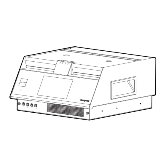
System Components The following photos illustrate the Vertex™ VC4 System views, ports, connections and controls. Overview 1.Cover of Chemcassette® 2.Supply reel 3.Tape guide roller 4.Optics block 5.Status LED 6.Alarm Buzzer 7.HMI Display 8.Needle valve 9.Air filter 10. Keyboard 11. Handle 12. - Page 13 Back view 1. Alarm wire panel knockouts 2.Line power in 3.Fuse 4.Power switch 5.Sample inlets and exhaust 6.Current loop knockout 7.Ethernet port 8.COM port 9. Cooling fan Vertex VC4 System User Manual...
- Page 14 IO Panel I/O panel (cover removed) 2. IO connection identification card Remove the cover of IO panel Vertex VC4 System User Manual...
- Page 15 System Control Unit 1. Industrial Tablet PC 2. USB port 3. Analyzer main board 4. USB disk 5. Keyboard Vertex VC4 System User Manual...
- Page 16 Chemcassette® 1. Chemcassette® directional flow Vertex VC4 System User Manual...
-
Page 17: Sampling System
Sampling System The Vertex™ VC4 is a monitoring center for sampling lines from sample locations. As they apply to the Vertex™ VC4 System, the words point, line and location require definition: • A location is a place to be monitored •... -
Page 18: Chemcassette® Detection System
The system powers up in the same state as when powered down. Data is stored in the module’s memory until the data acquisition computer retrieves it. The Vertex™ VC4 Analyzer module use the Honeywell Analytics Chemcassette® optical detection system. Analyzer module sample and detect a specific gas or family of gases. - Page 19 The microprocessor in the Chemcassette® analyzer module interprets the stain. It then calculates and reports a precise concentration level to Daq PC or external system. Gas concentrations are reported in parts-per-million (ppm), parts-per- billion (ppb) or milligrams-per-cubic-meter (mg/ m Chemcassette® Tapes Chemcassette®...
-
Page 20: Vacuum Pump
Vacuum Pump The pump provides a vacuum source for the transport and sample flow system. The pump exhaust connects to the manufacturing facility central toxic exhaust system. Note: The exhaust line from the Vertex™ VC4 should not exceed 50 feet. The pump is located in the Vertex™... -
Page 21: Control Systems
Control Systems The Vertex™ VC4 control system consists of a central data acquisition computer (DAq), and one analyzer module. Following is a simplified block diagram of the communications path of the control system. The analyzer module is microprocessor controlled and contain non-volatile memory. Vertex VC4 System User Manual... -
Page 22: Data Acquisition Computer
Data Acquisition Computer The data acquisition computer (DAq) is the central processor for the Vertex™ VC4 System. It configures the analyzer, stores data and provides a network interface for data transfer to other computers. System display and operator control is through an on-screen keyboard. Vertex VC4 System User Manual... -
Page 23: Installation
CHAPTER Installation The installation procedure for the Vertex™ VC4 System consists of six steps: 1. Surveying the Installation Site 2. Optional Mounting Method 3. Installing Sample Lines / Filters 4. Installing Pump Exhaust Line 5. Electrical Power 6. Data Acquisition System Installation Step 1: Surveying the Installation Site A survey of the site helps you to make important decisions before installing your Vertex™... - Page 24 Sample Transport Time The shorter the sample line, the shorter the transport time. If monitoring a critical location, it may be desirable to place the monitor near that critical area to reduce sample transport time for that location. Monitor Dimensions Monitor dimensions are important factor in monitor placement.
- Page 25 Installation Drawings Vertex VC4 System User Manual...
-
Page 26: Rack Mounting
Rack Mounting Vertex™ VC4 Rack Kit includes two custom slides and hardware for installation in a customer-supplied standard 19 inch rack. CAUTION Verify power is Off before disconnecting customer I/O board Follow these points when installing the rack mount: 1. Verify proper clearances and dimensions for instrument placement. 2. - Page 27 4. In the recessed position, make sure there is 3-1/4 inch (8.25 cm) clearance for the loop of slack cable as shown in Figure below 5. To slide out the device, press the lever Vertex VC4 System User Manual...
-
Page 28: Installation Step 3: Installing Sample Lines
Installing Sample Line Particulate Filters ⚫ Honeywell Analytics supplies FEP grade Teflon tubing with all new monitors. This tubing is manufactured to our own strict specifications and has been purged of all byproducts of the manufacturing process. On occasions, users have supplied their own FEP type tubing. Should you choose to use your own tubing, be advised that some brands of FEP tubing off-gas small amounts of HF, which can be detected on start up by Honeywell Analytics monitors configured for detecting mineral acids gases (HBr, HCl, HF, NF3). - Page 29 Sample Line Connections To prepare for installation of sample lines, remove the FEP Teflon tubing from the installation kit. The back of the unit includes 5 connections: 4 Sample Inlets (Point legend follows and is in proper sequence.) ⚫ Exhaust Outlet (See Installing Pump Exhaust Line, for connection.) ⚫...
- Page 30 Installing Sample Line Particulate Filters Attach a sample line filter to the sampling end of the line for all locations. CAUTION Excess amounts of dirt in the filters reduces the sample flow, raises sample vacuum and may affect concentration readings of the analyzer. See Filter Compatibility Specifications, to determine the proper filter type to use with each target gas.
-
Page 31: Installation Step 4: Installing The Pump Exhaust Line
Follow the general requirements listed below when installing exhaust lines. The length of the line should not exceed 50 ft. (15 m). If longer distances are required, contact Honeywell Analytics. Do not crimp exhaust lines or place them in an area where weight could collapse the tubing or bend them to less than a 12 in. -
Page 32: Installation Step 5: Electrical Power
Installation Step 5: Electrical Power The Vertex™ VC4 requires a dedicated AC power line. Configurations include: • 110 VAC; 50 or 60 Hertz; 3 amp • 220 VAC; 50 or 60 Hertz; 2 amp Plug the line into a dedicated outlet having sufficient amperage capacity. Line voltage should fluctuate no more than ±... -
Page 33: Installation Step 6: Data Acquisition System
Installation Step 6: Data Acquisition System The data acquisition computer or DAq is the main computer in the Vertex™ VC4 System. The Vertex™ VC4 System can be connected to an external Ethernet network at the port shown. Main computer and Keyboard External Network Connection The ferrite is supplied with the Vertex™... -
Page 34: Installation Step 7: Wiring Alarm Relays
Installation Step 7: Wiring Alarm Relays WARNING Use caution when servicing fuses or terminal blocks. Power to contacts is supplied externally. Relay Contacts The Vertex™ VC4 has 14 form C, single-pole, double-throw relays that activate external alarm devices. Contacts are available for each circuit to accommodate installation of external devices. - Page 35 Ratings To ensure reliable contact operation, the following limits must be observed: 0.1 to 2.0 amps ⚫ @5-24 VDC or ⚫ @5-120 VDC ⚫ CAUTION The alarm relay has a minimum load requirement of greater than 5V and 100 mA. For reliable relay operation, ensure the alarm circuit meets these requirements.
-
Page 36: Installation Step 8: Wiring Current Loop (4-20 Ma Output)
Installation Step 8: Wiring Current Loop (4-20 mA Output) Each current loop output produces a current which varies linearly from 4 to 20 mA as the concentration of gas varies from zero to full scale concentration. The gas concentration for 20 mA full scale defaults to the full scale of the gas. Furthermore, the Vertex™... -
Page 37: Device Operations
Learn the Honeywell Vertex™ VC4 system start-up sequence and how to configure the analyzer module for specific gas locations. Honeywell Analytics loads all software on the DAq at the factory. You need to configure each point for the target gases at your facility. -
Page 38: Power Up
Power Up Use the rocker switch on the right rear of the unit, above the power cord, to turn on power to the Vertex™ VC4. 1. Open the rack door. 2. Open the touch screen door. 3. Turn on the rack power switch. 4. -
Page 39: Start Program
Start Program Upon power-up, the HMI PC automatically starts Ubuntu (Linux) and loads the Vertex™ VC4 HMI program. After the startup sequence, the Vertex™ VC4 HMI main screen opens as below. The start-up time may take several minutes, and the default user is Viewer (R3). NOTE Any time the Vertex™... -
Page 40: Create A Configuration Profile
Create a Configuration Profile The configuration profile stores all of the monitor settings in a single file on the hard drive. Configuration profiles include system level information, point settings and analyzer information. 1. From the main menu, go to System Manager > Profile Manager. Then you’ll see the bellowing page. - Page 41 2. Tap the Add profile button Vertex VC4 System User Manual...
- Page 42 3. In the Add new profile page, enter a profile name, and then you can start to edit the profile. 4. You can edit or modify values such as: Configuration of Analyzer & Points and Notification of Service Due, Events, Timeout, Serial comm, Database through pressing the tabs to access the relative pages. Vertex VC4 System User Manual...
- Page 43 5. After configuration is completed, tap SAVE button or tap back button to complete the Creating Profile process. 6. When you tap the back button , there are several options for the profile you just edit, you can choose to SAVE or DON’T SAVE the profile. Vertex VC4 System User Manual...
- Page 44 7. Tap SAVE & INSTALL whether you want to install this new profile in the system. If you do not want to install this project, tap SAVE AS and enter a profile name 8. To install another profile, you can select a profile in the list on the left side, and then tap the install button to complete installation Vertex VC4 System...
- Page 45 Analyzer & Points Tap on the Analyzer config EDIT button. Activate the Analyzer configuration, select the gas family. Vertex VC4 System User Manual...
- Page 46 Duty Cycle This function allows the user to extend the duration of the tape advance interval. This is useful in applications in which a background level of gas is expected in normal operation. This interval can be configured for up to fifteen minutes. When in monitor mode, if the detector reaches its maximum concentration for that window, it will not advance tape and stays at current window until the duty cycle expires.
- Page 47 Units Select to display concentrations in milligrams per cubic meter. If this option is not selected, Vertex™ VC4 displays concentrations in parts-per-million (ppm) or parts-per-billion (ppb). Select a target gas for the point and enter the gas location of the place where gas is sampled. A Tag Name can be set for the point also.
- Page 48 Non-Zero Warning When this option is ON and non-zero gas concentration is detected, an informative event will be recorded and non-zero warning status will be reported to DAq. The point with non-zero warning will blink in green. Alarm Alarm levels can be selected from the preset or entered. When custom is selected, alarm levels are edited manually. Vertex VC4 System User Manual...
- Page 49 Copy Point Configurations When multiple points are configured in same way, an operator can configure one point and copy it to other points to save time. Tap on the APPLY TO OTHERS button. Vertex VC4 System User Manual...
- Page 50 Service Due Notification of service due is ON, the analyzer will generate a maintenance fault when the maintenance service is overdue. When this option is OFF, an informative event will be recorded instead Events Vertex VC4 System User Manual...
- Page 51 All events require to click Ack When selected, all gas alarms, and fault events will not be removed from the event list until an authorized user acknowledges the event. Non-Latching Gas Alarm A latching gas alarm activates when a gas concentration reaches a level 1 or level 2 alarm setting. The latching gas alarm remains until an authorized operator resets the alarm.
- Page 52 Alarm Delay When Alarm delay is ON, a gas alarm will be reported when a gas concentration reaches a level 1 or level 2 alarm setting and stays for more than alarm delay time. If the gas concentration drops below the alarm setting in less than alarm delay time, the gas alarm event will not be reported.
- Page 53 Report Maintenance Fault Select OFF to disable maintenance faults. When this option is OFF, the Analyzers will not generate maintenance faults. Instead informative events will be recorded. Stale CC Fault When this option is ON and Chemcassette® is nearing its expiration date, the maintenance fault will be generated. Accelerated CC Usage Fault When this option is ON and Chemcassette®...
- Page 54 Select On and enter a timeout up to displayed minutes or select OFF to disable the maintenance fault. Set Serial Comm The configuration of Modbus RTU can be configured in Serial Comm Settings. Vertex VC4 System User Manual...
- Page 55 Set Database The retention period of logged gas data and event records can be configured in Database Settings. The default setting for the retention period of the logged gas data is 90 days. Vertex VC4 System User Manual...
- Page 56 Export/Import a Profile To export a profile, plug in USB flash drive in the DAq. Select the profile in the list and tap EXPORT to export it to USB flash drive Select the location where the profile will be exported and tap NEXT Vertex VC4 System User Manual...
- Page 57 Enter a profile name and tap EXPORT and profile exporting will be completed. Vertex VC4 System User Manual...
- Page 58 To import a profile from USB flash drive, tap IMPORT Select the profile in the Import Profile window and tap NEXT. Selected profile will be imported and shown in the profile list of Profile Manager Vertex VC4 System User Manual...
-
Page 59: Login And Logout
Login and Logout To protect the integrity of the system, the Vertex™ VC4 System classifies the access levels as a viewer, an operator and an administrator. If you require access to a protected menu, you must log in under a user role with permission to use that menu. - Page 60 4. To log out tap on the user role icon at the bottom of the main menu and select Log Out. NOTE Default user ID and password are Admin / Admin for an administrator role and Operator / Operator for an operator role.
-
Page 61: Create A New User
Create a New User Administrator can add a new user and assign an appropriate role to the user account. 1. From the main menu, go to System Manager > Security 2. To add a new user, tap on the ADD button Vertex VC4 System User Manual... - Page 62 3. Type a username, password according to the password complexity and select an appropriate role to the user Vertex VC4 System User Manual...
-
Page 63: Edit User Accounts
Edit User Accounts Administrator can edit user counts and change the user role and password. 1. From the main menu, go to System Manager > Security To edit users, select the target user in the list and tap on the EDIT USERS button . - Page 64 2. User role and password for the user can be changed by an administrator. 3. Alternatively, logged user can change one’s password by tapping on the Change password button. Vertex VC4 System User Manual...
- Page 65 NOTE The modified user password needs to log in again to take effect. Vertex VC4 System User Manual...
-
Page 66: Set Login Timeout
Set Login Timeout Administrator can set login timeout to log out the account automatically, if there is no operation within the set time. 1. From the main menu, go to System Manager > Security NOTE The setting Timeout period needs to log in again to take effect. Vertex VC4 System User Manual... -
Page 67: View Overview Status
View Overview Status View Overview status of the Vertex™ VC4 such as analyzer status, pump status and point status of up to 4 points 1. In the left navigation panel, tap OVERVIEW 2. Analyzer status is shown with gas family configured to the Analyzer The point status are represented graphically as below depending on the status and configuration. - Page 68 To view service due of the Vertex™ VC4, tap on the at the upper right of the Overview screen. Service due will be shown graphically such as remaining CC tape life, remaining days to Optic cleaning and remaining days to filter replacement. Vertex VC4 System User Manual...
-
Page 69: View System Status
View System Status Review status of 4 points, Chemcassette® life, Optic block status, flow status, filter status, Pump status and I/O setting. 1. From the main menu, tap OVERVIEW 2. Point status such as gas name, gas concentration, measurement unit, location tag and point status will be displayed. -
Page 70: View Detailed Analyzer Information
View Detailed Analyzer Information 1. In the left navigation panel, tap OVERVIEW 2. Tap on the Analyzer button The Analyzer Information window displays the Serial No. and the Profile ID. 3. Tap View Details. The detailed info is displayed. Use the arrow button to expand or collapse the contents. Scroll downward to view the entire contents. - Page 71 4. Optional Step to export the detailed profile information, tap Export. Select a USB port to export the information, and then tap NEXT. In the File name field, enter a file name for the export process, and then tap NEXT. Follow the instruction to complete the process. Vertex VC4 System User Manual...
- Page 72 Vertex VC4 System User Manual...
-
Page 73: View Detailed Point Data
View Detailed Point Data Review point status, alarm settings and trend chart of the selected point. The point status includes gas name, gas concentration, measurement unit and live chart of the point. In the Point Detailed Status screen, alarm settings and k-factor are displayed along with real time gas concentration. - Page 74 4. Tap the back button to return to the Overview screen. Vertex VC4 System User Manual...
-
Page 75: Acknowledge Notifications
Acknowledge Notifications Acknowledge and clear gas alarm, Instrument faults, and Maintenance faults notifications. 1. From the upper right side of the main screen, tap on any of the notification icons of to view notification details. The selected icon is highlighted with a blue underline. - Page 76 Vertex VC4 System User Manual...
-
Page 77: Maintain The Pump Close To Due Date
Maintain The Pump Close to Due Date Service is required when pump uptime is reaching to the end. Normally, recommend to maintain the pump every 6 months. 1. In the Pump maintenance page, if runtime is due or there are some faults, the color of texts would turn into yellow, otherwise, when the pump status is good, the color is white. - Page 78 3. Tap CONFIRM to reset the counted uptime days. The highlighted uptime resets to zero. 4. Optionally the temperature status in the pump module and high pressure status at exhaust line can be checked. When there is any issue in temperature and exhaust pressure, the text of Temperature and Exhaust tubing will be highlighted in yellow.
-
Page 79: Turn A Pump On And Off
Turn a Pump On And OFF You can turn ON or OFF a pump when all the Analyzer is out of the monitor mode. 1. In the Pump Maintenance window, tap TURN ON PUMP or TURN OFF PUMP as needed. Vertex VC4 System User Manual... - Page 80 Vertex VC4 System User Manual...
-
Page 81: Turn The Monitoring Mode On And Off
Turn the Monitoring Mode On and OFF 1. In the left navigation panel, tap OVERVIEW 2. Tap on the Analyzer button to enter to the analyzer detail page. 3. In below page, switch the toggle button of Monitoring mode can setup the analyzer either as Monitor or as Idle. -
Page 82: Open The Optic Gate
Open the Optic Gate 1. In the left navigation panel, tap OVERVIEW 2. Tap on the Analyzer button to enter to the analyzer detail page. 3. In below page, switch the toggle button of Optic gate into Open. NOTE The Optic gate is closed when Monitoring mode is on. Vertex VC4 System User Manual... -
Page 83: Advance The Chemcassette® Tape
Advance the Chemcassette® Tape 1. In the left navigation panel, tap OVERVIEW 2. Tap on the Analyzer button to enter to the analyzer detail page. 3. In below page, tap ADVANCE TAPE button next to Advance tape. Or tap LONG ADVANCE button, Chemcassette®... -
Page 84: View Optic Status
View Optic Status View Optic status of the selected analyzer such as optic drive status, optic block status and optic cleaning due. 1. In the left navigation panel, tap OVERVIEW 2. Tap on the Optic button to enter to the optic detail page. 3. - Page 85 Vertex VC4 System User Manual...
-
Page 86: Adjust The Optic Block
Adjust the Optic Block 1. In the left navigation panel, tap OVERVIEW 2. Tap on the Optic button to enter to the optic detail page. 3. In the Optic Block page, tap ADJUST OPTICS, and then tap CONFIRM. Follow up on screen instructions and when Next button appear, tap NEXT button to continue. - Page 87 Vertex VC4 System User Manual...
- Page 88 Vertex VC4 System User Manual...
- Page 89 5. Optional Step. Tap the RESET DUE DAYS button to reset the configured Optic cleaning interval. Vertex VC4 System User Manual...
-
Page 90: Test Optic Block
Test Optic Block 1. In the left navigation panel, tap OVERVIEW 2. Tap on the Optic button to enter to the optic detail page. 3. In the Optic Block status screen, tap on the TEST OPTICS button Prepare a tape leader and follow the instruction to test optic block. The whole process is manual operation. - Page 91 4. Insert the white tape leader to the Optic block carefully to make sure white tape leader is placed and well aligned Optic block and tap on the NEXT button. Vertex VC4 System User Manual...
- Page 92 5. Insert the light gray tape leader to the Optic block carefully to make sure light gray tape leader is placed and well aligned Optic block and tap on the NEXT button. 6. If color change (stain development) is detected by Optic blocks, the Analyzer computes gas concentrations and generate a gas alarm1.
- Page 93 7. Insert the dark gray tape leader to the Optic block carefully to make sure dark gray tape leader is placed and well aligned Optic block and tap on the NEXT button. 8. If color change (stain development) is detected by Optic blocks, the Analyzer computes gas concentrations and generate a gas alarm2.
- Page 94 9. Take out the test leader, re-install the chemcassette® tape and tap on the NEXT button. 10. Choose a mode for this analyzer, MONITOR or IDLE. Vertex VC4 System User Manual...
-
Page 95: Leak Checking Sample Lines
If the sample point passes the test with the back port plugged, the leak is somewhere in the sample line and the line must be replaced. If the sample point fails the leak check procedure with the back inlet port plugged, contact Honeywell Analytics for assistance. Vertex... -
Page 96: Adjust The Flow Rate
Adjust the Flow Rate With the system vacuum level set, the unit is now ready to adjust flow for all the points. Release analyzer from the cabinet, and you can find the needle valves on the analyzer. • In the left navigation panel, tap OVERVIEW •... - Page 97 on the graph. • Once the flow reaches the target flow rate of 200 ± 10cc/min, the bar will change color to green. • Repeat for all points that are out of range. • Once complete, press STOP FLOW. This will stop for the flow, and the pump will turn off. Vertex VC4 System User Manual...
-
Page 98: Sample Line Filter Replacement Counter
Sample Line Filter Replacement Counter 1. In the left navigation panel, tap OVERVIEW 2. Tap on the Flow Rate button to enter the flow detail page. Either the regular replacement window highlighted in green or the expired time window highlighted in yellow is displayed. -
Page 99: 2Ma Fault Operation
2mA Fault Operation Use the 2 mA fault operation function to enable a 2 mA signal on the current loop that indicates when an instrument fault occurs. The VERTEX™ VC4 differentiates between a power loss and a fault by dropping the signal to 0 mA after a power loss or CPU failure and 2 mA when an instrument fault occurs. -
Page 100: Calibrate Current Loop
Calibrate Current Loop The Calibrate Current Loop function calibrates the external analog devices connected to the module by generating a 2 mA to 20 mA analog signal from each individual point. If 2 mA fault indication is disabled, then the minimum current will change from 2 mA to 4 mA. - Page 101 Selecting Signal Levels – Automatic Ramping Selecting Signal Levels – Step Vertex VC4 System User Manual...
-
Page 102: Tune Current Loop
Tune Current Loop The Tune Current Loop function allows you to adjust the VERTEX™ VC4 monitor’s output level so that it is correlated from zero to full scale with a driven device (an instrument used to monitor 4-20 mA output). This is necessary only if new current loop hardware has been field installed. - Page 103 9. Optional, user can tap LOAD DEFAULT button to reload the default DAC endpoint value to adjust 4 mA or 20 mA output. NOTE This should not be performed without a known accurate external ammeter. Vertex VC4 System User Manual...
-
Page 104: Set Relay State
Set Relay State Select the state of the relay contacts to either energized or de-energized. The default condition is de-energized for all relay contacts except the watchdog relay, which remains energized as a failsafe precaution in the event of power loss. -
Page 105: View And Export The Events History Listed By Time
View and Export the Events History Listed By Time 1. In the left navigation panel, tap Event History 2. Tape the filter button, there are more filter types can be seleceted. Vertex VC4 System User Manual... - Page 106 3. Tape the button, you can fliter the events by time range. Vertex VC4 System User Manual...
-
Page 107: Export The Events History
Export the Events History 1. Insert a USB flash drive to Vertex™ VC4 HMI PC. 2. Tap the Export icon to export the event histories to CSV file. 3. Export event history screen will pop up asking the user to enter a file name. Type a file name and touch NEXT button. - Page 108 4. Select a USB drive to export the event histories and touch NEXT button. Once exporting is complete, the "Exporting is completed" screen will be shown as below. It may take several minutes depending on number of events to be exported. Vertex VC4 System User Manual...
- Page 109 Vertex VC4 System User Manual...
-
Page 110: View System Version Information
View System Version Information Version Manager shows version information of Vertex™ VC4 system components such as Analyzer, DAq and IO Panel. The version information includes FW version, HMI application version, part numbers, and serial numbers. 1. From the main menu, go to System Manager > Version Manager 2. - Page 111 3. In Version Information tab, the summary of version information is shown and can be exported to a CSV file. Tap on the EXPORT button and enter file name to export a version Vertex VC4 System User Manual...
- Page 112 Vertex VC4 System User Manual...
-
Page 113: Fault/Alarm Test
Fault/Alarm Test Vertex™ VC4 system can simulate Fault and Alarm to test system. Fault Test Use the Fault Test to simulate Maintenance Fault and Instrument Fault. 1. From the main menu, go to System Manager > TEST 2. In Fault Test tab to select Fault Type, Maintenance Fault or Instrument Fault 3. - Page 114 NOTE The fault test simulates an actual fault condition and the Vertex™ VC4 System activates fault relays. Notify appropriate personnel that you plan to conduct a fault test Alarm Test Use the alarm test to simulate a gas concentration for any analyzer 1.
- Page 115 NOTE The alarm test simulates an actual alarm condition and the Vertex™ VC4 System activates all alarm relays. Notify appropriate personnel that you plan to conduct an alarm test. Vertex VC4 System User Manual...
-
Page 116: View Help File
View Help File 1. In the left navigation panel, tap HELP 2. Navigate the help using navigation panel on the top of help. Vertex VC4 System User Manual... -
Page 117: Update An Analyzer Firmware
Update an Analyzer Firmware To update an analyzer firmware, USB flash drive with an update file should be prepared. Please contact Honeywell Analytics to get the latest update SW files. 1. From the main menu, go to System Manager > Version Manager 2. - Page 118 6. Tap on the Next button. Select the analyzers you are going to update firmware. Tape on the Next button, the Stop monitoring screen will pop up asking a user to confirm it. Vertex VC4 System User Manual...
- Page 119 Vertex VC4 System User Manual...
- Page 120 7. Tap on CONFIRM button and firmware update will be started. The firmware update progress has two steps. The first step is that the update file is being transferred to Analyzers, and the second step is that the Analyzers are updating the firmware.
- Page 121 Vertex VC4 System User Manual...
- Page 122 8. Tap on Done button when Firmware update is done with green smile face and it moves back to Version Manager screen with updated version information. Vertex VC4 System User Manual...
-
Page 123: System Shutdown
System Shutdown Failure to properly shut down the Vertex™ VC4 could result in system file corruption 1. Go to Runtime Operation and stop monitoring mode. 2. Go to Settings -> System Switch and touch System Shutdown Touch Proceed on the confirmation screen Vertex VC4 System User Manual... - Page 124 4. Once the HMI system is off, set the power switch to "Off" Vertex VC4 System User Manual...
-
Page 125: Maintenance
CHAPTER Maintenance This section describes routine maintenance procedures. Maintenance Schedule Component Frequency Sample line filters (end of line) 3-6months 9-24 months operation Pump vane replacement per pump Particulate Filters 3-6months Acid Scrubber Filter 6 months Optics Cleaning 1 year or as needed System File Maintenance 1 year or as needed Vertex... -
Page 126: Replace The Chemcassette
Replace the Chemcassette® Change the Vertex™ VC4 Chemcassette® tape for any of the following reasons: Scheduled end-of-tape service ⚫ Low Chemcassette® warning ⚫ Chemcassette® has expired ⚫ End of Chemcassette® ⚫ 1. In the left navigation panel, tap OVERVIEW 2. Tap on the Chem-C button to enter Chemcassette® page. 3. - Page 127 5. The tape replacement procedure gets started. The Analyzer is released, and the Optics gate opens. 6. When you see this page, pull out the Analyzer and remove old Chemcassette® tape. Vertex VC4 System User Manual...
- Page 128 7. Route the Chemcassette®tape through Optics blocks and guide rollers. Vertex VC4 System User Manual...
- Page 129 8. Install the leader tape into slot of the pick-up reel. When the Chemcassette® leader is installed, adjust the leader tape by verifying the optics block should be placed between the two “ALIGN” marks on the tape leader. The alignment is essential to adjust and verify the Optics module before gas monitoring.
- Page 130 10. When new Chemcassette®is installed correctly, tap NEXT. 11. The Analyzer reads the RFID tag on the Chemcassette® tape and shows the tape information. Check the Chemcassette® information and if no issue appears, tap NEXT 12. If the Chemcassette® is a brand-new tape, the Optics module is adjusted and verified while advancing the Chemcassette®...
- Page 131 13. After completing the Optics adjustment/Verification, either turn the analyzer into monitoring or leave them as idle by tapping MORNITOR or IDLE. Vertex VC4 System User Manual...
-
Page 132: Replace Pump
Replace Pump The Vertex™ VC4 System includes one vacuum pumps. You may replace a defective pump with a new good one. NOTE You may replace a pump only when the system is power off. Do not replace an operating pump. WARNING The pump to be disconnected must be off 1. - Page 133 4. Unscrew six screws on rear cover of VC4 and disassemble rear cover. 5. Loose screw nut 1 and disassemble screw nut 2 and ground wire from screw bolt 2. 6. Disconnect tube from pump’s quick connector fitting. Slide out pump assembly on proper location and then take out pump assembly.
- Page 134 7. Unfasten 5 nuts (4 nuts for fixing pump, one for fixing capacitor) , disassemble ground wire and capacitor and pump from bracket. 8. Reinstall new pump and capacitor into bracket and assemble ground wire and fasten 5 nuts. 9. Repeat steps in reverse order to finish the pump replacement. Vertex VC4 System User Manual...
-
Page 135: Replace Internal Filters
Replace Internal Filters The Model VERTEX™ VC4 will use one filter block. The filter block is keyed to fit only one way into the instrument. Filter block Filter block handle Gray Ring Particulate Filters Acid filter 1. Open VC4 cover to the servicing position. 2. -
Page 136: Fuse Replacement
Fuse Replacement The Vertex™ VC4 is protected with a fuse located on the rear panel beneath the power cord. To replace the AC line fuse, 1. Unplug the power cord. 2. With a slotted screwdriver, carefully pry the fuse cap outward. 3. -
Page 137: Orifice Inspection, Cleaning & Replacement
Orifice Inspection, Cleaning & Replacement The orifice is protected by filter. In general, there is no need to replacement or cleaning. In the event that a particle or foreign object makes it past the end of sample line filter, the orifice is clogging and slowing down sample transport times, you may clean or replace orifice. - Page 138 4. Once removed, cleaning the cartridge for any debris on the surface. (check orifice on the end of cartridge.) 5. Replace the cleaned or new orifice into the cavity it came from, check that the orifice is fully installed into the manifold and Align the slot on the back side of the orifice to be horizonal.
-
Page 139: Clean The Optics
Clean the Optics Clean Chemcassette® optics annually or whenever optics verification error occurs. Compressed air is required or per the locations PM schedule. 1. Make sure the Analyzer is out of Monitor Mode. 2. Open the Optics Block Gate. 3. Remove the Chemcassette® by releasing and pulling out the analyzer. 4. -
Page 140: Clean The Touchscreen
Clean the Touchscreen Clean the touch screen display with a lightly moistened towel. Do not spray cleaner directly onto the glass. Excess liquid will run down the screen and interfere with operation. Reference your touch monitor manual for any additional information. Vertex VC4 System User Manual... -
Page 141: Additional Information
CHAPTER Additional Information Learn from about strategic information related to the Honeywell Vertex™ VC4 Detector. Specifications Module 1904C-1000, 110V ± 10% VAC 50/60Hz Part No. 1904C-1002, 220V ± 10% VAC 50/60Hz OVERALL SYSTEM DIMENSION Size 8.7“(H) x 17”(W) x 17.9“(D) (22 x 43 x 45cm ) (Table mount) 8.7“(H) x 17.5”(W) x 17.9“(D) (22 x 45 x 45cm) (Rack mount) - Page 142 Relay Outputs Relay contacts (500mA minimum) 2A @ 120VAC, form C contacts. Programmable low and high levels, maintenance, watch dog, energized or de-energized, latching or nonlatching Current Loop 4-20mA isolated (2-4mA range available for fault indicators) Outputs (per Point) SECURITY Role-based access control Support HTTPS CERTIFICATION AND SPECIFICATION...
-
Page 143: Detectable Gases
Detectable Gases Vertex™ VC4 System Chemcassette® analyzer are continuous monitoring instrument. The initial analysis period listed in the following table varies based on the programmed alarm levels. This period is valid only after the system pulls a new Chemcassette® window. Increasing the programmed alarm levels will decrease the initial sample period. For accurate detection, gas must be present at sufficient levels and durations. - Page 144 Initial Analysis Family CC Name (P/N) Table Gas Name Range Alarm Setting Time to 1TLV alarm @ 2TLV con- Default Default Period centration, 10ft sample line Alarm Alarm (second) Level 1 Level 2 Boron Trifluoride XP4 0.04 0.05-0.99 ppm <100 sec (Alarm @0.1ppm with 0.2ppm BF3 0.1 ppm 0.05 ppm 0.05 ppm...
-
Page 145: Maintenance Faults
Initial Analysis Default Default Alarm Time to 1TLV alarm @ 2TLV con- Period Family CC Name (P/N) Table Gas Name Alarm Alarm Range Setting centration, 10ft sample line (second) Level 1 Level 2 0.05-0.24 ppm 0.04 0.25-0.49 ppm <40 sec (Alarm @ 0.5ppm with 1ppm Cl2 gas) Chlorine (Cl2) 0.1 ppm 0.05 ppm... - Page 146 Sample line too long or ID too small Check nut on the optic block Poor gate seal Contact Honeywell Analytics Service Flow is 70 cc/min less than nominal Supply vacuum insufficient (less than 7"Hg) Plug pneumatic connector in unused slots Exhaust tubing restricted Service or switch pumps...
- Page 147 Possible Cause Resolution *Reserved Clean optics. Optic block dirty Optics Block Dirty Contact Honeywell Analytics Service. - Cleaning Required Optic block is aged Replace optics block Reload Chemcassette® and recalibrate using leader Tape leader installed improperly End of line filter clogged...
- Page 148 Locate source of background gas Ethernet initialization failed Reboot the analyzers. Failed load the driver, Electronic problem Contact Honeywell Analytics Service. File system of Analyzer is corrupted File system corrupted Contact Honeywell Analytics Service Optics blocks have different software versions Program update done incorrectly Reload program to both optics blocks.
-
Page 149: Instrument Faults
Check motor operation using Maintenance, Analyzer Operations, Open Gate, or Close Gate Check motor connections to sensor interface PCB in analyzer Motor does not operate Gate motor driving failure Check sensor connection on PCB Contact Honeywell service Bad sensor or cable Poor grounding Replace Analyzer, Contact Honeywell service... - Page 150 Optics LED not properly calibrated Perform Load CC Operation to recalibrate Optics drive unusually low Optics board defective Replace Analyzer, Contact Honeywell service Analyzer CPU defective Replace Analyzer, Contact Honeywell service Optics LED not properly calibrated Perform Load CC Operation to recalibrate...
- Page 151 Perform Load CC Operation to recalibrate to insufficient optical signal LED degradated Replace the optics block Optics board defective Replace Analyzer, Contact Honeywell service Chemcassette® leader not tight or improperly positioned during white to Reload Chemcassette® light gray calibration Bad RFID tag Load new Chemcassette®...
- Page 152 Line voltage issue Replace pump, Contact Honeywell service Pump failure Contact Honeywell service Circuit breaker tripped Check tubing and fitting in system, Contact Honeywell service Pump failure Leakage in system Check IO panel cabling Cable issue Reboot the IO panel module. Contact Honeywell service.
-
Page 153: Information Events
Information Events The Vertex™ VC4 System enters informational and other non-fault events into the event history database. These do not require any action by the user. Use the event history to check the status of the instrument. Event ID Description 2001 Analyzer Powered Up 2002... - Page 154 Event ID Description 2021 Reset filter replacement counter 2022 Reset optics cleaning counter 2023 Reset pump maintenance counter 2024 Time changed. Az clock out by >30 seconds 2025 The analyzer rebooted by watchdog 2026 A new Chemcassette® was installed 2027 Mon stopped for no enabled points 2028 Az Button Resets Alm&Flts...
- Page 155 Event ID Description 2044 Imported license file successfully 2045 Rejected license file 2046 Failed to verify update file 2047 Line integrity test characterized 2048 Line integrity test performed 2049 Az lacks LIT option (LIT option not purchased) 2050 Alarm/Fault Reset Request 2051 Reset All Alarms and Faults 2052...
-
Page 156: Manual Analyzer Override
Manual Analyzer Override The Vertex™ VC4 Analyzer is equipped with a Manual Override button in the event the communications to the Vertex™ VC4 Data Acquisition (DAq) computer halts. This button activates only when the communications has completely ceased. There are cases where the DAq appears to be “frozen” or “locked-up” (no response from the keyboard or any user invoked actions after a few moments) while in reality this is not the case. - Page 157 4. Approximately 20 seconds after the Ethernet Cable has been disconnected, the Analyzer will recognize that it has lost communications with the DAq and activate the “Manual Override” button. The LED’s on the front of the Analyzer will flash to show a Maintenance Fault per the LED status flash pattern. To reset faults and alarms press and hold button for 1-3 seconds.
-
Page 158: Fix An Unresponsive Vertex™ Vc4 Touch Screen
Fix an Unresponsive Vertex™ VC4 Touch Screen Completely resetting the computer can resolve many issues that cause a frozen/unresponsive screen. Follow these steps to perform a hard reset: 1. Remove any USB devices from the USB ports of the HMI PC if non-default USB devices were inserted. The USB connection from touch screen should remain 2. -
Page 159: Filter Compatibility
Filter Compatibility When monitoring non-corrosive target gases, use filter type A, (P/N 780248), a sample line dust/ particulate filter. For monitoring corrosive gases, such as chlorine (Cl ), hydrogen fluoride (HF), hydrogen chloride (HCl), and hydrogen bromide (HBr), sample lines in a dusty environment or for outdoors, use filter type B, (P/N 1830- 0055), or type C, (P/N 1991-0147) filter assembly for corrosive gases. - Page 160 Hydrogen Fluoride Filter Type Filter Type Filter Type Symbol Gas Name HF-LL Hydrogen Fluoride - Low Level Hydrogen Selenide Nitrogen Dioxide COCI Phosgene COCI /- HL Phosgene - High Range Phosphine Silane Sulful Dioxide Tetrakis Dimethylamino TDMAT Titanium Vertex C System User Manual...
-
Page 161: Replacement Parts & Consumables
Replacement Parts & Consumables Consumables Chemcassette® XP6-VC4 AMINES /AMMONIA CHEMCASSETTE 1904-9309 XP6-VC4 HYDRIDES CHEMCASSETTE 1904-9300 XP4-VC4 MINERAL ACIDS CHEMCASSETTE 1904-9310 VC4 FLUORINE CHEMCASSETTE 1904-0220 XP4-VC4 PHOSGENE CHEMCASSETTE 1904-9307 VC4 Sulfur Dioxide CHEMCASSETTE 1904-0552 VC4 HYDROGEN CYANIDE CHEMCASSETTE 1904-0222 XP-VC4 CHLORINE-II CHEMCASSETTE 1904-0560 XP4-VC4 CHLORINE CHEMCASSETTE 1904-9308... - Page 162 Spare Part Number 1/4 FEP TUBING KIT (400 ft roll) F15-1554-001 1/4 FEP TUBING KIT (1000 ft roll) F15-1558-001 Equal Straight Connector KIT,1/4 F15-1282-001 Pump Diaphragm kit, 110AVC F15-1268-001 Pump Diaphragm kit,220VAC F15-1269-001 Pump Repair Kit , 60/50 Hz F15-1270-001 Pump inlet tube kit F15-1283-001 1/4 elbow fitting 1/8 NPT, KIT...
- Page 163 Spare Part Number SV KIT,STEPPING MOTOR ASSY,VERTEX-C F14-7040-001 SV KIT,GATE MOTOR ASSY,VC4 3010-1560-001 SV KIT,BRAKE BLOCK ASSY,VERTEX-C F14-7013-001 SV KIT,SPROCKET/W SCREW,VERTEX-C F14-7002-001 SV KIT,TAPE_GUIDE/W SCREW,VERTEX-C F14-7001-001 SV KIT,TAPE GUIDE SHAFT,VERTEX-C F14-7032-001 SV KIT,4P TUBES SET,VC4 3010-1561-001 SV KIT,TUBE,OPB TO PRE,VC4 3010-1562-001 SV KIT,LED INDICATOR,VC4 3010-1563-001...
-
Page 164: Network Interfaces And Options
Network Interfaces and Options Modbus RTU Enable or Disable ⚫ Baud rate (User Selectable) ⚫ 9600 (Default) ⚫ 19200 ⚫ Data bits ⚫ 7 bits ⚫ 8 bits ⚫ Parity (User Selectable) ⚫ None ⚫ Even (Default) ⚫ ⚫ Stop Bits ⚫... - Page 165 Modbus TCP IP Configuration ⚫ DHCP (Default) ⚫ Static IP: Static IP address, Gateway, DNS ⚫ Modbus TCP/IP Enable or Disable ⚫ Web interface on port 80 ⚫ Enable ⚫ Disable (Default) ⚫ Encrypted web interface on port 443 ⚫ Enable ⚫...
-
Page 166: Hmi Pc Security Considerations
HMI PC Security Considerations In general we provide out-of-box application and install application to single computer so it’s not necessary and not allowed to modify application yourself. Please contact Honeywell service team before any firmware/software updates. In order to protect your data please lock HMI Rack to forbidden touching USB port without permission , keep the key properly. - Page 167 HTTPS Connections When making a connection to the Vertex™ VC4 HMI PC via HTTPS, it will be necessary to accept the certificate. A message like the one using Google Chrome will be shown: Tap on the Advanced button, and select “Proceed to <some IP> (unsafe).” External Network Security Considerations The Vertex™...
-
Page 168: Serial Communications And Options
Serial Communications and Options The rear panels of the VERTEX™ VC4 monitor allows installation of serial interface port. These ports are designed to allow output to other devices, and two-way communication between the VERTEX™ VC4 monitor and another device. There are three serial interfaces available for the VERTEX™ VC4 monitor, each designed for a specific communication application. - Page 169 Set Serial Communication After the networking cabling has been connected to the slave, the slave must be configured to communicate. Configuration is performed with the following sequence 1. In the left navigation panel, tap OVERVIEW 2. Tap on the I/O Settings button 3.
-
Page 170: Remote Alarm Reset Option
Remote Alarm Reset Option The remote alarm reset option provides the ability to reset the VERTEX™ VC4 alarm conditions for any individual point from a remote location. There are two ways to connect the remote reset circuit: • using an external 24V DC power supply •... - Page 171 A schematic of the circuit using External Power Supply Using the VERTEX™ VC4 Monitor’s Internal Power Supply Another method of installing the remote alarm reset circuit utilizes the 24 VDC supply available from the VERTEX™ VC4 monitor. While this method is usable for many applications, there are limitations to consider. CAUTION To ensure the VERTEX™...
- Page 172 If no description of the fault is provided, Honeywell reserves the right to charge an investigation fee. If the product is found to be of “no fault”, Honeywell reserves the right to charge an investigation fee and return same product to buyer after the investigation fee and transport cost are reimbursed in full.
- Page 173 Contact Us India Honeywell Analytics Honeywell International India Pvt. Ltd. Building#1, 555 Huanke Road Zhangjiang Hi-Tech Unitech Trade Center, Sector - 43, Park Pudong New Area Shanghai, China Block - C, Sushant Lok - 1, Tel: 021-80386800 Gurgaon - 122002, Haryana, India...