Table of Contents
Advertisement
Advertisement
Table of Contents

Related Manuals for Honeywell P531


Summary of Contents for Honeywell P531
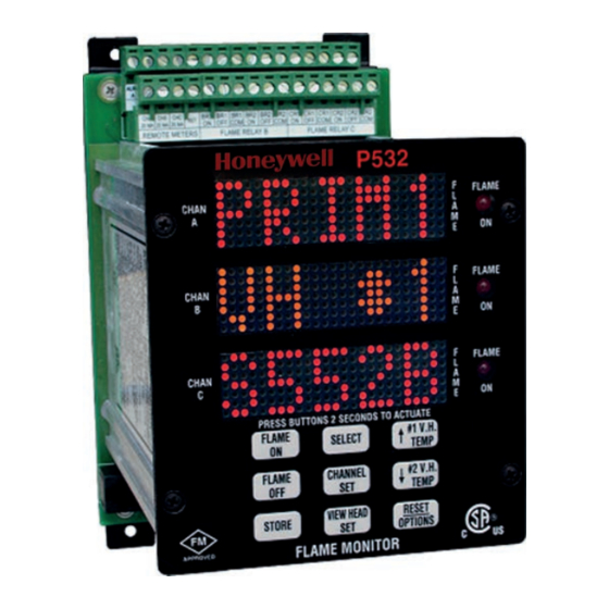
- Page 1 MODEL P531, P532 AND P532UI FLAME MONITOR OPERATING MANUAL...
-
Page 2: Table Of Contents
Alternate Indicator ..........3 Sequence Procedure ........7 Hot Viewing Head Indication ......3 Filter ..............8 Primary / Alternate selection......3 P531 AND P532UI .......... 8 Using the Prim/Alt switch........3 To reset Modbus Prim/Alt register .....3 Display for P531..........8 Non-Advanced viewing heads ......3 Flame On ............ - Page 3 CONTACT INFORMATION......14 Sales and applications support: ...... 14 Factory and repairs: ........14 SPECIFICATIONS ........23 Electrical - Model P531 AC, P532 AC ..... 23 Electrical - Model P531 DC, P532 DC..... 23 Outputs............23 Inputs .............. 23 Serial Communications ........23 Flame ..............
-
Page 4: Design Features Overview
Orange indication for mixture of UV and IR mode. (This is a safety feature). The P531 Signal Processor uses seven discrete The P531 and P532 are compatible with RS-422 and LED’s for display. These include: Modbus protocol, and are field upgradeable with firm- ware download capabilities. -
Page 5: Default Settings
MODELS P531, P532 AND P532UI OPERATING MANUAL There are three menu branches: Alternate – Primary (during configuration) Channel menu has all configuration items asso- The top line will display ALT or PRIM, followed by : ciated with the channel. Channel letter (A, B, or C) Viewing head menu has all configuration items associated with the Viewing head. -
Page 6: Lockout
MODELS P531, P532 AND P532UI OPERATING MANUAL A Bar Graph will be displayed in the last digit of the The configuration is written to Modbus register default display. The Primary configuration will be used for operation if: The graph is proportional to the analog output (20ma) -
Page 7: Replacing Viewing Heads
MODELS P531, P532 AND P532UI OPERATING MANUAL A letter or a number will be displayed after the selec- Toggle primary and alternate viewing head parame- tion indicating the Channel of Viewing head that is ters using the CHANNEL button. being configured or viewed. -
Page 8: Ffrt
MODELS P531, P532 AND P532UI OPERATING MANUAL UV - Only UV will be used for this channel Temperature Alarm (Viewing Head) The appropriate choice must be stored with the The Alarm relays can be configured to energize if a STORE button. -
Page 9: Panel
MODELS P531, P532 AND P532UI OPERATING MANUAL Pushing either the FLAME ON or FLAME OFF will Panel display the current set value in green. The front panel can be disabled for configuration Use the UP and DOWN buttons to change the settings changes by entering a LOCK CODE. -
Page 10: Fit Procedure
MODELS P531, P532 AND P532UI OPERATING MANUAL Fit procedure A rejected gain calibration can occur if fluctuations of signals are detected during calibration or if the Using the channel menu procedure (above) se- signal is such that the gain cannot be determined lect the AUTOMATIC menu branch by toggling automatically. -
Page 11: Filter
P531 AND P532UI ple times can be shortened by pressing a button for one second. However, a minimum of 10 sec- Setup and operation of the P531 is the same as for onds are required.) the P532 when using the P532UI The P532 UI can be connected to and disconnected 10. -
Page 12: Status
MODELS P531, P532 AND P532UI OPERATING MANUAL Status INFRARED GAIN A Green heartbeat (one quick green flash each sec- Analysis of the Electrical and Digital (Software) ond) indicates system normal (self check) gains for the S55xx Viewing Heads. A Red / Green heartbeat (alternating color one... -
Page 13: Installation Notes
Viewing heads are connected to the appropriate termi- nals using the compatibility list. The P531 or P532 Signal processor should be mounted Source Impedance Resistors 470 Ohm ¼ Watt must (using the 4 holes in the corners of the base) to a ver-... -
Page 14: If The Viewing Head Is Not Listed
MODELS P531, P532 AND P532UI OPERATING MANUAL If the viewing head is not listed. If the unit is not restored by cycling the power and set- ting factory defaults: If the viewing head is not listed as a choice in either Record the numbers on the display. -
Page 15: Modbus Protocol
MODELS P531, P532 AND P532UI OPERATING MANUAL MODBUS PROTOCOL Alternate viewing head #1 * 40038 IR Gain VH 1 Legacy Modbus support * 40039 IR Filter VH 1 * 40040 UV Gain VH 1 * 40001 Flame Count (active channel in 522 mode) other wise... - Page 16 MODELS P531, P532 AND P532UI OPERATING MANUAL *40069 *40056 Channel "A” Alternate Read/Write Channel "A” Primary Read/Write * 000001 bit 0 * 000001 bit 0 * 000002 bit 1 * 000002 bit 1 * 000003 bit 2 * 000003 bit 2...
-
Page 17: Modbus Function Support
MODELS P531, P532 AND P532UI OPERATING MANUAL To reset factory defaults for P531 front port write 30064 (RS- 232) *40084 Error code RS422 port only (P531 front port is unde- fined) P531 front panel access only (RS232) *40085 Baud for the RS422 port... - Page 18 MODELS P531, P532 AND P532UI OPERATING MANUAL Channel V H # Sensor Flame Flame FFRT Time Analog Alarm Delay Gain A Prim. A Alt. B Prim. B Alt. C Prim. C Alt. TABLE 1: Temperature Configuration Control Chart 1 IR Gain...
- Page 19 MODELS P531, P532 AND P532UI OPERATING MANUAL FIGURE 1: Wiring and connections S55xx Viewing Head FIGURE 2: Model 700 and 800 viewing head cable connections Page 16...
- Page 20 MODELS P531, P532 AND P532UI OPERATING MANUAL MODULAR SCHEM COLOR COLOR INTERFACE DESCRIPTION POWER CONN. LABEL TYPE A TYPE B LABEL SUPPLY RD (A) FROM PROCESSOR RD (B) FROM PROCESSOR TD (A) PROCESSOR TD (B) PROCESSOR GROUND +12VDC POWER +12VDC CAUTION: The order of the colors in the cable can be TYPE A or TYPE B.
- Page 21 MODELS P531, P532 AND P532UI OPERATING MANUAL FIGURE 4: P532 DC Wiring Diagram Page 18...
- Page 22 MODELS P531, P532 AND P532UI OPERATING MANUAL FIGURE 5: P532 AC Wiring Diagram Page 19...
- Page 23 MODELS P531, P532 AND P532UI OPERATING MANUAL FIGURE 6: P531, P532, P532UI Dimensions Page 20...
- Page 24 MODELS P531, P532 AND P532UI OPERATING MANUAL Viewing Head Setup Channel Viewing Head Selected (Prim/Alt) “1, 2 or 3” Select IR Gain UV Gain IR Filter #2 Temp #1 Temp STORE - - - - - - FLOWCHART 1: Viewing Head Set, Channel Set and Option CHAN SET #1 Temp.
- Page 25 MODELS P531, P532 AND P532UI OPERATING MANUAL Options Select Address Baud Power Reset Panel Parity 0-20 4-20 Default #1 Temp #2 Temp #1 Temp #1 Temp #1 Temp #2 Temp #1 Temp STORE - - - - - - STORE...
-
Page 26: Specifications
MODELS P531, P532 AND P532UI OPERATING MANUAL SPECIFICATIONS Models P531, P532 and P532 UI Electrical - Model P531 AC, P532 AC Primary Input Power 85 – 264 VAC, 47-63 Hz Battery Backup Voltage 24 VDC (voltage above 24 volt will be the power source) -
Page 27: Flame
MODELS P531, P532 AND P532UI OPERATING MANUAL RS-232 (P531 front panel port only) Baud 19200 Parity None Protocol Modbus(RTU) fixed address of 64 Flame Maximum flame detector response time 5 second Minimum flame detector self-checking rate 1 second Maximum flame failure “lock-out” time...