
Related Manuals for Makita XUC04


Summary of Contents for Makita XUC04
- Page 1 INSTRUCTION MANUAL MANUAL DE INSTRUCCIONES Battery Powered Wheelbarrow Carretilla Propulsada a Batería XUC04 XUC05 XUC06 IMPORTANT: Read Before Using. IMPORTANTE: Lea antes de usar.
-
Page 2: Specifications
ENGLISH (Original instructions) SPECIFICATIONS Model: XUC04 XUC05 XUC06 Dimensions When bucket is installed 1,480 mm x 730 mm x 1,030 mm (58-1/4″ x 28-3/4″ x 40-1/2″) (L x W x H) When carrier is installed 1,450 - 1,600 mm x 730 - 1,080 mm x 1,030 mm (57″... -
Page 3: General Power Tool Safety Warnings
Use personal protective equipment. Always SAFETY WARNINGS wear eye protection. Protective equipment such as dust mask, non-skid safety shoes, hard hat, or hearing protection used for appropriate conditions General power tool safety warnings will reduce personal injuries. Prevent unintentional starting. Ensure the WARNING: switch is in the off-position before connecting Read all safety warnings, instruc-... - Page 4 Maintain power tools and accessories. Check Never service damaged battery packs. Service for misalignment or binding of moving parts, of battery packs should only be performed by the breakage of parts and any other condition that manufacturer or authorized service providers. may affect the power tool’s operation.
-
Page 5: Additional Safety Instructions
Never operate the machine in an overloaded Do not operate the machine on excessively condition. Make sure the machine has the proper steep slopes. This reduces the risk of loss of capacity rating for the objects or materials that control, slipping and falling which may result in have to be hauled. - Page 6 15. Use containers and tie-downs to secure loads. When operating the machine near walls, be Loose and/or insecure loads are more likely careful not to get your hands caught between the handle and the wall. to shift which can result in loss of stability and control.
- Page 7 Loading objects When transporting the machine, lock the brake lever, turn the power off, remove the batteries Do not overload objects. When loading and lock key, and fix the machine securely. objects, be sure to follow the instructions and load limits in the manual. Maintenance Since the larger the load, the more difficult it Before storage or attempting to perform...
-
Page 8: Parts Description
Front lamp Bucket causing fires, personal injury and damage. It will also void the Makita warranty for the Makita tool and charger. Tips for maintaining maximum battery life Charge the battery cartridge before completely discharged. - Page 9 XUC05 XUC06 Fig.3 Control panel Beep button Fig.2 Switch trigger Rear lamp Reflector Rear wheel lock Control panel Beep button Handle Battery box Switch trigger Rear lamp Brake lever Rear wheel Handle Battery box Front wheel Front lamp Brake lever Rear wheel Flat bucket Rear wheel lock...
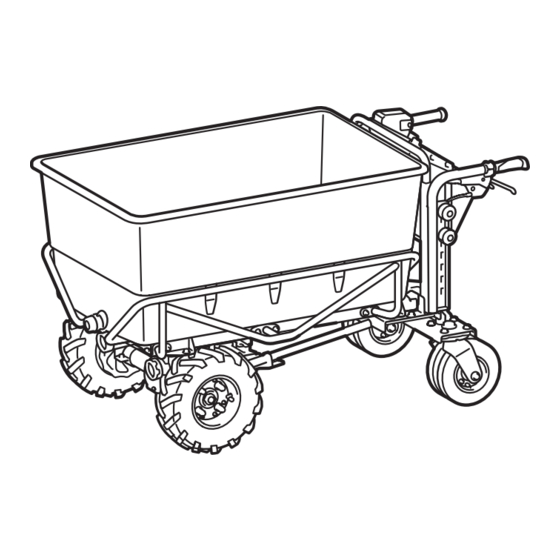
- Page 10 When the carrier is installed CONFIGURATION OF MACHINE When the bucket is installed Fig.5 Carrier Dump unit Base unit Fig.4 When the flat bucket is installed Bucket Dump unit Base unit Fig.6 Flat bucket Base unit 10 ENGLISH...
- Page 11 Insert the pipes of the handle into the dump unit as ASSEMBLY shown in the figure, and then tighten 4 bolts securely. CAUTION: Always be sure that the machine is switched off and the battery cartridges are removed before carrying out any work on the machine.
- Page 12 Place the dump unit on the base unit by holding Attach the cord cover. the dump unit with two people as shown in the figure. Fig.14 ► 1. Cord cover Removing the dump unit To remove the dump unit, perform the installation proce- Fig.12 dure in reverse.
-
Page 13: Installing The Carrier
Removing the bucket Place the stay on the dump unit, and then tempo- rarily tighten the bolts with the front pipe together. Install To remove the bucket, perform the installation proce- the other stay to the dump unit in the same way. dure in reverse. - Page 14 Place the carrier on the dump unit. Assemble the holding frames by tightening 12 bolts. Insert the bolt from the top. Attach the flat washer and spring washer in order to the bolt, and then tighten the nut from the bottom. Tighten the rest of the bolts and nuts in the same way.
-
Page 15: Functional Description
Place the holding frames on the base unit, and Hold the long sides of the flat bucket with two then temporarily tighten 2 bolts at the rear of the people as shown in the figure, and mount the flat bucket machine. -
Page 16: Overload Protection
Close the cover of the battery box. NOTICE: Make sure that the cover of the battery box is closed securely before use. Otherwise, mud, dirt, or water may cause damage to the product or the battery cartridge. Installing the battery cartridge Pull up the lock lever, and then open the cover of the battery box. -
Page 17: Overheat Protection
Overheat protection Checking the battery level on the battery box When the machine is overheated, the machine stops automati- cally and the main power lamp lights up in red. In this case, let the machine and battery cool before turning the machine on again. Overdischarge protection When the battery capacity is not enough, the main power lamp and the corresponding battery indicator blink in red. -
Page 18: Control Panel
Checking the battery level on the Switching the battery cartridge battery cartridge Only for battery cartridges with the indicator Fig.34 ► 1. Indicator lamps 2. Check button Fig.35 Press the check button on the battery cartridge to indi- ► 1. Battery selection switch cate the remaining battery capacity. -
Page 19: Beep Button
Beep button To turn on the machine, lock the brake lever and release the switch trigger, and then press the power When you press the beep button, the beep sound is button. The main power lamp lights up in green. To turn emitted. - Page 20 Fig.40 ► 1. Rear lamp Fig.42 ► 1. Brake lever 2. Lock lever NOTE: The lamps go off if the machine is not oper- ated for a certain period. Adjusting the width of the carrier NOTE: The lamps go off when the power is turned off. NOTE: You can light up the lamps even if the lock key NOTICE: Make sure that the side rails and front...
-
Page 21: Adjusting The Handle Height
Lock the other rear wheel in the same way. Adjusting the handle height Move the rear wheel back and forth or left and right slightly to make sure it is locked. NOTICE: Fix the left and right handles at the same height. -
Page 22: Operation
Neutral change lever Using the level Using the level, you can check if the ground is level. WARNING: Unless absolutely necessary, never disable the electric brake of the machine with the neutral change lever. Since the electric brake of the machine is disabled, the machine may move unintentionally and cause an accident or per- sonal injury. - Page 23 Pull the brake lever to release the lock of the Loading objects brake lever. CAUTION: Before loading objects on the machine, make sure that the machine is turned off and the brake lever is locked. CAUTION: Before loading objects on the machine, make sure that the dump unit is locked.
-
Page 24: Dumping Objects
When loading objects on the carrier, secure the objects Rotate the lock lever of dump unit counterclock- with ropes and tie them down to the rope hooks of the wise to unlock the dump unit. carrier. Fig.60 ► 1. Lock lever Stand at the side of the machine, then hold the handle of the machine with one hand, and then hold the handle of the dump unit with the other hand. -
Page 25: Inspection Before Operation
Draining liquid Inspection before operation Perform the following inspections before operation the machine. CAUTION: Before draining the liquid, be sure • Check that the bolts, nuts, and knobs are tightened firmly. to lock the brake lever. To drain the liquid inside of the flat bucket, loosen and remove the cap of the flat bucket. -
Page 26: Adjusting The Brake
Storage Adjusting the brake Lock the brake lever, and remove the battery cartridges If you feel the brake is not working sufficiently, adjust and lock key. Store the machine in a safe place out of the brake lever. the reach of children. Pull the brake lever to release the lock of the brake lever. - Page 27 Tighten only the fixing nut of the brake lever. Fig.69 ► 1. Fixing nut 27 ENGLISH...
- Page 28 Replacing the tire CAUTION: Before replacing the tires, be sure to unload all objects from the machine. CAUTION: When replacing the tires, wear the gloves. Replacing the tire of front wheel NOTE: When installing the gray tire, install it so that the valve faces outward. Fig.70 28 ENGLISH...
- Page 29 Replacing the tire of rear wheel Fig.71 29 ENGLISH...
- Page 30 Fig.72 30 ENGLISH...
-
Page 31: Troubleshooting
TROUBLESHOOTING Before asking for repairs, conduct your own inspection first. If you find a problem that is not explained in the manual, do not disassemble the machine. Instead, ask Makita Authorized Service Centers, always using Makita replacement parts for repairs. -
Page 32: Optional Accessories
Use of any other accessory or attachment may result in serious per- sonal injury. If you need any assistance for more details regard- ing these accessories, ask your local Makita Service Center. • Carrier •... -
Page 33: Especificaciones
ESPAÑOL (Instrucciones originales) ESPECIFICACIONES Modelo: XUC04 XUC05 XUC06 Dimensiones Con la canasta instalada 1 480 mm x 730 mm x 1 030 mm (58-1/4″ x 28-3/4″ x 40-1/2″) (La x An x Al) Con la cesta instalada 1 450 mm - 1 600 mm x 730 mm - 1 080 mm x 1 030 mm (57″... -
Page 34: Advertencias De Seguridad
Cuando utilice una herramienta eléctrica en ADVERTENCIAS DE exteriores, utilice un cable de extensión apro- piado para uso en exteriores. La utilización de SEGURIDAD un cable apropiado para uso en exteriores redu- cirá el riesgo de que se produzca una descarga eléctrica. - Page 35 No permita que la familiaridad adquirida Mantenga los mangos y superficies de asi- debido al uso frecuente de las herramientas miento secos, limpios y libres de aceite o haga que se sienta confiado e ignore los prin- grasa. Los mangos y superficies de asimiento cipios de seguridad de las herramientas.
- Page 36 10. Asegúrese de que todos los tornillos de blo- Advertencias de seguridad para la queo estén firmemente apretados antes del máquina multiuso uso. Los tornillos de bloqueo en las ruedas así como en la parte delantera y paredes laterales No utilice la máquina en condiciones de mal de la cesta de tipo abierta deberán asegurarse clima, especialmente cuando exista riesgo de para evitar un movimiento no intencional de estas...
- Page 37 Instrucciones adicionales de seguridad 10. Asegúrese de que la tolva esté abajo y que las tolvas y compuertas de descarga estén bien Cuando opere la máquina use siempre calzado aseguradas cuando no vaya a verter la carga y de protección con suela antiderrapante. Los al almacenar la máquina.
- Page 38 Preparación 17. Porte guantes cuando haga funcionar la máquina en ambientes de temperatura baja. Si Antes de operar la máquina, asegúrese de que toca las piezas metálicas con las manos desprote- no haya personas alrededor de la máquina. gidas, puede que se le peguen las manos. Antes de operar la máquina, realice las 18.
- Page 39 Cargue los objetos de la cesta, canasta o ADVERTENCIA: NO DEJE que la comodidad canasta plana de manera uniforme. Si los obje- o familiaridad con el producto (a base de utilizarlo tos no se cargan uniformemente, podría haber repetidamente) evite que siga estrictamente las riesgo de volcadura y lesiones debido a la proba- normas de seguridad para dicho producto.
-
Page 40: Descripción De Las Piezas
Caja de batería nar que las baterías exploten causando un incendio, lesiones personales y daños. Asimismo, esto inva- Palanca del freno Rueda trasera lidará la garantía de Makita para la herramienta y el Seguro de la rueda Reflector cargador Makita. trasera... - Page 41 XUC05 XUC06 Fig.3 Panel de control Botón de pitido Fig.2 Gatillo interruptor Lámpara trasera Reflector Seguro de la rueda Panel de control Botón de pitido trasera Gatillo interruptor Lámpara trasera Mango Caja de batería Mango Caja de batería Palanca del freno Rueda trasera Palanca del freno Rueda trasera...
-
Page 42: Configuración De La Máquina
Con la cesta instalada CONFIGURACIÓN DE LA MÁQUINA Con la canasta instalada Fig.5 Cesta Unidad de vertido Unidad de base Fig.4 Con la canasta plana instalada Canasta Unidad de vertido Unidad de base Fig.6 Canasta plana Unidad de base 42 ESPAÑOL... -
Page 43: Montaje
Inserte los tubos del mango en la unidad de ver- MONTAJE tido como se muestra en la figura, y luego apriete los 4 pernos firmemente. PRECAUCIÓN: Asegúrese siempre de que la máquina haya sido apagada y los cartuchos de batería extraídos antes de realizar cualquier tra- bajo en la máquina. - Page 44 Coloque la unidad de vertido sobre la unidad de Coloque la cubierta del cable. base sujetando la unidad de vertido con dos personas, como se muestra en la figura. Fig.14 ► 1. Cubierta del cable Remoción de la unidad de vertido Para remover la unidad de vertido, realice el procedi- miento de instalación en orden inverso.
- Page 45 Extracción de la canasta Coloque el retenedor en la unidad de vertido, y luego apriete temporalmente los pernos con el tubo frontal juntos. Instale el otro Para extraer la canasta, realice el procedimiento de retenedor en la unidad de vertido de la misma manera. instalación en orden inverso.
- Page 46 Coloque la cesta en la unidad de vertido. Arme los marcos de sujeción al apretar los 12 pernos. Inserte el perno desde arriba. Fije la arandela plana y la arandela de muelle en orden al perno, y luego apriete la tuerca desde la parte inferior.
-
Page 47: Descripción Del Funcionamiento
Coloque los marcos de sujeción en la unidad de Sostenga los lados largos de la canasta plana con base, y luego apriete temporalmente 2 pernos en la dos personas como se muestra en la figura, y monte la parte trasera de la máquina. Apriete firmemente el resto canasta plana en los marcos de sujeción. - Page 48 AVISO: NOTA: Para girar la llave de bloqueo, insértela por Asegúrese de haber asegurado la completo. cubierta de la batería antes de utilizar el equipo. De lo contrario, el lodo, la tierra o el agua pueden Cierre la cubierta de la caja de batería. causar daños al producto o al cartucho de batería.
-
Page 49: Protección Contra Sobrecarga
Protección contra sobrecarga Indicación de la capacidad restante de la batería Cuando la máquina/la batería sea utilizada de una manera que cause que consuma una cantidad anor- malmente alta de corriente, la máquina se detendrá PRECAUCIÓN: Antes de verificar las capa- automáticamente y la lámpara de alimentación principal cidades restantes de las baterías o de cambiar parpadeará... - Page 50 Estado del indicador de batería Capacidad Luces indicadoras Capacidad restante de la restante batería Encendido Parpadeando Apagado Iluminadas Apagadas Parpadeando 75% a 100% 50% - 100% 50% a 75% 25% a 50% 20% - 50% 0% a 25% 0% - 20% Cargar la batería.
-
Page 51: Panel De Control
Botón de avanzar/reversa y botón de AVISO: Si el cartucho de batería se encuentra en velocidad las siguientes condiciones, la máquina no funcio- nará incluso si cambia la batería con el interrup- tor de selección de baterías. • La capacidad restante de al menos uno de los cartuchos de batería está... - Page 52 Encendido de las lámparas Gatillo interruptor y palanca del freno Oprima el botón de la lámpara en la caja de batería para encender las lámparas delanteras y la lámpara PRECAUCIÓN: Antes de instalar el cartucho trasera. Para apagar las lámparas, presione el botón de de batería en la máquina, verifique siempre que el la lámpara nuevamente.
- Page 53 Ajuste de la anchura de la cesta Ajuste de la altura de los mangos AVISO: AVISO: Asegúrese de que las barras laterales y Fije los mangos izquierdo y derecho a la la barra delantera estén bien sujetas después de misma altura. apretar las tuercas de aletas.
- Page 54 Gire el seguro de la rueda trasera hacia la parte NOTA: Las ruedas traseras se pueden fijar en 4 de atrás. direcciones diferentes como se muestra en la figura. Fig.47 ► 1. Seguro de la rueda trasera Bloquee la otra rueda trasera de la misma forma. Mueva la rueda trasera hacia adelante y hacia atrás o hacia la izquierda y hacia la derecha ligera- mente para asegurarse de que esté...
-
Page 55: Operación De La Máquina
Puede desbloquear el freno eléctrico de la máquina Uso del nivel mediante la palanca de cambio neutral. Para desblo- quear el freno eléctrico, bloquee la palanca del freno y Con el nivel, usted puede verificar si el suelo está nivelado. luego tire de la palanca de cambio neutral hacia afuera. - Page 56 Jale la palanca del freno para liberar el seguro de Carga de objetos ésta. PRECAUCIÓN: Antes de cargar objetos en la máquina, asegúrese de que esta esté apagada y que la palanca del freno esté bloqueada. PRECAUCIÓN: Antes de cargar objetos en la máquina, asegúrese de que la unidad de vertido esté...
- Page 57 Cuando cargue objetos en la cesta, asegúrelos con Gire la palanca de bloqueo de la unidad de vertido cuerdas atando estas a los ganchos para cuerdas de en sentido inverso al de las manecillas del reloj para la cesta. desbloquear la unidad de vertido. Fig.60 ►...
-
Page 58: Mantenimiento
Drenado de líquido Inspección antes de la operación Inspeccione lo siguiente antes de operar la máquina. PRECAUCIÓN: Antes de drenar el líquido, • Verifique que los pernos, tuercas y perillas estén asegúrese de bloquear la palanca del freno. firmemente apretados. Para drenar el líquido dentro de la canasta plana, afloje y retire el tapón de la canasta plana. -
Page 59: Limpieza De La Máquina
Rueda trasera Limpieza de la máquina AVISO: Nunca use gasolina, bencina, diluyente (tíner), alcohol o sustancias similares. Puede que esto ocasione grietas o descoloramiento. AVISO: No utilice una lavadora de alta presión para la limpieza. AVISO: Cuando limpie la máquina, asegúrese de cerrar la cubierta de la caja de batería. - Page 60 Apriete solamente la tuerca de sujeción de la palanca del freno. Fig.69 ► 1. Tuerca de sujeción 60 ESPAÑOL...
- Page 61 Reemplazo del neumático PRECAUCIÓN: Antes de reemplazar los neumáticos, asegúrese de descargar todos los objetos de la máquina. PRECAUCIÓN: Cuando reemplace los neumáticos, use guantes. Reemplazo del neumático de la rueda delantera NOTA: Al instalar el neumático gris, instálelo de modo que la válvula mire hacia afuera. Fig.70 61 ESPAÑOL...
- Page 62 Reemplazo del neumático de la rueda trasera Fig.71 62 ESPAÑOL...
- Page 63 Fig.72 63 ESPAÑOL...
-
Page 64: Resolución De Problemas
Antes de solicitar alguna reparación, primero realice una inspección por su cuenta. Si detecta algún problema que no esté explicado en el manual, no desarme la máquina. En vez de esto, solicite la reparación a un centro de servi- cio autorizado de Makita, usando siempre piezas de repuesto Makita. Estado de la anomalía... -
Page 65: Accesorios Opcionales
PRECAUCIÓN: Utilice únicamente acceso- rios o aditamentos Makita para la máquina. El uso de cualquier otro accesorio o aditamento podría ocasionar lesiones personales graves. Si necesita cualquier ayuda para más detalles en relación con estos accesorios, pregunte a su centro de... - Page 68 Para reducir la exposición a estos productos químicos: trabaje en un área bien ventilada y póngase el equipo de seguridad indicado, tal como las máscaras contra polvo que están especialmente diseñadas para filtrar partículas microscópicas. Makita Corporation 3-11-8, Sumiyoshi-cho, Anjo, Aichi 446-8502 Japan 885954-947...