Table of Contents
Advertisement
Quick Links
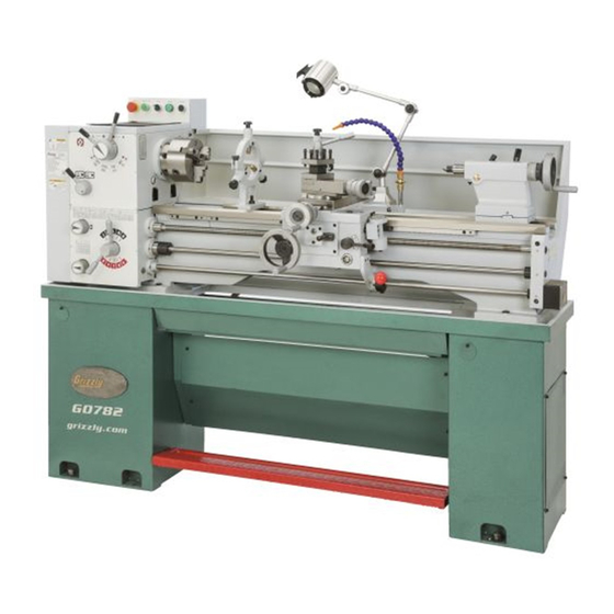
MODEL G0782
13" X 40" GEARHEAD FLOOR LATHE
OWNER'S MANUAL
(For models manufactured since 10/15)
COPYRIGHT © AUGUST, 2015 BY GRIZZLY INDUSTRIAL, INC. REVISED MAY, 2018 (HE)
WARNING: NO PORTION OF THIS MANUAL MAY BE REPRODUCED IN ANY SHAPE
OR FORM WITHOUT THE WRITTEN APPROVAL OF GRIZZLY INDUSTRIAL, INC.
#WK17494 PRINTED IN CHINA
V2.05.18
Advertisement
Table of Contents

Related Manuals for Grizzly G0782


Summary of Contents for Grizzly G0782
- Page 1 OWNER'S MANUAL (For models manufactured since 10/15) COPYRIGHT © AUGUST, 2015 BY GRIZZLY INDUSTRIAL, INC. REVISED MAY, 2018 (HE) WARNING: NO PORTION OF THIS MANUAL MAY BE REPRODUCED IN ANY SHAPE OR FORM WITHOUT THE WRITTEN APPROVAL OF GRIZZLY INDUSTRIAL, INC.
- Page 2 This manual provides critical safety instructions on the proper setup, operation, maintenance, and service of this machine/tool. Save this document, refer to it often, and use it to instruct other operators. Failure to read, understand and follow the instructions in this manual may result in fire or serious personal injury—including amputation, electrocution, or death.
-
Page 3: Table Of Contents
Table of Contents INTRODUCTION ..........2 Manual Feed ..........44 Contact Info............ 2 Spindle Speed..........45 Manual Accuracy ........... 2 Power Feed..........46 Identification ........... 3 End Gears ............ 49 Controls & Components ......... 4 Threading ............. 52 Machine Data Sheet ........7 Coolant System.......... -
Page 4: Introduction
ID label (see below). This information is required for us to provide proper tech support, and it helps us determine if updated documenta- tion is available for your machine. Manufacture Date Serial Number Model G0782 (Mfd. Since 10/15) -
Page 5: Identification
U. Quick-Change Gearbox Controls (see Page 4 Tool Post for details) K. Compound Rest V. Cross Slide Tailstock (see Page 5 for details) W. Feed Direction Lever To reduce your risk of serious injury, read this entire manual BEFORE using machine. Model G0782 (Mfd. Since 10/15) -
Page 6: Controls & Components
K. Feed Direction Lever: Controls direction of leadscrew and feed rod rotation when spindle lever is used. Figure 1. Control panel and headstock controls and components. Model G0782 (Mfd. Since 10/15) - Page 7 S. Carriage Handwheel: Moves carriage along tailstock offset from spindle centerline. the bed. AB. Offset Locking Set Screw: Locks tailstock Cross Slide Handwheel: Moves cross slide in position left or right of spindle centerline. toward and away from workpiece. Model G0782 (Mfd. Since 10/15)
- Page 8 After the foot brake is used, the spindle lever must be returned to the OFF (middle) position to reset the spindle switches before re-starting spindle rotation. Spindle Lever Gears Figure 5. End gear components. Foot Brake Figure 6. Foot brake and spindle lever. Model G0782 (Mfd. Since 10/15)
-
Page 9: Machine Data Sheet
MACHINE DATA SHEET Customer Service #: (570) 546-9663 · To Order Call: (800) 523-4777 · Fax #: (800) 438-5901 MODEL G0782 13" X 40" GEARHEAD FLOOR LATHE Product Dimensions: Weight................................1320 lbs. Width (side-to-side) x Depth (front-to-back) x Height............... 71-1/2 x 30 x 53-1/2 in. - Page 10 Stand..............................Cast Iron Paint Type/Finish............................Epoxy Fluid Capacities Headstock Capacity..........................4.2 qt. Headstock Fluid Type..............ISO 32 (eg. Grizzly T23963, Mobil DTE Light) Gearbox Capacity............................. 2.1 qt. Gearbox Fluid Type..............ISO 68 (eg. Grizzly T23962, Mobil Vactra 2) Apron Capacity............................1 qt.
-
Page 11: Section 1: Safety
Everyday ery. Never operate under the influence of drugs or eyeglasses are NOT approved safety glasses. alcohol, when tired, or when distracted. Model G0782 (Mfd. Since 10/15) - Page 12 EXPERIENCING DIFFICULTIES. If at any time debris. Make sure they are properly installed, you experience difficulties performing the intend- undamaged, and working correctly BEFORE ed operation, stop using the machine! Contact our operating machine. Technical Support at (570) 546-9663. -10- Model G0782 (Mfd. Since 10/15)
-
Page 13: Additional Safety For Metal Lathes
CLEARING CHIPS. Metal chips can be razor sharp. Avoid clearing them by hand or with a rag. MEASURING WORKPIECE. To reduce risk of Use a brush or vacuum instead. entanglement, never measure rotating workpieces. -11- Model G0782 (Mfd. Since 10/15) -
Page 14: Additional Chuck Safety
Always disconnect the lathe from power additional training from an experienced chuck user before performing these procedures. before using a chuck. -12- Model G0782 (Mfd. Since 10/15) -
Page 15: Glossary Of Terms
The following is a list of common definitions, terms and phrases used throughout this manual as they relate to this lathe and metalworking in general. Become familiar with these terms for assembling, adjusting or operating this machine. Your safety is VERY important to us at Grizzly! Gib: A tapered wedge located along a sliding... -
Page 16: Section 2: Power Supply
To reduce the risk of these hazards, avoid over- loading the machine during operation and make sure it is connected to a power supply circuit that meets the specified circuit requirements. -14- Model G0782 (Mfd. Since 10/15) - Page 17 Minimum Gauge Size ......14 AWG service personnel, and it must comply with Maximum Length (Shorter is Better)..50 ft. all local codes and ordinances. -15- Model G0782 (Mfd. Since 10/15)
-
Page 18: Section 3: Setup
IMPORTANT: Save all packaging materials until you are completely satisfied with the machine and have resolved any issues between Grizzly or the shipping agent. You MUST have the original pack- aging to file a freight claim. It is also extremely helpful if you need to return your machine later. -
Page 19: Inventory
If you cannot find an item on this list, care- fully check around/inside the machine and packaging materials. Often, these items get lost in packaging materials while unpack- ing or they are pre-installed at the factory. -17- Model G0782 (Mfd. Since 10/15) -
Page 20: Cleanup
Figure 11. T23692 Orange Power Degreaser. Repeat Steps 2–3 as necessary until clean, then coat all unpainted surfaces with a quality metal protectant to prevent rust. -18- Model G0782 (Mfd. Since 10/15) -
Page 21: Site Considerations
Wall Min. 30" for Maintenance " Lathe Keep 30" Workpiece Loading Area Unobstructed = Electrical Connection Illustration Not To Scale Figure 12. Minimum working clearances. -19- Model G0782 (Mfd. Since 10/15) -
Page 22: Lifting & Placing
(see Page 5 for reference). 10. Lower lathe into position. Remove back splash so it does not get dam- 11. Re-install back splash. aged when lathe is raised. -20- Model G0782 (Mfd. Since 10/15) -
Page 23: Anchoring To Floor
Grizzly. Lag Screw Flat Washer Machine Base Lag Shield Anchor Concrete Drilled Hole Figure 15. Model H2683 Precision Level. Figure 14. Popular method for anchoring machinery to a concrete floor. -21- Model G0782 (Mfd. Since 10/15) -
Page 24: Lubricating Lathe
Run and Spindle Break-In procedures. Adding Coolant Add the coolant of your choice now. For detailed instructions on where the coolant tank is located and how to add fluid, refer to Coolant System Service on Page 56. -22- Model G0782 (Mfd. Since 10/15) - Page 25 Requirements for 220V on Page 14. Ground Wire Connected L1 N1 0 1 15 2 3 4 8 5 6 L1 L2 Ground Hot Wires Incoming Connected Power Cord Figure 17. Incoming ground and hot wires connected. -23- Model G0782 (Mfd. Since 10/15)
-
Page 26: Test Run
Clear away all tools and objects used during assembly, lubrication, and preparation. Figure 19. Spindle speed set to 70 RPM. -24- Model G0782 (Mfd. Since 10/15) - Page 27 — Investigate and correct strange or unusual noises or vibrations before operating the machine further. Always disconnect the machine from power when investigating correcting potential problems. problem is not readily apparent, refer to Troubleshooting on Page 71. -25- Model G0782 (Mfd. Since 10/15)
-
Page 28: Spindle Break-In
Cross slide and compound slide backlash adjustment (see Page 74). Disengage half nut lever and feed selection Gib adjustments (see Page 75). • lever. Run spindle at 70 RPM for 10 minutes in each direction (first forward, then reverse). -26- Model G0782 (Mfd. Since 10/15) -
Page 29: Section 4: Operations
Read books/magazines or get formal training before beginning any proj- ects. Regardless of the content in this sec- tion, Grizzly Industrial will not be held liable for accidents caused by lack of training. -27- Model G0782 (Mfd. Since 10/15) -
Page 30: Chuck & Faceplate Mounting
These cap screws prevent studs from rotat- ing so they properly engage with camlock during installation. Note: It is normal for studs to have a small amount of play or looseness after installing and tightening the cap screws. -28- Model G0782 (Mfd. Since 10/15) -
Page 31: Chuck Safety & Support Devices
LARGE, VERY HEAVY CHUCKS Fabricated Steel Pre-Threaded Hole Lifting Hook for Lifting Eye Figure 23. Inserting camlock studs into spindle cam holes. Figure 22. Typical lifting, support, and protective devices used when installing/removing chucks. -29- Model G0782 (Mfd. Since 10/15) - Page 32 Spindle & Chuck Camlock Registration Marks Spindle INCORRECT INCORRECT Stud Too High: Stud Too Low: Turn In Turn Out One-Turn One-Turn Figure 26. Registration mark locations. Figure 25. Correcting an improperly installed stud. -30- Model G0782 (Mfd. Since 10/15)
-
Page 33: Chuck Removal
60° and tap it Cylinder again. Make sure all marks on cams and spindle are properly aligned for removal. Poor Scroll CORRECT Gear Engagement INCORRECT Figure 28. Jaw selection and workpiece holding. -31- Model G0782 (Mfd. Since 10/15) -
Page 34: Chuck Jaw Reversal
Rotate Top With help from another person or a holding Jaw 180º device, position workpiece so it is centered in chuck. Figure 29. Reversing the chuck jaws. -32- Model G0782 (Mfd. Since 10/15) -
Page 35: Faceplate
To reduce this risk, use a minimum of THREE independent clamping devices to hold workpiece onto faceplate. Figure 31. Example of a non-cylindrical workpiece mounted on a 4-jaw chuck. -33- Model G0782 (Mfd. Since 10/15) -
Page 36: Tailstock
Non-Cylindrical Workpiece Quill Lock Tailstock Lock Lever Lever Clamp Quill Handwheel Faceplate Figure 32. Example of a workpiece clamped in a faceplate. Figure 33. Example of tailstock and quill lock levers in locked position. -34- Model G0782 (Mfd. Since 10/15) - Page 37 Figure 34. Types of tapered arbors and tooling. Start spindle rotation, unlock quill lock lever, then turn quill handwheel clockwise to feed tool into workpiece. -35- Model G0782 (Mfd. Since 10/15)
- Page 38 Center drill both ends of a piece of round stock, then set it aside for use in Step 5. Use another piece of round stock to make a dead center. Turn it to a 60° point, as illus- trated below. -36- Model G0782 (Mfd. Since 10/15)
- Page 39 Repeat Steps 6–8 until desired accuracy is achieved. Mount test or dial indicator so that plunger is on tailstock quill. Note: If necessary in the following step, refer to the Offsetting Tailstock subsection for detailed instructions. -37- Model G0782 (Mfd. Since 10/15)
-
Page 40: Centers
Figure 43. Example of using a dead center with wear and maximize smooth operation. Using low a faceplate and lathe dog. spindle speeds will also reduce the heat and wear from friction. -38- Model G0782 (Mfd. Since 10/15) - Page 41 To mount a center in tailstock: DISCONNECT MACHINE FROM POWER! Thoroughly clean and dry tapered mating surfaces of tailstock quill bore and center, making sure no lint or oil remains on tapers. -39- Model G0782 (Mfd. Since 10/15)
-
Page 42: Steady Rest
Loosen three locking set screws so finger or it may become difficult to remove later. Also, positions can be adjusted (see Figure 46). over-tightening will result in excessive friction and heat, which may damage the workpiece or center. -40- Model G0782 (Mfd. Since 10/15) -
Page 43: Follow Rest
Tighten locking set screws to secure settings. Figure 48. Follow rest attachment. Note: To reduce the effects of friction, lubri- cate the fingers with anti-seize lubricant, such as Grizzly Model T23962 ISO Moly-D Way Oil (see Accessories on Page 57 for more information) during operation. -41-... -
Page 44: Carriage & Slide Locks
This will allow you to quickly Figure 50. Location of compound rest lock. return the compound rest to that exact angle the next time you need to cut threads. -42- Model G0782 (Mfd. Since 10/15) -
Page 45: Four-Way Tool Post
(e.g., 2.5 x 0.5" = 1.25"). Firmly secure cutting tool with at least two tool post bolts. Check and adjust cutting tool to spindle cen- terline, as instructed in next subsection. -43- Model G0782 (Mfd. Since 10/15) -
Page 46: Manual Feed
Set the compound rest angle by hand-rotating it and securing it with the two cap screws (see Figure 51 on Page 42). The compound rest has an indirect-read graduated dial, which shows the actual distance the tool moves. -44- Model G0782 (Mfd. Since 10/15) -
Page 47: Spindle Speed
These sources will help you take into Figure 58. Spindle speed chart and applicable account the applicable variables in order to deter- spindle speed and range lever positions. mine the best spindle speed for the operation. -45- Model G0782 (Mfd. Since 10/15) -
Page 48: Power Feed
If the feed selection lever and the half nut are engaged at the same time, machine damage could occur. Even though there is a lock-out device to prevent this, it could break if forced. -46- Model G0782 (Mfd. Since 10/15) - Page 49 C. Feed Rate Chart: Displays the settings of the quick-change gearbox levers and dials for the selected feed rate. Refer to Setting Power Feed Rate subsection, beginning on this page, for detailed instructions. -47- Model G0782 (Mfd. Since 10/15)
- Page 50 "B", and the dial marked C–D must be set to position "D". —"R" indicates the lever marked R-S-T-U-V must be set to the "R". The carriage is now set up for a power feed rate of 0.0105 in./rev. -48- Model G0782 (Mfd. Since 10/15)
-
Page 51: End Gears
Figure 66. Power feed change gears. 1.35 2.25 26²⁄ ³ 4 5.25 5.4 5.5 3½ Figure 68. Metric threading change gears. 0.45 0.75 1.25 53¹⁄ ³ 1.75 2.75 0.25 106²⁄ ³ -49- Model G0782 (Mfd. Since 10/15) 1.35 2.25 0.45 0.75 1.25... - Page 52 53¹⁄ ³ Arm Support Hex Nut 0.25 106²⁄ ³ 10½ 13¹⁄ ³ Figure 70. Diametral threading change gears. Figure 72. Arm support and end gears. 2.25 26²⁄ ³ -50- Model G0782 (Mfd. Since 10/15) 0.75 1.25 53¹⁄ ³ 106²⁄ ³...
- Page 53 Note: Position flat, non-stepped face of gears toward headstock so they will mesh with 127T gear in Steps 9–10. 10. Secure 32T and 48T gears with spacers, hex nut, and cap screw removed in Step 8. -51- Model G0782 (Mfd. Since 10/15)
-
Page 54: Threading
26²⁄ ³ levers must be moved to positions "K" and 21 22 24 36 40 23 26 0.45 0.75 1.25 53¹⁄ ³ "T" (see Figure 76). 42 44 48 0.25 80 46 52 106²⁄ ³ -52- Model G0782 (Mfd. Since 10/15) - Page 55 When threading, we recommend using slow- est speed possible and avoiding deep cuts, so you are able to disengage half nut when required and prevent apron from crashing into other components! -53- Model G0782 (Mfd. Since 10/15)
- Page 56 Note: If you want to cut a thread not found on the chart or you do not want to use the chart, you can cut any thread by starting and stopping on the "1" on the thread dial. -54- Model G0782 (Mfd. Since 10/15)
- Page 57 1 to cut any thread if you do not want to use the chart, or if you forget any of the above rules. Table Thread Dial T.P.I. SCALE 5¼ Figure 85. Thread dial position for any numbered TPI. -55- Model G0782 (Mfd. Since 10/15)
-
Page 58: Coolant System
Sulferized oils often are used for threading. For small projects, spot lubrications can be done with an oil can or brush, or omitted completely. Figure 87. Coolant selection table. -56- Model G0782 (Mfd. Since 10/15) -
Page 59: Section 5: Accessories
Indexable inserts ensure cutting sur- serious personal injury or machine damage. faces stay sharp. To reduce this risk, only install accessories recommended for this machine by Grizzly. NOTICE Refer to our website or latest catalog for additional recommended accessories. - Page 60 Built with precision-sealed bearings, designed for heavy-duty use on hollow workpieces. H5786 H5902 Figure 94. Model T10303 Quick-Change 5-Pc. Tool Post Set. Figure 92. MT#3 bull nose rolling centers. www.grizzly.com 1-800-523-4777 order online at or call -58- Model G0782 (Mfd. Since 10/15)
- Page 61 G7030—Threading Tool Holder G7041—Carbide Inserts for Steel (5 Pk.) G7049—Carbide Inserts for Cast Iron (5 Pk.) Figure 96. G9849 Magnetic base/dial indicator combo. Figure 99. G7030 Threading Tool Holder. www.grizzly.com 1-800-523-4777 order online at or call -59- Model G0782 (Mfd. Since 10/15)
- Page 62 Comes with molded case and durable cast iron and feature square head bolts. micrometer adjustment wrench. Figure 101. H2987-91 lathe dogs. Figure 103. G9788 4-Pc. Measuring Tool Set. www.grizzly.com 1-800-523-4777 order online at or call -60- Model G0782 (Mfd. Since 10/15)
- Page 63 Figure 105. Accessory drill chucks and arbor. tive short cuts, and problem solving insights that normally take years of hands-on shop experience to learn. T24869 T24871 Figure 107. Machine shop reference books. www.grizzly.com 1-800-523-4777 order online at or call -61- Model G0782 (Mfd. Since 10/15)
-
Page 64: Section 6: Maintenance
Ensure carriage lock handle is loose. vulnerable to rust if left unprotected (especially parts that are exposed to water soluble cutting fluid). Use a quality ISO 68 way oil (see Page 57 for offerings from Grizzly) to prevent corrosion. -62- Model G0782 (Mfd. Since 10/15) -
Page 65: Lubrication
We recommend using and operation of the lathe, these lubrication Grizzly T23962 (ISO 68) or T23963 (ISO 32) lubri- tasks may need to be performed more fre- cants (see Accessories on, Page 57) for most of quently than recommended here, depend- the lubrication tasks. - Page 66 Replacing V-Belts on Page 79), then close end gear cover before re-connecting lathe to power. Quick-Change Gearbox Oil Type ..Grizzly T23962 or ISO 68 Equivalent Oil Amount .......... 2.1 Quarts Check/Add Frequency ......... Daily Change ....Every 1000 Operating Hours Figure 109.
- Page 67 Apron Ball Oilers Oil Type ..Grizzly T23962 or ISO 68 Equivalent Oil Type ..Grizzly T23963 or ISO 32 Equivalent Oil Amount ..........1.0 Quart Oil Amount ........1 or 2 Squirts Check/Add Frequency ......... Daily Lubrication Frequency ......... Daily Change ....
- Page 68 Make sure the end gear cover remains closed whenever possible to keep the gears free of dust or debris from the outside environment. -66- Model G0782 (Mfd. Since 10/15)
- Page 69 Bedways Lubricating DISCONNECT MACHINE FROM POWER! Oil Type ..Grizzly T23962 or ISO 68 Equivalent Oil Amount ......... As Needed Open end gear cover and remove all end Lubrication Frequency ......... Daily gears shown in Figure 116. Before lubricating the bedways (see Figure 117), Clean end gears thoroughly with mineral spir- clean them with mineral spirits.
-
Page 70: Coolant System Service
BIOLOGICAL & POISON Chip Drawer HAZARD! w/Drain Chute Use correct personal protection equipment when handling coolant. Pump & Tank Follow federal, state, (Inside Cabinet) and fluid manufacturer Figure 119. Additional coolant components. requirements for proper disposal. -68- Model G0782 (Mfd. Since 10/15) - Page 71 Safety Wear ....See Hazards on Page 68 New Coolant ........10.0 Quarts Empty 2-Gallon Buckets w/Lids ......2 Hex Wrench 5mm ..........1 Disposable Shop Rags ...... As Needed Magnets (Optional) ..... As Many As Desired -69- Model G0782 (Mfd. Since 10/15)
-
Page 72: Machine Storage
Loosen or remove V-belts so they do not become stretched during storage period. Note: Be sure to place a maintenance note near power button as a reminder that belts have been loosened or removed. -70- Model G0782 (Mfd. Since 10/15) -
Page 73: Section 7: Service
5. Re-align/replace pulley/shaft, pulley set screw, and key. 6. Motor mount loose/broken. 6. Tighten/replace. 7. Machine incorrectly installed. 7. Tighten mounting bolts; relocate/shim machine. 8. Motor bearings at fault. 8. Test by rotating shaft; rotational grinding/loose shaft requires bearing replacement. -71- Model G0782 (Mfd. Since 10/15) - Page 74 5. Adjust gibs (Page 75). 6. Cutting tool is dull. 6. Replace or resharpen cutting tool. 7. Spindle speed or feed rate is incorrect. 7. Use recommended spindle speed (Page 45) and feed rate (Page 47). -72- Model G0782 (Mfd. Since 10/15)
- Page 75 6. Ways are dry and in need of lubrication. 7. Loosen gib screw(s) slightly (Page 75). 7. Gibs are too tight. 8. Gears broken. 8. Replace gears. 9. Increase clutch spring pressure (Page 78). 9. Feed clutch is slipping. -73- Model G0782 (Mfd. Since 10/15)
-
Page 76: Adjusting Backlash
Test after each adjustment by rotating cross slide leadscrew cover. handwheel back-and-forth until backlash amount is acceptable. Feed leadscrew nut back under cross slide and replace cap screw removed in Step 3. Re-install leadscrew cover and back splash. -74- Model G0782 (Mfd. Since 10/15) -
Page 77: Adjusting Gib
-turn, and tighten front gib screw ⁄ -turn. —To decrease slide tension, loosen front gib screw ⁄ -turn, and tighten rear gib screw ⁄ -turn. Repeat adjustments as necessary until gib screw drag is acceptable. Re-install back splash. -75- Model G0782 (Mfd. Since 10/15) - Page 78 Carriage Lock —To loosen the gib, loosen the set screws. Repeat adjustments as necessary until car- riage adjustment is acceptable. Hold set screws in place and tighten hex nuts. Figure 126. Location of carriage lock. -76- Model G0782 (Mfd. Since 10/15)
-
Page 79: Adjusting Half Nut
Repeat Steps 3–5, if necessary, until you are satisfied with half nut adjustment, then re-install thread dial. -77- Model G0782 (Mfd. Since 10/15) -
Page 80: Adjusting Tailstock Lock
Figure 131. Tailstock lock adjustment components. Tighten hex bolt ⁄ -turn and re-install tailstock. Figure 130. Feed clutch details. Apply tailstock lock lever and verify tailstock is locked and lever is where desired. Re-adjust as necessary. -78- Model G0782 (Mfd. Since 10/15) -
Page 81: Tensioning/Replacing V-Belts
Install new V-belts as a matched set so they Push down on motor and re-tighten motor equally share the load. mount bolts. Tension belts (refer to Tensioning V-Belts on this page). Re-install and secure end gear cover. -79- Model G0782 (Mfd. Since 10/15) -
Page 82: Adjusting Spindle Bearing Preload
Outboard replaced, as this damage will generate End of vibration at higher spindle speeds. Spindle Figure 134. End gear cover removed to access outboard end of spindle. -80- Model G0782 (Mfd. Since 10/15) - Page 83 Do not overtighten outer spanner nut because additional preload can force bearings even tighter against races in headstock and cause headstock to compress or crack, or bearing may quickly fail. 12. Re-install end gear cover. -81- Model G0782 (Mfd. Since 10/15)
-
Page 84: Removing/Installing Gap Insert
Loosen preload cap screw (see Figure 139) a few turns until it no longer contacts head- stock. Preload Cap Screw Dowel Pins w/Jack Nuts Screws (2 of 4) Figure 139. Gap insert retaining fasteners. -82- Model G0782 (Mfd. Since 10/15) -
Page 85: Checking/Replacing Brake Shoes
Tighten preload cap screw until it contacts headstock and resistance can be felt, then tighten it an additional ⁄ -turn. -83- Model G0782 (Mfd. Since 10/15) - Page 86 Figure 140. 11. Start lathe and test brake operation. Step off brake pedal and remove pulley. Figure 141 shows pulley removed and brake shoes exposed. Brake E-Clip Linings Springs Figure 141. Brake assembly. -84- Model G0782 (Mfd. Since 10/15)
-
Page 87: Section 8: Wiring
Technical Support at (570) 546-9663. The photos and diagrams included in this section are best viewed in color. You can view these pages in color at www.grizzly.com. -85- Model G0782 (Mfd. Since 10/15) -
Page 88: Electrical Overview
LXW5-A11D 6-15 Plug (As Recommended) Ground Component Location Work Electrical & Lamp Control Panel Lathe Motor Spindle Rotation Limit Switches (Inside) Brake Limit Coolant Pump Switch (Inside) (Inside) READ ELECTRICAL SAFETY -86- Model G0782 (Mfd. Since 10/15) ON PAGE 85! -
Page 89: Electrical & Control Panel Diagram
22NC Ground To Lamp To Lathe Motor To Coolant Pump To Spindle Limit To Brake Limit Page 86 Page 89 Page 89 Switch Page 86 Switch Page 86 READ ELECTRICAL SAFETY -87- Model G0782 (Mfd. Since 10/15) ON PAGE 85! -
Page 90: Main Wiring Photos
Main Wiring Photos Figure 142. Control panel wiring. READ ELECTRICAL SAFETY -88- Model G0782 (Mfd. Since 10/15) ON PAGE 85! -
Page 91: Lathe Motor Wiring Diagram
Control Panel Figure 143. Lathe motor wiring. Page 87 Coolant Pump Wiring Diagram 220V Pump Motor Connection Ground Electrical & Control Panel Page 87 Figure 144. Coolant pump wiring. READ ELECTRICAL SAFETY -89- Model G0782 (Mfd. Since 10/15) ON PAGE 85! -
Page 92: Section 9: Parts
SECTION 9: PARTS We do our best to stock replacement parts when possible, but we cannot guarantee that all parts shown are available for purchase. Call (800) 523-4777 or visit www.grizzly.com/parts to check for availability. 86 87 89-1 89-2 89-3... - Page 93 Bed (Cont.) -91- Model G0782 (Mfd. Since 10/15)
- Page 94 ELECTRICAL BOX MOUNTING PLATE P07820057 FLAT WASHER 6MM P07820097 DIN RAIL P07820058 COTTER PIN 2 X 33MM STANDARD P07820098 PHLP HD SCR M4-.7 X 6 P07820059 CLEVIS PIN 8 X 21 P07820099 V-BELT AX33 -92- Model G0782 (Mfd. Since 10/15)
-
Page 95: Headstock
Headstock 101 102 -93- Model G0782 (Mfd. Since 10/15) - Page 96 Headstock (Cont.) -94- Model G0782 (Mfd. Since 10/15)
- Page 97 Headstock (Cont.) -95- Model G0782 (Mfd. Since 10/15)
- Page 98 TAPERED ROLLER BEARING 30210 P07820147 PULLEY P07820197 GEAR 37T P07820148 COTTER PIN M2 X 40 STANDARD P07820198 GEARED SLEEVE 37T P07820149 CLEVIS PIN 8 X 24 P07820199 KEY 8 X 8 X 18 P07820150 ROCKER -96- Model G0782 (Mfd. Since 10/15)
- Page 99 SPACER P07820214 O-RING 25 X 2.4 P07820234 EXT RETAINING RING 20MM P07820215 SHAFT P07820235 GEAR 37T P07820216 EXT RETAINING RING 42MM P07820236 BRAKE SHOES P07820217 GEAR 30T P07820237 RUBBER MAT P07820219 FLAT WASHER 12MM -97- Model G0782 (Mfd. Since 10/15)
-
Page 100: Gearbox
Gearbox 314 315 -98- Model G0782 (Mfd. Since 10/15) - Page 101 Gearbox (Cont.) 352 353 383 384 386 387 -99- Model G0782 (Mfd. Since 10/15)
- Page 102 P07820352 BUSHING P07820403 ARM SUPPORT P07820353 CAP SCREW M6-1 X 16 P07820404 KEY 5 X 5 X 14 P07820354 BEARING COVER P07820405 BEARING COVER P07820355 BEARING COVER GASKET P07820406 CAP SCREW M6-1 X 14 -100- Model G0782 (Mfd. Since 10/15)
-
Page 103: Apron
Apron 586 587 -101- Model G0782 (Mfd. Since 10/15) - Page 104 P07820549 HALF NUT INDICATOR P07820595 SPACER P07820550 OIL SIGHT GLASS M20-1.5 P07820596 COMBO GEAR 36T/20T P07820551 ROLL PIN 5 X 35 P07820597 SHAFT P07820552 COMPRESSION SPRING P07820598 SET SCREW M5-.8 X 4 CONE-PT P07820553 STEEL BALL 5MM -102- Model G0782 (Mfd. Since 10/15)
-
Page 105: Cross Slide
Cross Slide -103- Model G0782 (Mfd. Since 10/15) -
Page 106: Compound Slide
Compound Slide -104- Model G0782 (Mfd. Since 10/15) - Page 107 635 P07820635 PHLP HD SCR M4-.7 X 12 673 P07820673 SHOULDER SCREW M8-1.25 X 12, 10 X 65 636 P07820636 HEX NUT M6-1 674 P07820674 LEADSCREW NUT 637 P07820637 HEX BOLT M8-1.25 X 25 -105- Model G0782 (Mfd. Since 10/15)
-
Page 108: Tailstock
P07820736 TAILSTOCK BASE P07820717 HANDWHEEL HANDLE 10 X 75 P07820737 CLAMP PLATE P07820718 SHOULDER SCREW M8-1.25 X 12, 10 X 65 P07820738 BALL OILER 8MM PRESS-IN P07820719 INT THREAD CAP SCR M8-1.25 X 20, M5-.8 -106- Model G0782 (Mfd. Since 10/15) -
Page 109: Steady & Follow Rests
P07820811 CAP SCREW M6-1 X 30 P07820821 CAP SCREW M8-1.25 X 45 P07820812 PIVOT STUD M10-1.5 X 20 P07820822 BALL BEARING 625ZZ P07820813 ROLL PIN 5 X 24 P07820823 DOWEL PIN 5 X 16 -107- Model G0782 (Mfd. Since 10/15) -
Page 110: Electrical
924 P07820924 COOLANT PUMP CORD 14G 3W 108" 912 P07820912 GROUNDING BLOCK 6-TERMINAL 925 P07820925 SPINDLE SWITCH CORD 14G 5W 108" 913 P07820913 TERMINAL BAR 6P 926 P07820926 BRAKE LIMIT SWITCH CORD 14G 3W 48" -108- Model G0782 (Mfd. Since 10/15) -
Page 111: Accessories
1031-4 P07821031-4 LATHE CHUCK KEY 10MM 1016 P07821016 HEX WRENCH 6MM 1032 P07821032 GEAR 85T 1017 P07821017 HEX WRENCH 5MM 1033 P07821033 DRILL CHUCK ARBOR MT3 X B16 1018 P07821018 HEX WRENCH 4MM 1034 P07821034 DRILL CHUCK B16 1.5-13MM -109- Model G0782 (Mfd. Since 10/15) -
Page 112: Labels & Cosmetics
FOR GRIZZLY MACHINES ONLY! DO NOT REPRODUCE OR CHANGE THIS ARTWORK HAZARD! oil-resistant material gloves to prevent getting WITHOUT WRITTEN APPROVAL! Grizzly will not accept labels changed without approval. To reduce risk of death IMPACT INJURY Remove chuck key caught in moving parts. - Page 113 Would you recommend Grizzly Industrial to a friend? _____ Yes _____No Would you allow us to use your name as a reference for Grizzly customers in your area? Note: We never use names more than 3 times. _____ Yes _____No 10.
- Page 114 FOLD ALONG DOTTED LINE Place Stamp Here GRIZZLY INDUSTRIAL, INC. P.O. BOX 2069 BELLINGHAM, WA 98227-2069 FOLD ALONG DOTTED LINE Send a Grizzly Catalog to a friend: Name_______________________________ Street_______________________________ City______________State______Zip______ TAPE ALONG EDGES--PLEASE DO NOT STAPLE...
-
Page 115: Warranty And Returns
WARRANTY AND RETURNS Grizzly Industrial, Inc. warrants every product it sells for a period of 1 year to the original purchaser from the date of purchase. This warranty does not apply to defects due directly or indirectly to misuse, abuse, negligence, accidents, repairs or alterations or lack of maintenance.