
Related Manuals for AEG AS-IC01-2 Series


Summary of Contents for AEG AS-IC01-2 Series
- Page 1 THREE-PHASE GRID-TIED SOLAR INVERTER AS-IC01-2 (12 kW TO 30 kW) INSTALLATION INSTRUCTIONS PD201808 AEG GRID-TIED THREE-PHASE SOLAR INVERTER (12-30 kW) V.2-18 EN...
- Page 2 This installation manual is intended for dealers and installers involved in the planning, installation and commissioning of photovoltaic systems deploying AEG solar inverters. These instructions are meant to provide you with valuable infor- mation to ensure that your PV installation runs smoothly and achieves optimal yields over its whole lifecycle.
-
Page 3: Table Of Contents
3.3.1 Installation of three-phase inverters ..........................................21 3.4 Electrical installation ....................................................23 3.4.1 Connection of solar modules ..............................................23 3.4.2 AC connection of three-phase inverters 12 kW to 30 kW ..............................25 4. Operation............................................................26 PD201808 AEG GRID-TIED THREE-PHASE SOLAR INVERTER (12-30 kW) V.2-18 EN... - Page 4 6.2 Optional communication ..................................................47 6.3 AEG WiFi200 (AEG WiFi Stick) communication module ..................................47 6.3.1 AEG WiFi Stick product overview ............................................ 47 6.3.2 Remote Monitoring and Local Monitoring; the AEG InverterControl App and Portal ................48 7. Troubleshooting ........................................................50 8. Contact ..............................................................51 9.
-
Page 5: Safety Precautions
1. Safety Precautions This section describes relevant warning symbols recurring in the installation and operation manual of AEG three-phase solar inverters of the series AS-IC01-2. Icons highlight relevant information for the physical and property safety of the user. Compliance to the provided instructions is essential to prevent physical injury and product damage. -
Page 6: Delivery And Installation
Take measurements to avoid electrostatic discharge during relevant opera- tions. Technical personnel (Operators) who can carry out installation, wiring, commissioning, maintenance, troubleshooting and replacement of the AEG inverter series must meet the following requirements: • The Operator has to be professionally trained •... -
Page 7: Grid-Tied Operation
Ensure that unauthorized third parties do not access the maintenance area during maintenance op- erations. Secure the area by affixing temporary warning signs to dissuade third parties from entering the area. PD201808 AEG GRID-TIED THREE-PHASE SOLAR INVERTER (12-30 kW) V.2-18 EN... -
Page 8: Storage
Do not dispose the inverter with household waste. The inverter and its components should be dealt with as industrial waste. The user has the responsibility and obligation to send the inverter to the locally appointed organization for recycling and disposal. PD201808 AEG GRID-TIED THREE-PHASE SOLAR INVERTER (12-30 kW) V.2-18 EN... -
Page 9: Product Overview
AC energy which has the same frequency and phase as the public grid; this electricity can then be fed to the grid. AEG AS-IC01-2 series of three-phase grid-tied solar inverters are only deployed in solar grid-tied power generation system. The DC input is only provided by crystalline silicon solar modules whose negative and positive poles are not grounded. -
Page 10: Supported Grid Connection Structure
2.1.2 Supported grid connection structure The AEG inverter series AS-IC01-2 supports TN-S, TN-C, TT and IT grid connection. When applied to the TT connection, the N-to-PE voltage should be less than 30V. Figure 2: Grid type PD201808 AEG GRID-TIED THREE-PHASE SOLAR INVERTER (12-30 kW) V.2-18 EN... -
Page 11: Product Appearance
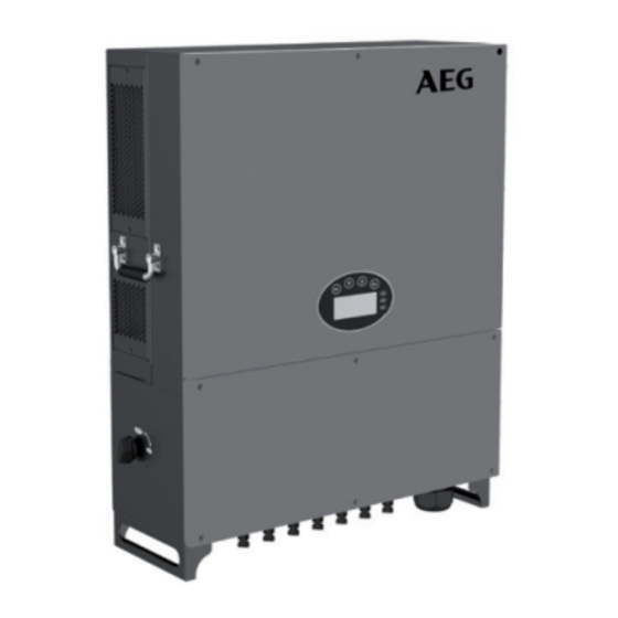
2.2 Product Appearance Figure 3: Scheme of AEG inverter AS-IC01-2 series 12-17 kW (top) and 20-30 kW (bottom); Table 2 (below): Details of the Scheme of AEG inverters AS-IC01-2 (12-17 kW and 20-30 kW) Item Instruction Cover Operational panel LED indicators, LCD screen and buttons... -
Page 12: Labels
Trademark Product type / Model (Product Namecode) Serial Number Product characteristics Certification standards Certification standards / Safety Information Manufacturer Information Figure 4: Example of packaging label PD201808 AEG GRID-TIED THREE-PHASE SOLAR INVERTER (12-30 kW) V.2-18 EN... -
Page 13: Product Label
EU WEEE mark. The product cannot be disposed of as household waste. Safety warning: Hazardous electricity can cause shock, burs or death. For proper use the installation manual should be consulted. PD201808 AEG GRID-TIED THREE-PHASE SOLAR INVERTER (12-30 kW) V.2-18 EN... -
Page 14: Product Models
Three-phase grid-tied solar inverter AS-IC01-30000-2 30000 Table 3: Current inverter models in the AEG AS-IC01-2 series up to 30 kW 2.4 Technical parameters Below is an overview of the technical parameters of the product in series AS-IC01 and AS-IC01-2. Technical specifications are subject to change without previous notice. - Page 15 Input overvoltage protection, input overcurrent protection, DC isolation monitoring, DC monitor- Protection ing, grounding fault current monitoring, grid monitoring, island protection, short circuit protection, overheating protection etc. Table 4: Technical parameters PD201808 AEG GRID-TIED THREE-PHASE SOLAR INVERTER (12-30 kW) V.2-18 EN...
-
Page 16: Dimensions And Weight
AS-IC01-12000-2 / AS-IC01-15000-2/ AS-IC01-17000-2 AS-IC01-20000-2 / AS-IC01-25000-2/ AS-IC01-30000-2 Table 5: Dimensions and weight of the products in the AS-IC01-2 series up to 30 kW 3. Installation The following section describes how to install and connect the inverter to the grid-tied solar system. - Page 17 Following is the detailed packing list of the three-phase inverters (12 to 70 kW and 20 to 30 kW are listed separately): Figure 7A: Packing list of three-phase inverter 12 kW to 17 kW Detailed packing list of three-phase inverters of AS-IC01-2 series 12 kW to 17 kW: Item...
- Page 18 Figure 7B: Packing list of three-phase inverter 20 kW to 30 kW Detailed packing list of three-phase inverters of AS-IC01-2 series 20 kW to 30 kW: Item Quantity Product (AS-IC01-20000-2 / AS-IC01-25000-2 / AS-IC01-30000-2) 1 unit Installation bracket 1 unit...
-
Page 19: Before Installation
Do not remove any inverter part or component, otherwise damage to the device and physical injury may occur. PD201808 AEG GRID-TIED THREE-PHASE SOLAR INVERTER (12-30 kW) V.2-18 EN... - Page 20 Figure 8A: Optimal mounting height (mm) Figure 8B: Installation spacing (mm) Figure 8C: Side-by-side installation spacing requirement (mm) Figure 8D: Correct (and not correct) installation position of the AEG inverter PD201808 AEG GRID-TIED THREE-PHASE SOLAR INVERTER (12-30 kW) V.2-18 EN...
-
Page 21: Connection Cables
3.2.3 Connection cables Compatibly with the AEG inverter´s AC/DC connector specifications for different inverter models, below is an overview of the cable specifications: DC side AC side Min. cross-section Min.cross-section Min.cross-section Model area mm² (length ≤50m) area mm² area mm² (length N/PE (length >50m) -
Page 22: Mechanical Installation
3.3 Mechanical installation As the installation place and materials the inverter is installed on may vary, the AEG inverter can be installed by different mounting methods. It is recommended to install the inverter vertically to firm wall or metal bracket. Taking the typical installation environment as example, the manual describes how to install the inverter on concrete wall. - Page 23 6. Ensure that the inverter is installed properly and tighten the M6 x 16 bolts into the screw holes on the left and right side of the inverter (tightening torque: 4 N•m) as shown below. Figure 11F: Installation of M6 x 16 bolts PD201808 AEG GRID-TIED THREE-PHASE SOLAR INVERTER (12-30 kW) V.2-18 EN...
-
Page 24: Electrical Installation
3.4 Electrical installation This section illustrates the detailed electrical installation and related safety instructions for AEG inverter series AS-IC01 and AS-IC01-2. Public electric grid Net meter Solar modules AEG solar inverter Monitoring equipment Communication converter Figure 12: Block diagram of a grid-tied solar system Improper operation during the wiring process can cause fatal injury to the operator or unrecoverable damage to the inverter. - Page 25 4. Connect the DC connector to the inverter and ensure it is tightly fastened. If you need to remove the connector from the inverter, you can help yourself by inserting a screwdriver into the connector hole. PD201808 AEG GRID-TIED THREE-PHASE SOLAR INVERTER (12-30 kW) V.2-18 EN...
-
Page 26: Ac Connection Of Three-Phase Inverters 12 Kw To 30 Kw
4. Pull out the AC terminal rail as shown below (Figure 14C). Figure 14A: Removing the waterproof cover Figure 14B: Removing the fixing screws of the rail Figure 14C: Pull out the rail PD201808 AEG GRID-TIED THREE-PHASE SOLAR INVERTER (12-30 kW) V.2-18 EN... -
Page 27: Operation
Ensure that the mechanical installation meets the requirement mentioned in section 3.3; Ensure that the electrical installation meets the requirement mentioned in section 3.4; 4. Ensure all the switches are on “off” position; PD201808 AEG GRID-TIED THREE-PHASE SOLAR INVERTER (12-30 kW) V.2-18 EN... -
Page 28: Grid-Tied Operation
5.3 for detailed information, and then stop operation as explained in section 4.3; finally, solve the problems as referred to in chapter 7. If all faults are solved, follow the indications in chapter 4. PD201808 AEG GRID-TIED THREE-PHASE SOLAR INVERTER (12-30 kW) V.2-18 EN... -
Page 29: Stopping
If necessary, Every six months and replacement clean the air inlet and outlet. If the fan is not functioning properly, it needs to be replaced (see section 4.2.2) PD201808 AEG GRID-TIED THREE-PHASE SOLAR INVERTER (12-30 kW) V.2-18 EN... -
Page 30: Maintenance Guide
Remove the inverter (reversing the procedure described in 3.3) 4. Remove the cooling chamber or the fan mounting plate as shown below: Figure 15A: Remove the cooling chamber Figure 15B: Remove the fan mounting plate PD201808 AEG GRID-TIED THREE-PHASE SOLAR INVERTER (12-30 kW) V.2-18 EN... - Page 31 8. Disassemble the damaged inverter fan as shown in Fig. 15C below, then install the new fan back to its original position and connect the fan power and control cable. Figure 15C: Replace the fans PD201808 AEG GRID-TIED THREE-PHASE SOLAR INVERTER (12-30 kW) V.2-18 EN...
-
Page 32: Display Panel
Figure 16A: AS-IC01-2 Operation Panel 5.1 LED indicators There are three LED indicators on the panel: “Run”, operation indicator, green; “Warn” recoverable fault indicator, yellow; “Fault”, unrecoverable fault indicator, red. PD201808 AEG GRID-TIED THREE-PHASE SOLAR INVERTER (12-30 kW) V.2-18 EN... - Page 33 Red indicator is on, others are off : Current-leakage or unqualified output power energy of the in- Warn verter (E007, E010, E014, E017, E018 or E020). De-couple the Fault inverter from the system before maintenance. PD201808 AEG GRID-TIED THREE-PHASE SOLAR INVERTER (12-30 kW) V.2-18 EN...
-
Page 34: Operation Panel
Display Area Display Area Status Area Fault Code Menu Figure 16B: Main interface Figure 16B above shows the main interface of the LCD screen. The LCD screen displays the following items: PD201808 AEG GRID-TIED THREE-PHASE SOLAR INVERTER (12-30 kW) V.2-18 EN... -
Page 35: Functions Operation
Grid current U (IoutU) Leakage current (Ileak) Stop running time of today (Today OFF) Grid current V(IoutV) Temperature 1 (Tinv1) Stop running time of yesterday (Last OFF) Table 15B: monitoring parameters PD201808 AEG GRID-TIED THREE-PHASE SOLAR INVERTER (12-30 kW) V.2-18 EN... -
Page 36: History
L a n g u a g e C a s h / p r i c e S e t M o d e l Figure 21: Settings information PD201808 AEG GRID-TIED THREE-PHASE SOLAR INVERTER (12-30 kW) V.2-18 EN... - Page 37 Soft Ver Fault Setup Model : Independ 1 : A 005 Grid under freq Independ 2 : A 001 Input under Volt Parallel Control Menu On / Off Factory Clear Restart PD201808 AEG GRID-TIED THREE-PHASE SOLAR INVERTER (12-30 kW) V.2-18 EN...
- Page 38 V a l / k W h : 0 0 . 5 0 € / 1 k W h through “ ” or “ ”. Then press “ENT” again to edit the PD201808 AEG GRID-TIED THREE-PHASE SOLAR INVERTER (12-30 kW) V.2-18 EN...
- Page 39 Press “ ” or “ ” to select the setting mode and press “ENT” to save the setting or “ESC” to return. If the situation of section 5.4.8 occurs, it is necessary to switch the DC input to “parallel” mode. PD201808 AEG GRID-TIED THREE-PHASE SOLAR INVERTER (12-30 kW) V.2-18 EN...
- Page 40 Instruction Input password 0000 Accessing the “Set power” interface requires a password. You can request it from your supplier if necessary. The Set power interface of AEG inverters features 3 sub- submenu nr. ③: set power P-Lmt Mode menus as below. AEG three-phase inverters only feature LmtPower P.Factor...
- Page 41 “ ” and “ ” to modify, and press “ENT” to ACOV Volt(phase volt) confirm. 263V ACOV Time 0.20s ACUF Freqency 47.6Hz ACUF Time 0.20s ACOF Freqency 51.4Hz ACOF Time 0.20s PD201808 AEG GRID-TIED THREE-PHASE SOLAR INVERTER (12-30 kW) V.2-18 EN...
- Page 42 ACOF1 and ACOF2 together for ACOF protection. ACOV Volt(phase volt) 252V ACOV Time 01.90s ACUF Frequency 49.49Hz ACUF Time 595s ACOF Frequency 50.2Hz ACOF Time 115s Run Restart Time 060s Island protect:on Table 18: Parameter settings PD201808 AEG GRID-TIED THREE-PHASE SOLAR INVERTER (12-30 kW) V.2-18 EN...
-
Page 43: System Information
F a c t o r y C l e a r R e s t a r t Figure 25: Control interface Refer to the below table for detailed information. PD201808 AEG GRID-TIED THREE-PHASE SOLAR INVERTER (12-30 kW) V.2-18 EN... - Page 44 P r e s s E S C t o c a n c e l . setting. Press “ENT” to confirm the operation or press “ESC” to return. Table 19: Inverter control PD201808 AEG GRID-TIED THREE-PHASE SOLAR INVERTER (12-30 kW) V.2-18 EN...
-
Page 45: Mode Settings
T h a i l a n d A u s t r a l i a H o l l a n d H o l l a n d Other Figure 28: Country list PD201808 AEG GRID-TIED THREE-PHASE SOLAR INVERTER (12-30 kW) V.2-18 EN... - Page 46 Available Countries and related grid standards. Specifications are subject to change and can be updated at any time. Please refer to your local grid authorities for indication. Country Grid standards VDE0126; VDE-AR-N4105 Germany Netherlands VDE0126/EN 50438-NL Belgium C10/C11 Other VDE0126 Table 21: Inverter control PD201808 AEG GRID-TIED THREE-PHASE SOLAR INVERTER (12-30 kW) V.2-18 EN...
-
Page 47: Monitoring Communication
This section describes the communication connection of inverter and the inverter’s monitoring system (computers, mobile devices etc). The standard communication mode of AEG AS-IC01 and AS-IC01-2 series of grid-tied solar invert- ers is RS485. The RS485 port can communicate with computers and mobile devices. -
Page 48: Optional Communication
WiFi is the standard communication mode for AS-IC01-2. The AEG WiFi Stick features one RS485 and one WiFi commu- nication port for the data transmission. The AEG WiFi Stick features a general serial port which meets the network stand- ards and has built-in TCP/IP protocol stack for the transformation between the user serial port and WiFi port. -
Page 49: Remote Monitoring And Local Monitoring; The Aeg Invertercontrol App And Portal
12. Other frequency: 20MHz, 40MHz and automatic Table 23: AEG WiFi Stick features The AEG WiFi Stick is released from factory in AP mode. It can be connected with the 485 communication interface of inverters and can be operated over computer or mobile software. - Page 50 Remote monitoring is the recommended monitoring setting for the AEG WiFi Stick. You can find exhaustive information on how to set up your WiFi Stick for Remote Monitoring in the document “AEG WiFi 200 Remote Monitoring Quick Setup Guide” to be found here: www.aeg-industrialsolar.de...
-
Page 51: Troubleshooting
Huge leakage current of the system or E010 Leek Fail Huge leakage current inverter E011 Relay Fault Relay fault Internal relay fault E012 Fan Fail Fan fault Internal fan fault PD201808 AEG GRID-TIED THREE-PHASE SOLAR INVERTER (12-30 kW) V.2-18 EN... -
Page 52: Contact
MCU software version: • Fault code: • Fault description: 8. Contact Solar Solutions GmbH Schneckenhofstrasse 19 60596 Frankfurt am Main Germany www.aeg-industrialsolar.de Technical Support: Mail: inverter-support@aeg-industrialsolar.de Tel: +31 172 205 011 PD201808 AEG GRID-TIED THREE-PHASE SOLAR INVERTER (12-30 kW) V.2-18 EN... -
Page 53: Annex: Warranty Card
Please mail or email a copy of this warranty registration card to: Address:Solar Solutions GmbH, Schneckenhofstrasse 19, 60596 Frankfurt am Main Website:www.aeg-industrialsolar.de Email:inverter-support@aeg-industrialsolar.de All rights reserved Solar Solutions GmbH. Information is subject to changes without notice. PD201808 AEG GRID-TIED THREE-PHASE SOLAR INVERTER (12-30 kW) V.2-18 EN... - Page 54 Solar Solutions GmbH Schneckenhofstrasse 19 60596 Frankfurt am Main, Germany www.aeg-industrialsolar.de...