
Related Manuals for AEG PRotEct PV 4600


Summary of Contents for AEG PRotEct PV 4600
- Page 1 OPERATING INSTRUCTIONS PRotEct PV 4600 on-gRid solaR inVERtER Version 17.03.2011 / Rev 04...
-
Page 2: Table Of Contents
5.3 Connecting the AC-Output Cable 5.4 Connecting the PV-Panel 5.5 Connecting to the connection unit 5.6 Installation checklist 6. Operation of the Protect PV 4600 6.1 Auto-power 6.2 Operating Modes 6.3 Using the LCD Display 6.4 Maximum Power Point Tracking (MPPT) 6.5 LCD Display Messages... -
Page 3: Read This User Manual Before You Start
To obtain the latest manual and product information, please con- tact the inverter’s manufacturer. Thank you for choosing our product. Please keep this manual on hand for quick reference. Start enjoying Protect PV 4600 and your life! -
Page 4: Safety Instructions
1. safety instRUCtions 1. Risk of ElEctRic shock: Alternating Current (AC) and Direct Current (DC) sources are termi- nated in this device. To prevent risk of electric shock during mainte- nance or installation please ensure that all AC and DC terminals are disconnected. -
Page 5: Limited Warranty
Work in compliance with the terms of this Agreement. AEG PS warrants that the Equipment shall be free from defects in de- sign, materials and workmanship for a period of sixty (60) months from... - Page 6 RMA document. Exclusions AEG PS shall not be liable under the Warranty if its testing and exa- mination discloses that the alleged defect in the Equipment does not exist or was caused by your or any third person’s misuse, negligence,...
- Page 7 Warranties. The warranties extend only to pur- chasers and are not extended to any third parties. In no event shall AEG PS, its officers, directors, affiliates or employees be liable for any form of indirect, special, consequential or punitive...
-
Page 8: Overview
3. oveRvieW 3.1 intRoducing thE gRid-connEctEd PV systEm The grid-connected PV System is mainly composed of 4 parts: the PV-panels, the PV-Inverter, the AC-Connection Unit (the connection Interface) and a connection to the Public Grid. When a PV-panel is exposed to sunlight and connected to an inverter, it generates DC power. -
Page 9: Introducing The Grid Pv System
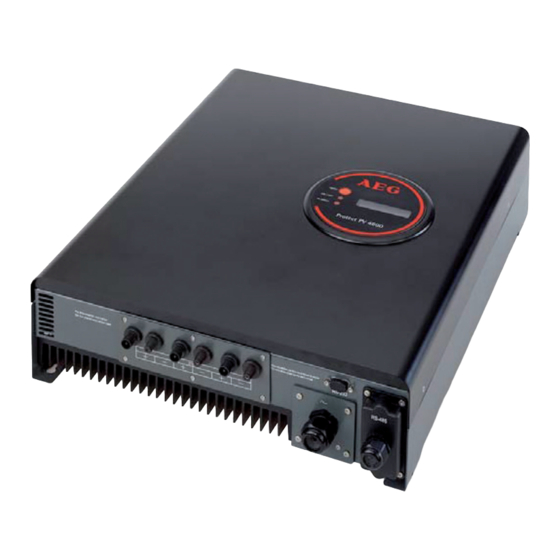
(5) Optional Commu- (4) AC Output nication Port with Cover PRoteCt Pv 4600 inveRteR (1) Connection Panel: The connection panel contains DC and AC termi- nals, and communication ports as detailed below. (2) Heat-sink: Part to dissipate heat produced by the inverter (3) 3 pairs of DC-input terminals: Each input pair consists of positive and negative terminals. -
Page 10: Front Panel Leds
3.3 fRont PanEl lEds There are 2 LED’s on Protect PV 4600, one is green and the other is red. Normally, only the green LED is on during operation. The indicated status are explained as follows: Power on (green LED): The LED lights, if Protect PV is running. The LED lights not, if no power is provided to Protect PV inverter. -
Page 11: Features
4. featURes • Very high conversion efficiency (> 96%) • 3 MPP tracker (Maximum Power Point), independent or parallel operation • IP65 compliant for outdoor application • Embedded LCD, displaying status and system information • Fanless design, quiet operation • Stylish design •... -
Page 12: Installation
5. installation 5.1 insidE PRotEct PV 4600 PackagE The following items are included in your Protect PV 4600 Package: (1) Protect PV 4600 PV-Inverter (2) Installation and Operation Manual (3) 4 Mounting Screws and 4 Blade receptacle (4) 2 Safety-lock screws... -
Page 13: Mounting Protect Pv To The Wall
mounting PRotEct PV to thE wall 1. Choose a dry place, out of direct sunlight with ambient temperature between 0 and 40 °C. 2. Select a wall or solid, vertical surface which is strong enough to sup- port the inverter. 3. - Page 14 4. Mark the positions of the 4 outer mounting holes onto the wall with the bracket as illustrated: Using the oUteR MoUnting holes Upper Mounting Holes Lower Mounting Holes Mounting Bracket...
- Page 15 5. To install the device to a narrow surface, mark the 4 central holes at the back of the bracket. Using the CentRal MoUnting holes Upper Central Mounting Holes Lower Central Mounting Holes 6. Drill the 4 marked holes in the wall, and then drive in the 4 Snap 6.
- Page 16 7. Mount the PV-Inverter onto the bracket as illustrated: Safety Lock Screw 8. Insert the Safety Lock screws to fix the PV-Inverter in place. 9. Install the device vertically to ensure the device is properly fixed to the bracket. LCD Display...
-
Page 17: Connecting The Ac-Output Cable
5.3 connEcting thE ac-outPut cablE Connect your PV-Inverter to the AC-Connection unit via the AC-output cable as following steps: AC-Output Connector AC-Output Cable (≥ 2.0 mm²) AC connection unit (consisting of breaker, fuse, terminals etc.) (1) Open the AC-output cover with a screw driver. - Page 18 (3) Unscrew the cable lock and prepare your AC cable. AC cable lock (4) Remove the rubber plug from inside the AC connector socket. Rubber Plug (no hole in it) (5) Insert the provided rubber bushing with three holes into the AC connector socket.
- Page 19 (6) Now insert the three wires of the AC cable into the bushing holes. (7) Fix the brown wire to L (Line); the blue wire to N (Neutral); and the yellow-green wire to G (Ground). All three wires should be firmly connec- ted.
-
Page 20: Connecting The Pv-Panel
(9) Now screw the Connector Locker in tight to fix the bushing and cable. 5.4 connEcting thE PV-PanEl (1) First make sure that the maximum open circuit voltage Voc of each PV string is below 750VDC UNDER ANY CONDITION. (2) Always connect PV-Panel positive (+) terminal to PV-Inverter DC positive (+) terminal, and the PV-Panel negative (-) terminal to PV- Inverter DC negative (-) terminal. -
Page 21: Connecting To The Connection Unit
(4) To fully optimize the PV DC output set-up, use the following confi- guration guidelines: (a) For PV DC output less than 8.5 A, use a single pair of PV-Inverter DC terminals. (b) For PV DC output between 8.5 A and 17 A, use two sets of inver- ter DC terminals. -
Page 22: Installation Checklist
5.6 installation chEcklist (1) High voltages exist when the PV-Panel is exposed to the sun. Expo- sed terminals of the PV-Panel are alive, and can cause electric shock. Avoid making physical contact with live parts of the device. (2) After the PV-Panels are connected to the PV-Inverter, the output voltage is higher than 100 VDC and the AC grid is not connected to the inverter, the LCD displays “Model= XXXXXX”->... - Page 23 The PV-Inverter is feeding power to the grid, and the green LED dis- plays. Before connecting the PV-Panels to DC terminals, make sure the polarity of each connection is correct. An incorrect connection could damage the device permanently. (5) Congratulations, you have successfully installed your PV-Inverter!
-
Page 24: Operation Of The Protect Pv 4600
6. oPeRation of the PRoteCt Pv 4600 LCD Display Function Button Power-on LED Fault LED 6.1 auto-PowER The PV-Inverter starts up automatically once DC-power from the PV- Panel is sufficient. There are 3 modes of operation. 6.2 oPERating modEs 1. normal In this mode, the PV-Inverter automatically detects the system status and selects the best mode of operation. - Page 25 2. fault The PV-Inverter’s intelligent controller continuously monitors the system status. Unexpected conditions such as grid problems or internal failures are displayed on the LCD and the “Fault LED” turns on. Faults are indicated by the red “FAULT” LED. 3. shutdown At the moment of reduced sunlight, the PV-Inverter automatically shuts down.
-
Page 26: Using The Lcd Display
Before connecting PV-Panels to DC terminals, make sure the polarity of each connection is correct. An incorrect connection could permanently damage the device. 6.3 using thE lcd disPlay Use the Function Button to customize the LCD display settings, or view further information about the internal status of your PV-Inverter. - Page 27 Press the Function Button six times displays the current energy output. Pressing the Function Button seven times displays the Model No. of the Inverter. Pressing Function Button nine times displays the firmware version. Pressing the Function Button a tenth time returns to the status display. adjusting the lCd Contrast Rapidly press the Function Button during the ‘Normal’...
- Page 28 After the highest level is reached, the contrast starts to decrease. A few seconds delay and the display automatically returns to its “Normal” display, if the Function Button is not pressed again. Changing the language Press the Function Button repeatedly until “Set Language”...
- Page 29 locking the display To lock the current display (for example frequency), press and hold the Function Button for about a second. The screen displays “Lock” then returns to the previous screen. Pressing the Function Button on the locked display changes to the next screen.
-
Page 30: Maximum Power Point Tracking (Mppt)
6.4 maximum PowER Point tRacking (mPPt) Due to its advanced design, your PV-Inverter can track the maximum power from any PV-Panel under any condition. If the output power display is stable, your PV-Inverter is converting the maximum power available. If the power reading fl uctuates, the device is tracking power changes due to varying levels of sunlight. -
Page 31: Lcd Display Messages
6.5 lcd disPlay mEssagEs oPERating conditions mEssagE in English dEscRiPtion noRmal woRking status PV inverter is totally shutdown, Power off No display <= 90 V Standby STANDBY 90 V < Input voltage <= 100 V Input voltage range 100 ~ 150 V during Initialization &... -
Page 32: Inverter Fault
lcd disPlay mEssagE continuEd inVERtER fault The readings of 2 microprocessors are Consistent failure ERR MICROS not consistent. Possible cause: CPU and/or other circuit do not function well. The internal temperature is higher than Temperature too high OVERTEMPERATURE normal value The relay between inverter and grid is Output relay failure ERR AC RELAY... -
Page 33: Communication Interface
Use Software Protect PV MONITOR to monitor status of multiple inver- ters. Firmware upgrades are also available via this interface. Protect PV 4600 is integrated with a DB9 socket for the RS232 inter- face. Remove the DB9 socket cover before use. -
Page 34: Troubleshooting
8. tRoUbleshooting The PV-Inverter requires little maintenance. When unexpected situation occurs, please refer to the following table. If the table is insufficient, please call your local dealer. The following table lists common fault messages that display, if the fault LED is lit, and their solutions. tRoublEshooting youR PV-inVERtER fault diagnosis and solution... -
Page 35: Fault Diagnosis And Solution
tRoublEshooting youR PV-inVERtER fault diagnosis and solution mEssagE 1. Check open PV voltage, if it is too close to or over 750 VDC. PV Over Voltage 2. If PV voltage is less than 750 VDC and the problem still occurs, please call service. -
Page 36: Specifications
9. sPeCifiCations modEll PRotEct PV 4600 dc inPut Nominal DC voltage 600 VDC Max. PV open voltage 750 VDC MPPT range 125–700 VDC Working Range 100–750 VDC Number of MPP Tracker Max. Input current 8.5 ADC per Tracker ac outPut... -
Page 37: Compliance Of Standards
10. CoMPlianCe of standaRds Emc: DIN EN 50081, part 1 (EMV-interference emission) (EN 55014, EN 60555 part 2, EN 55011 group 1, class B) DIN EN 50082, part 1 (EMV-interference immunity) gRid intERfEREncE: DIN EN 61000-3-2 gRid monitoRing: Independent disconnection device (MSD, Mains monitoring with allocated Switching Devices) according to VDEW;... -
Page 38: Load Graph And Efficiency Graph
3400 W. load gRaPh P (w) = 8.5 x V The typical efficiency chart related to V and P is shown below. note Results may vary due to test equipment tolerances and product differences. tyPical EfficiEncy gRaPh foR PRotEct PV 4600... - Page 40 OPERATING INSTRUCTIONS, 8000022286 EN, 07/12 - V1 Due to our policy of continuous development, the data in this document is subject to change without notice. AEG is a registered trademark used under licence from AB Electrolux. AEG Power Solutions GmbH Emil-Siepmann-Str. 32...