
Related Manuals for AEG Protect PV 2000


Summary of Contents for AEG Protect PV 2000
- Page 1 OPERATING INSTRUCTIONS protect pV 2000 and 2800 on-Grid solar inVerter DOC n° 07/08/1002-2 Rev 04...
-
Page 2: Table Of Contents
CONTENTS Before you start Safety instructions Limited Warranty 1. Overview 2. Features 3. Installation instructions Opening the package Before installation Mounting Protect PV to the wall Connecting to the grid (AC utility) Connect to PV Panel (DC input) Checking 4. System diagram 5. -
Page 3: Before You Start
Be sure to read this manual carefully before using your PV-Inverter. If you encounter any difficulties during installation or operation, please refer to this manual before contacting your local AEG PS dealer or representative. To obtain the latest manual and product information, please contact AEG PS. -
Page 4: Safety Instructions
® your equipment. 5. Remove the unit carefully from its packaging and inspect for external damage. If you find any imperfections, please contact your local AEG PS dealer. 6. Hot surfaces Although designed to meet all safety requirements, some parts and surfaces of Protect PV are still hot during operation. -
Page 5: Limited Warranty
Work in compliance with the terms of this Agreement. AEG PS warrants that the Equipment shall be free from defects in de- sign, materials and workmanship for a period of sixty (60) months from... - Page 6 Repair or replacement of a defective Equipment or part thereof does not extend the original warranty period. The AEG PS reserves the rights to modify if necessary the mechanism of the equipment in order to fulfil this Agreement. warranty claims procedure...
- Page 7 AEG PS shall not be liable under the Warranty if its testing and exa- mination discloses that the alleged defect in the Equipment does not exist or was caused by your or any third person’s misuse, negligence, improper installation or testing, unauthorized attempts to repair or modify, or any other cause beyond the range of the intended use, or by accident, fire, lightning or other hazard.
- Page 8 warranty extension The original factory warranty can be extended by purchasing additional Extended Warranty Program which extends factory warranty by five (5) years from the date the original factory warranty is ending and guaranty repair and/or replacement of defective parts. Travelling time, expenses and board and accommodation costs will be charged to the Purchaser.
-
Page 9: Overview
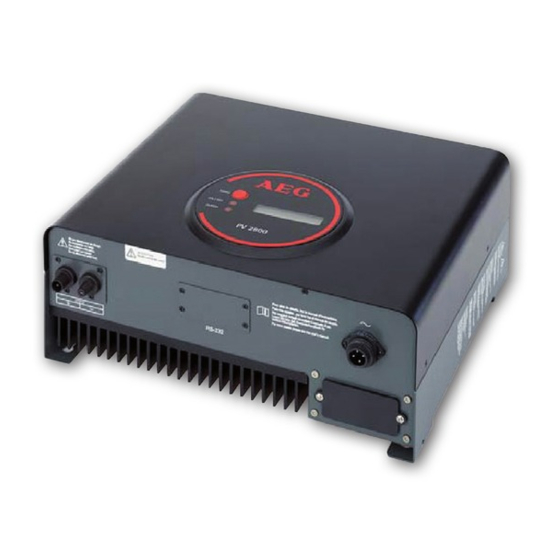
1. OvERviEw Protect Pv 2000 & 2800 DISPLAy InFORMATIOn SWITCH LCD DISPLAy: SHOWInG THE InVERTER STATUS OPERATIOn LED, GREEn, nORMAL OPERATIOn LED, RED, FAULT STATUS UTILITy (AC) COnnECTIOn RS232 COVER SOLAR PAnEL RS485 SLOT InPUT... -
Page 10: Features
2. FEaTuRES • Very high conversion efficiency (>96%) • MPPT (Maximum Power Point Tracking) • Higher power capacity than similar products of the same size. • Embedded LCD display showing complete status information • Natural convection cooling. Quiet, fan-less design •... -
Page 11: Installation Instructions
One mounting frame 4 mounting screws 2 safety-lock screws One AC socket assembly for Protect PV 2000 and 2800 Before installation Before starting installation please consider the following items: This unit is designed for indoor usage. Do not expose the unit to wet, or moist conditions. -
Page 12: Mounting Protect Pv To The Wall
mountinG protect pV to the wall 1. Select a wall or solid vertical surface that can support the PV-Inverter. 2. Protect PV requires adequate cooling space. Allow at least 20cm space above and below the inverter. 20 cm space 20 cm space 3. - Page 13 6. Check the installation conditions a) Do not install the PV- Inverter on a slanted surface b) Check the upper straps of PV-Inverter and ensure it fits on to the bracket c) Insert safety-lock screws to the bottom leg to secure the inverter.
-
Page 14: Connecting To The Grid (Ac Utility)
220VAC), 50/60Hz, and single phase. 2. Switch off by breaker or fuse between PV-Inverter and utility. 3. For Protect PV 2000 and 800, connect AC wires as follows: • Disassemble female socket. • Connect AC wires to connection socket as indicated. - Page 15 To prevent risk of electric shock, ensure that PE is properly grounded before operating the PV-Inverter. 4. Suggested wire-cross section or AC wire model diameter Ø area (mm awG no. (mm) Protect PV 2000 1,29 Protect PV 2800 1,63...
-
Page 16: Connect To Pv Panel (Dc Input)
connect to pV panel (dc input) 1. Make sure the maximum open circuit voltage (Voc) of each PV string is less than 450VDC UnDER Any COnDITIOn. We recommend Voc less than 360VDC with ambient temperature of 25C. 2. Use MC 3 (Multi-contact) connectors for PV array terminals. -
Page 17: System Diagram
4. SySTEm diagRam The typical connection diagram for the entire PV system is shown in the following fi gure. 1. Pv-Panel: Provide DC power to Protect PV inverter 2. Protect Pv PV-inverter Converts DC (Direct Current) power from PV panel(s) to AC (Alternating Current) power. Because Protect PV is grid-connected it controls the current amplitude according to the PV Panel power supply. -
Page 18: Operating Your Pv-Inverter
5. OPERaTiNg yOuR Pv-iNvERTER modes of operation There are 3 different modes of operation. 1. Normal mode: In this mode, Protect PV works normally. Whenever the supplied power from PV panel is sufficient (voltage>150VDC), Protect PV converts power to the grid as generated by the PV panel. If the power is insufficient, (voltage<120VDC) Protect PV enters a “waiting”... - Page 19 • Normal operation: When PV string DC voltage is greater than 150V, Protect PV operates in the normal state. In this state, it feeds power to the grid. Protect PV automatically stops when the PV power is not enough. a. Press the “Function” key repeatedly until “Contrast”...
-
Page 20: Maximum Power Point Tracking (Mppt)
maximum power point trackinG (mppt) A good PV inverter must be able to convert the maximum power from any PV panel. Due to its advanced design, Protect PV PV-Inverter can track the maximum power from your PV panel in any condition. When the displayed power on the LCD output does not change dramatically, Protect PV inverter is converting the maximum power from panels. -
Page 21: Inverter Status
6. iNvERTER STaTuS Protect PV is designed to be user-friendly; therefore, the status of the Inverter can be easily understood by reading the information shown on the front panel display. All possible messages are shown in the following table. display information operatinG conditions messaGe description... -
Page 22: Inverter Fault
Feeding current amount in Feeding current Iac=xx.xA xx.x A Input voltage from PV array, PV array voltage Vdc=xxx.xV xxx.x VDC system fault Earth fault of the PV-panels or Isolation failure ERR ISOLATIOn failure of surge voltage protection Leakage current on ground GFCI active ERR GROUnD FAULT conductor is too high... -
Page 23: Led
inVerter information Model display MODEL PV 4600 Inverter model, xkW inverter The top menu of LCD contrast LCD Contrast COnTRAST setting LCD contrast setting SET COnTRAST Setting the contrast of LCD Hold the present display LCD display lock LCD LOCKED message Waiting for RECOnnEC-... -
Page 24: Communications
Protect PV can accept a special card designed for the port only. The RS485 card is used to work with Protect PV logger and in multiple monitoring applications. AEG Power Solutions GmbH plan to release other communication cards in the near future. For informa- tion of card details, please refer to the user manual of each individual card. - Page 25 3. Firmware upgrade: To keep the firmware up to-date, use the RS232 port and supplied program to upgrade firmware. To do this, please contact your local AEG PS service to prevent risk of damage it is recommended that only authorized personnel perform firmware upgrades.
-
Page 26: Trouble Shooting
In most situations, the Protect PV inverter requires very little service. However, if Protect PV is not able to work perfectly, please refer to the following instructions before calling your local AEG PS dealer. • Should any problems arise, the red (Fault) LED on the front panel turns on and the LCD displays the relevant information. - Page 27 1. Check the open PV voltage, see if it is greater than or too close to 450VDC PV over Voltage 2. If PV voltage is less than 450VDC, and the problem still occurs, please call local service 1. Disconnect PV (+) or PV (-) from the input, restart the PV- Consistent Fault Inverter 2.
-
Page 28: Specifications
9. SPECiFiCaTiONS modell protect pV 2000 protect pV 2800 dc input nominal DC voltage 360 VDC 360 VDC max. PV open voltage 500 VDC 500 VDC MPPT range 150–450 VDC 150–450 VDC Working range 100–500 VDC 100–500 VDC number of MPP Tracker 1 max. -
Page 29: Typical Efficiency Charts Vs. Load
typical efficiency charts Vs. load... -
Page 30: Regulation & Certificates
This form will be filled in by a technician who is responsible for the installation of the solar plant and sent to the AEG PS for this to be registered to then deal with the incident. - Page 32 OPERATING INSTRUCTIONS EN, 07/12 - V1 - 8000022287 AEG is a registered trademark used under license from AB Electrolux AEG Power Solutions GmbH Emil-Siepmann-Str. 32 59581 Warstein-Belecke - Germany Tel.: +49 (0) 2902 763-520/-290 - Fax: +49 (0) 2902 763-1201...