Table of Contents
Advertisement
PL201708 EN LIMITED PRODUCT WARRANTY SOLAR INVERTERS - V. 1. 0
SINGLE-PHASE GRID-TIED
SOLAR INVERTER AS-IR01 & AS-IR01-2
INSTALLATION INSTRUCTIONS
PD20106 AEG GRID-TIED SINGLE-PHASE SOLAR INVERTER V. 1 -18 EN
Solar Solutions GmbH | Schneckenhofstrasse 19 | 60596 Frankfurt am Main | Germany | www.aeg-industrialsolar.de
Solar Solutions GmbH | Schneckenhofstrasse 19 | 60596 Frankfurt am Main | Germany | www.aeg-industrialsolar.de
1-5
Advertisement
Table of Contents

Related Manuals for AEG AS-IR01


Summary of Contents for AEG AS-IR01
- Page 1 PD20106 AEG GRID-TIED SINGLE-PHASE SOLAR INVERTER V. 1 -18 EN Solar Solutions GmbH | Schneckenhofstrasse 19 | 60596 Frankfurt am Main | Germany | www.aeg-industrialsolar.de Solar Solutions GmbH | Schneckenhofstrasse 19 | 60596 Frankfurt am Main | Germany | www.aeg-industrialsolar.de...
- Page 2 This installation manual is intended for dealers and installers involved in the planning, installation and commissioning of photovoltaic systems deploying AEG solar inverters. These instructions are meant to provide you with valuable information to ensure that your PV installation runs smoothly and achieves optimal yields over its whole lifecycle.
-
Page 3: Table Of Contents
3.3.1 Installation of single-phase inverters ................................. 19 3.4 Electrical installation ..........................................20 3.4.1 Connection of solar modules ..................................... 21 3.4.2 AC connection of single-phase inverters ..............................22 PD201806 AEG GRID-TIED SINGLE-PHASE SOLAR INVERTER V.1-18 EN... - Page 4 6.3 AEG WiFi200 (AEG WiFi Stick) communication module......................... 41 6.3.1 AEG WiFi Stick product overview ..................................41 6.3.2 Remote Monitoring and Local Monitoring; the AEG InverterControl App and Portal ........42 7. Troubleshooting ............................................... 44 8. Contact ....................................................45 ...
-
Page 5: Safety Precautions
This section describes relevant warning symbols recurring in the installation and operation manual of AEG single-phase solar inverters of the series AS-IR01 and AS-IR01-2.. Icons highlight relevant information for the physical and property safety of the user. Compliance to the provided instructions is essential to prevent physical injury and product damage. - Page 6 The inverter must be grounded before operation. Do not unauthorizedly open the inverter cover. The electrical parts and components inside the inverter are electrostatic. Take measurements to avoid electrostatic discharge during relevant operations. PD201806 AEG GRID-TIED SINGLE-PHASE SOLAR INVERTER V.1-18 EN...
-
Page 7: Delivery And Installation
Only qualified electricians are allowed to operate the inverter under the permission of local energy authorities. Ensure reliable installation and electrical connection before operation. Do not unauthorizedly open the inverter cover during operation. The electrical parts and components inside the inverter are electrostatic. PD201806 AEG GRID-TIED SINGLE-PHASE SOLAR INVERTER V.1-18 EN... -
Page 8: Maintenance And Inspection
The inverter and its components should be dealt with as industrial waste. 2. Product Overview The following section describes product appearance, packaging, accessories, technical parameters and other relevant information concerning the AEG grid-tied single-phase solar inverters of the AS-IR01 and AS-IR01-2 series. PD201806 AEG GRID-TIED SINGLE-PHASE SOLAR INVERTER V.1-18 EN... -
Page 9: Solar Grid-Tied Power Generation Systems
AEG AS-IR01 and AS-IR01-2 series of single-phase grid-tied solar inverters are only deployed in solar grid-tied power generation system. The DC input is only provided by crystalline silicon solar modules whose negative and positive poles are not grounded. -
Page 10: Product Appearance
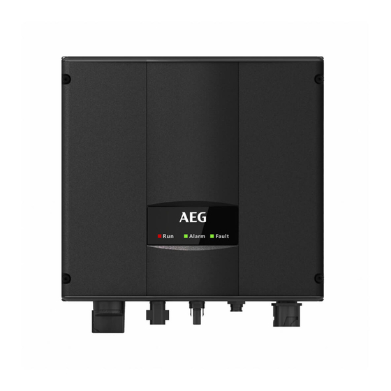
2.2 Product Appearance 2.2.1 Single-phase inverters Figure 3: A- Scheme of AEG inverter AS-IR01 series 750 W to 3000 W; B-Scheme of AEG inverter AS-IR01 4000 W to 5000 W and AS-IR01-2 Item Instruction... -
Page 11: Labels
The product label includes relevant information on the technical properties of the product including model name (Product Number Code), DC Input, AC Output, Protection Level, Grid standards, Certifications, and serial number of the product. PD201806 AEG GRID-TIED SINGLE-PHASE SOLAR INVERTER V.1-18 EN... -
Page 12: Product Models
Manufacturer / Certification / Safety Information Figure 5: Example of packaging label 2.3.3 Product models Here below is an overview of the models currently available for the series AS-IR01 and AS-IR01-2. Technical specifications are subject to change without notice. Product type Model... -
Page 13: Technical Parameters
2.4 Technical parameters Below is an overview of the technical parameters of the product in series AS-IR01 and AS-IR01-2. Technical specifications are subject to change without previous notice. Please refer to the related product datasheet which you can also find under www.aeg-industrialsolar.de... - Page 14 Wall installation mode Input overvoltage protection, input overcurrent protection, DC isolation monitoring, DC monitoring, grounding fault current Protection monitoring, grid monitoring, island protection, short circuit protection, overheating protection Table 4: Technical parameters PD201806 AEG GRID-TIED SINGLE-PHASE SOLAR INVERTER V.1-18 EN...
-
Page 15: Dimensions And Weight
2.5 Dimensions and weight Below is an overview of the dimensions and weight of the products in series AS-IR01 and AS-IR01-2. Technical specifications are subject to change without previous notice. Please refer to the related product datasheet which you can also find under www.aeg-industrialsolar.de... -
Page 16: Unpacking Inspection
Please note that the delivery list of single-phase inverter differs from the one of three-phase inverter. Following is the detailed packing list of single-phase inverters: Figure 7: Packing list of single-phase inverter Detailed packing list of single-phase inverters of AS-IR01 and AS-IR01-2 series: Item Quantity... -
Page 17: Before Installation
AS-IR01-4000 / AS-IR01-4600 / DC connector AS-IR01-5000 / AS-IR01-3000-2 / AS-IR01-4000-2 / AS-IR01-4600-2 / AS- IR01-5000-2: 2 pairs Table 6 Packing list of AS-IR01 and AS-IR01-2 series 3.2 Before installation 3.2.1 Installation tools Detailed list of the tools required for installation: Installation tool... - Page 18 Minimum clearance Lateral 200mm 450mm Bottom 450mm Table 8: Minimum clearance Figure 9: Installation position Do not remove any inverter part or component, otherwise damage to the device and physical injury may occur. PD201806 AEG GRID-TIED SINGLE-PHASE SOLAR INVERTER V.1-18 EN...
-
Page 19: Connection Cables
AS-IR01-3000/ AS-IR01-3000-2 DC500V, C16A, 2P AC240V, C20A, 2P AS-IR01-4000-/AS-IR01-4000-2 DC600V, C16A, 2P AC240V, C25A, 2P AS-IR01-4600 / AS-IR01-5000 / DC600V, C16A, 2P AC240V, C32A, 2P AS-IR01-4600-2 / AS-IR01-5000 -2 Table 10: Breaker specifications PD201806 AEG GRID-TIED SINGLE-PHASE SOLAR INVERTER V.1-18 EN... -
Page 20: Mechanical Installation
3.3.1 Installation of single-phase inverters 3-Ø8 Figure 10: Installation bracket of AS-IR01 750 W to 3000 W inverters 4-Ø8 Figure 11: Installation bracket of AS-IR01 4000 W to 5000 W inverters and AS-IR01-2 inverter series Size of installation brackets: Installation hole Model... -
Page 21: Electrical Installation
Figure 11: Installation bracket of 4000 W to 5000 W inverters 3.4 Electrical installation This section illustrates the detailed electrical installation and related safety instructions for AEG inverter series AS-IR01 and AS-IR01-2. Public... -
Page 22: Connection Of Solar Modules
Then fasten the nut. The wiring of the negative pole is the same as that of the positive pole. Ensure the poles of solar modules are well connected with the connectors; PD201806 AEG GRID-TIED SINGLE-PHASE SOLAR INVERTER V.1-18 EN... -
Page 23: Ac Connection Of Single-Phase Inverters
Fix and connect the DC output cables of the solar module with the matching DC connectors, and then connect the connectors to the inverter’s DC port. Only cables qualified according to the local electrical safety laws and regulations are allowed to be used for connection. PD201806 AEG GRID-TIED SINGLE-PHASE SOLAR INVERTER V.1-18 EN... -
Page 24: Operation
Switch on the integrated DC switch; 4. Switch on the switch on the DC side; Observe the LED indicators and information displayed on the screen. Refer to chapter 5 for detailed infor- mation. PD201806 AEG GRID-TIED SINGLE-PHASE SOLAR INVERTER V.1-18 EN... -
Page 25: Stopping
Check the ambient humidity and dust around inverter, clean Clean the surface Every six months the inverter when necessary. See Section 4.4.2 PD201806 AEG GRID-TIED SINGLE-PHASE SOLAR INVERTER V.1-18 EN... -
Page 26: Maintenance Guide
Restart the inverter. 5. Display panel This section describes the panel display and provides instructions for display operation, including the LED indicators and, if your model features it, the optional LCD display. PD201806 AEG GRID-TIED SINGLE-PHASE SOLAR INVERTER V.1-18 EN... -
Page 27: Led Indicators
Public grid fault (A001, A003, A004, A005or A006); Recoverable fault Yellow indicator is on, others are off: (1) Inverter stand-by. Temperature abnormal(E006); (2) Inverter stand-by. DC input fault (E001); Unrecoverable fault Red indicator blinks every 0.5s, others are off: PD201806 AEG GRID-TIED SINGLE-PHASE SOLAR INVERTER V.1-18 EN... -
Page 28: Operation Panel
Table 15: Inverter states 5.2 Operation panel The following drawings and instructions only apply if you have optionally ordered AS-IR01 and AS-IR01-2 with LCD display. Only in models with optional LCD display, there are 4 buttons on the panel: “ESC”, exit and return ;... -
Page 29: Lcd Display
5.3 LCD display The following drawings and instructions only apply if you have optionally ordered AS-IR01 and AS-IR01-2 with LCD display. LED indicators Opearation Opearation panel panel LCD screen Figure 15: Operation panel All information is displayed on the LCD screen. If there is no button operation in 15 seconds, the LCD screen will dim out to save power. -
Page 30: Functions Operation
2 0 1 2/ 0 1 / 0 5 1 1 : 3 2 : 1 6 A 0 0 5 : G r i d u n d e r f r e q Figure 19: History parameters PD201806 AEG GRID-TIED SINGLE-PHASE SOLAR INVERTER V.1-18 EN... -
Page 31: Statistics
L a n g u a g e C a s h / p r i c e S e t M o d e l Figure 21: Statistic information Parameters can be set in this interface. PD201806 AEG GRID-TIED SINGLE-PHASE SOLAR INVERTER V.1-18 EN... - Page 32 The default password is “0000”; the user can enter the setting interface without password. If the password has already been set, the user can only access the interface by providing the correct password. PD201806 AEG GRID-TIED SINGLE-PHASE SOLAR INVERTER V.1-18 EN...
- Page 33 Time and date need to be set to a later time / date than the one of the system setting. The start time needs to be earlier than the end time. The setting date and time are used for statistics. PD201806 AEG GRID-TIED SINGLE-PHASE SOLAR INVERTER V.1-18 EN...
- Page 34 Accessing the “Personal” interface requires a password. Personal The default password is: 2678..The MPPT starting voltage can be set in this menu from 120V to 160V under the submenu of ”MPPT start volt”. PD201806 AEG GRID-TIED SINGLE-PHASE SOLAR INVERTER V.1-18 EN...
- Page 35 Accessing the “Run Param” interface requires a password. Run Param The default password is: 2678. Set ACUV Volt, ACUV time etc. under the related submenus, press “ ” and “ ” to modify, and press “ENT” to confirm. PD201806 AEG GRID-TIED SINGLE-PHASE SOLAR INVERTER V.1-18 EN...
- Page 36 Generally, it is only necessary to set ACUV and ACUF value for ACUV and ACUF protection. It is necessary to set ACOF1 and ACOF2 together for ACOF protection. Table 18: Parameter settings PD201806 AEG GRID-TIED SINGLE-PHASE SOLAR INVERTER V.1-18 EN...
-
Page 37: System Information
O n / O f f F a c t o r y C l e a r R e s t a r t Figure 25: Control interface Refer to the below table for detailed information. PD201806 AEG GRID-TIED SINGLE-PHASE SOLAR INVERTER V.1-18 EN... - Page 38 “Restore to factory” clears all setting parameters and history Restore to operation records through the panel and restores the factory factory setting. Press “ENT” to confirm the operation or press “ESC” to return. Table 19: Inverter control PD201806 AEG GRID-TIED SINGLE-PHASE SOLAR INVERTER V.1-18 EN...
-
Page 39: Mode Settings
DC input mode via the LCD screen and keypad. 5.5 Functions operation In AS-IR01 or AS-IR01-2 with optional LCD display, after powering up the inverter by DC input for the first time or after restoring factory settings, the LCD screen will show the following message: S O L A R I N V E R T E R I n i t i a l i n g …... - Page 40 Available Countries and related grid standards. Specifications are subject to change and can be updated at any time. Country Grid standards VDE0126; VDE-AR-N4105 Germany Netherlands VDE0126/EN 50438-NL Belgium C10/C11 Other VDE0126 Table 21: Inverter control PD201806 AEG GRID-TIED SINGLE-PHASE SOLAR INVERTER V.1-18 EN...
-
Page 41: Monitoring Communication
This section describes the communication connection of inverter and the inverter’s monitoring system (computers, mobile devices etc). The standard communication mode of AEG AS-IR01 and AS-IR01-2 series of grid-tied solar inverters is RS485. The RS485 port can communicate with computers and mobile devices. -
Page 42: Optional Communication
The WiFi Stick fits the RS485 port of the AEG inverters. WiFi is the standard communication mode for the AEG AS-IC01 and AS-IC01-2. The AEG WiFi Stick features one RS485 and one WiFi communication port for the data transmission. The AEG WiFi Stick features a general serial port which meets the network standards and has built-in TCP/IP protocol stack for the transformation between the user serial port and WiFi port. -
Page 43: Remote Monitoring And Local Monitoring; The Aeg Invertercontrol App And Portal
12. Other frequency: 20MHz, 40MHz and automatic Table 23: AEG WiFi Stick features The AEG WiFi Stick is released from factory in AP mode. It can be connected with the 485 communication interface of inverters and can be operated over computer or mobile software. - Page 44 Remote monitoring is the recommended monitoring setting for the AEG WiFi Stick. You can find exhaustive information on how to set up your WiFi Stick for Remote Monitoring in the document “AEG WiFi 200 Remote Monitoring Quick Setup Guide” to be found here: www.aeg-industrialsolar.de...
-
Page 45: Troubleshooting
Internal communication fault disabled Error of master-slave DSP check bit Huge leakage current of the system or E010 Leek Fail Huge leakage current inverter E011 Relay Fault Relay fault Internal relay fault PD201806 AEG GRID-TIED SINGLE-PHASE SOLAR INVERTER V.1-18 EN... -
Page 46: Contact
2: MCU software version: Fault code: Fault description: 8. Contact Solar Solutions GmbH Schneckenhofstrasse 19 60596 Frankfurt am Main Germany www.aeg-industrialsolar.de Technical Support: Mail: inverter-support@aeg-industrialsolar.de Tel: +31 172 205 011 PD201806 AEG GRID-TIED SINGLE-PHASE SOLAR INVERTER V.1-18 EN... -
Page 47: Annex: Warranty Card
Please mail or email a copy of this warranty registration card to: Address:Solar Solutions GmbH, Schneckenhofstrasse 19, 60596 Frankfurt am main Website:www.aeg-industrialsolar.de Email:inverter-support@aeg-industrialsolar.de All rights reserved Solar Solutions GmbH. Information is subject to changes without notice. PD201806 AEG GRID-TIED SINGLE-PHASE SOLAR INVERTER V.1-18 EN...