Table of Contents
Advertisement
Quick Links
Advertisement
Table of Contents

Related Manuals for GE NX-10


Summary of Contents for GE NX-10
- Page 1 Security NX-10 Alarm System Installers Manual 1060789...
- Page 2 Trademarks and patents GE and the GE monogram are registered trademarks of General Electric. NX-10 product and logo are registered trademarks of GE Security. Other trade names used in this document may be trademarks or registered trademarks of the manufacturers or vendors of the respective products.
-
Page 3: Table Of Contents
Safety terms and symbols.............................. 9 References..................................... 9 Section A Installing and programming a basic system ................10 Chapter A1 Introducing the NX-10 system ....................11 NX-10 diagram ..................................11 NX-10 technical specifications...........................13 NX-10 system..................................14 Parts of the system................................14 Keypads ....................................18 Wireless keypad..............................18 LCD icons ................................21... - Page 4 Selecting a menu option...............................38 Changing a menu option..............................38 Changing selection list entries........................38 Changing binary entries ..........................39 Changing numeric entries ..........................39 Changing phone numbers and phone prefixes...................39 Exiting the menu system ..............................40 Editing text ..................................40 Overview ................................40 Example..................................41 Word library................................41 Guidelines for location-based programming .....................42 Selecting the module to program......................42 Programming a location ..........................42 Exiting the program mode ..........................43...
- Page 5 Programming the outputs ..........................104 Setup for auto-test, auto-arm and opening/closing times ............105 Communicator codes for slow speed formats only................107 Programming partition parameters.......................114 Programming zone configuration groups...................116 NX-10 location-programming worksheets .......................130 Chapter B3 Programming the NX-1048 keypad..................143 Overview....................................143 Configuring the NX-1048 keypad features .......................145 General options..............................145...
- Page 6 Setting the exit buzzer options......................... 153 Glossary..................................... 154 Technical specifications............................. 159 Chapter B4 Programming the other keypads ..................161 Chapter B5 Setting up the RF receivers ....................161 Programming the RF system........................... 162 Defaulting the wireless modules......................163 Programming the wireless detectors....................163 Learning-in additional wireless keypads.....................
- Page 7 NX-10 Installers manual Troubleshooting...............................197 Autotest ................................197 Reporting protocols and formats ..........................197 Reporting fixed codes in SIA and Contact ID ..................197 Special Reports..............................199 SMS SIA reporting message format .......................199 SMS Contact ID reporting..........................201 HomeText control ............................201 Receiving SMS messages from a security system................204 HomeText reporting............................204...
- Page 8 Programming tasks ............................239 Chapter B11 Updating firmware ....................... 242 Overview ................................... 242 Update procedure ................................ 242 Section C References ........................... 244 Appendix 1: Reporting fixed codes in Contact ID or SIA ................245 Appendix 2: Overview of module numbers....................... 248 NX-1701E door swipe modules........................
-
Page 9: Preface
References For more information, refer to the following: NX-10 Menu Structure This menu structure provides a map of the NX-10 menu options, including those for all the additional modules. NX Expander Installation Guide This manual contains detailed information about additional modules and their installation. -
Page 10: Section A Installing And Programming A Basic System
Section A Installing and programming a basic system... -
Page 11: Chapter A1 Introducing The Nx-10 System
NX-10 Installers manual Chapter A1 Introducing the NX-10 system NX-10 diagram Figure 1. NX-10 board diagram Transformer GSM Antenna Connector NetworX Bus (internal) GSM Modem (for status LEDs description, see page 183) NetworX Bus (internal) Audio Tap RF microprocessor Outputs (see Figure 2) - Page 12 Figure 2. NX-10 inputs and outputs Connect to Data terminal of keypad DATA Power (-) and expanders Connect to Positive (+) terminal of POS (+) AUX PWR+ Power (+) keypad and expanders Connect to negative (-) terminal of AUX PWR+...
-
Page 13: Nx-10 Technical Specifications
NX-10 Installers manual NX-10 technical specifications Mains power specifications Mains input voltage, small housing 230 V ~ (+10% / - 15%) / 50 Hz / 25 VA Mains input voltage, large housing 230 V ~ (+10% / - 15%) / 50 Hz / 40 VA Current, typical system, 25 VA transformer 0.12 A ~ / 50 Hz / 25 VA... -
Page 14: Nx-10 System
Ademco/Silent Knight Slow, Silent Knight 4+2 fast, Sescoa/Franklin Fast, SIA, XSIA and custom formats Maximum number of wireless keypads Support for Proximity Reader RF Dual Transceiver Internal, built-in GPRS module Internal, built-in (in NX-10-GSM-EUR and NX-10-GSM-LB-EUR panels only) Parts of the system Table 1. System modules Part number Description Purpose... - Page 15 1 of the 4 locations via the DL900 downloader. 3. A storage device, connected only to the panel. You can read/write from 1 of the 4 locations on the NX-10. NX-590E TCP/IP Module Dual microprocessor-controlled Internet/Intranet interface.
- Page 16 Table 2. Wireless equipment Part Number Part Description Purpose This full wireless indoor siren offers you INDOOR SIREN, 868 MHz TX-7001-05-1 wireless communication and wireless GEN2 operation by batteries with a typical sound output of 108dB. This full wireless outdoor siren offers you OUTDOOR SIREN, 868 TX-7201-05-1 wireless communication and wireless...
- Page 17 NX-10 Installers manual The 4-button keyfob is a portable 4 BUTTON KEYFOB, 868 TX-4131-03-2 wireless device allowing you to arm or MHz GEN2 disarm the system without having to memorise access codes or race to beat entry or exit delays. It offers two...
-
Page 18: Keypads
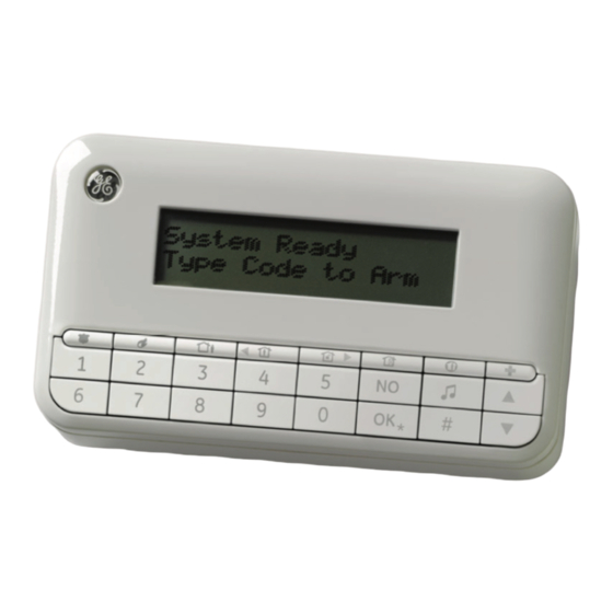
Keypads Wireless keypad The wireless LCD keypad allows you to program the NX-10 system using a menu structure. There is also an option to use the wired keypad with the same functionality. Figure 3. Keypad. The LCD features the white backlight to allow keypad operation in the dark. Illumination level is as low as possible to save energy. - Page 19 NX-10 Installers manual The NX-10 keypad has the following key layout out-of-the-box: Figure 4. Default keypad layout. The four top-row keys with the blank keycaps can be replaced by the installer, as they are supplied with the keypad for this purpose. Figure 3 shows the keypad with the optional function keycaps placed in their default positions (factory setting).
- Page 20 Press to scroll to the start of the LCD message. When in master mode: Disarm Press to disarm the system. Note: The Disarm key works in the master mode only, after the user code and the partition number have been entered. When in the menu: Press to scroll to the end of the LCD message.
-
Page 21: Lcd Icons
NX-10 Installers manual LCD icons The LCD display for the NX-10 keypad consists of two separate sections, one for displaying 2 rows of 16 characters of alphanumeric data, and one for showing icons. The display section on the wireless keypad showing alphanumeric data is only turned ON while the user is operating the keypad, and turns OFF 30 seconds after the last key hit. - Page 22 This icon is only available on the wireless keypad and flashing when the Battery low keypad battery is low. This icon flashes in case of an alarm condition. Alarm This icon is only available on the wireless keypad and indicates RF-link field strength.
-
Page 23: Chapter A2 Installation Guidelines
Keep away from children. To replace the battery, please disconnect it and remove it from the holder. If required, replace with the GE Security BS127N lead batery only. Do not use a different type of batteries. Mounting •... -
Page 24: Defaulting The Panel
CAUTION: Never attempt to solder a mains connection wire’s end where they will be wired to the terminal connectors. The battery used with the NX-10 must be made of materials of flammability class HB or better. The mains switching relay must not be fitted inside the control panel cabinet. -
Page 25: Chapter A3 Installing A Basic System
NX-10 Installers manual Chapter A3 Installing a basic system Installing the NX-10 CAUTION: Before installing the panel: • Ensure that the unit is mounted on a flat, solid, vertical surface so that the base will not flex or warp when the mounting screws/bolts are tightened. -
Page 26: Installing The Keypad
Figure 5. Connecting the battery to the panel. Close the housing. Installing the keypad Mounting the wireless keypad Depending on the configuration, the wireless keypad can be mounted on the wall in a cradle or used as a portable device. To install a wireless keypad: Figure 6. -
Page 27: Mounting The Wired Keypad
Note: Any unauthorized opening of the battery compartment will cause tamper alarm in the system. Mounting the wired keypad There is also an option to use wired keypads with the NX-10 system. To install a wired keypad: Run the NetworX bus cable to the appropriate location on the wall. Insert the cable into the cable opening in the wired keypad's backplate. -
Page 28: Keypad Learning-In Procedure
At the panel side, run the NetworX bus wires through the ferrite (see Figure 9, position ), making one loop, and connect the wires to the standard NetworX bus contacts (see Figure 1, position ). Additionally, connect the shielding to COM (see Figure 9, position Panel Figure 9. -
Page 29: Installing The Wireless Sirens
NX-10 Installers manual not communicate with the panel in this time window, the learning mode is exited. The learning mode can be restarted by switching panel power off and on again. Insert the batteries in the wireless keypad. It starts the keypad initialization process. - Page 30 To install the wireless siren: Select the appropriate location to install the siren, and mount the siren base to the wall. Insert the batteries to power the siren. In case of the indoor siren, the battery holders for four (4) AA 1.5 V batteries and one (1) 9 V battery are located inside the housing of the siren.
- Page 31 NX-10 Installers manual Figure 10. Wireless indoor siren Speaker Tamper 4x AA battery pack Tamper 9 V battery 9 V battery terminal (+) Siren PCB 9 V battery terminal (-) Siren driver (-) 4x AA battery pack (+) Siren driver (+)
- Page 32 TX-7001-05-1 Wireless indoor siren specifications Power supply specifications Electronics Number and type of batteries 4 x AA size, 1.5 V, primary cell Battery capacity 5600 mAh Board operating voltage 2.1 V … 3.1 V Siren part Number and type of batteries 1 x 9V size block, primary cell Battery capacity 600 mAh...
- Page 33 NX-10 Installers manual Figure 11. Wireless outdoor siren Siren PCB Tamper Speaker Tamper Beacon Open collector output 2 (+) for beacon 3X lithium battery pack Open collector output 2 (-) for beacon IO module power cable (black) Open collector output 1 (+) for speaker...
- Page 34 To allow the IO module to control the output on the outdoor siren, you need to cut jumper 3 and then optionally 1 and/or 2. Jumper 3 is a start-up protection. Jumpers 1 and 2 are responsible for timer settings, and you can cut one of them or both, according to the table below.
-
Page 35: Installing The Wireless Sensors
NX-10 Installers manual Installing the wireless sensors Mounting the sensors Select the appropriate location to place the sensor. For recommendations and rules regarding a correct placement of the particular sensor (motion sensor, door/window, smoke, etc.), see the sensor manual enclosed with the device you want to install. -
Page 36: Chapter A4 Programming Guidelines
Country codes The NX-10 has the ability to set different “country codes”. Each country code has specific default settings. When you start your system for the first time (see Powering up the system below) and select keypad defaults during the initial keypad setup, the respective country code is also set up automatically for the panel. -
Page 37: Powering Up The System
Continue using the keypad as normal. Note: When the NX-10 is powered up for the first time, only the single language selected during keypad installation is available. To toggle the user interface language, the available languages must be defined first (Installer... -
Page 38: Navigating The Menus
Changing a menu option The NX-10 has several editors that you can use to change the value of certain programmable menu options. You can change selection list entries, binary entries, phone numbers and text. This section describes how to change selection list entries, binary entries, numeric entries and phone numbers. -
Page 39: Changing Binary Entries
NX-10 Installers manual Press NO to cancel the change and return to the menu option. Changing binary entries Navigate with the keys to the relevant menu option and press OK. The current value for the menu option is displayed, for example, 1 2 3 - - - - 8 means that 1, 2, 3 and 8 are on (included) while 4, 5, 6 and 7 are off (excluded). -
Page 40: Exiting The Menu System
Press OK at this prompt to exit the menu system. Editing text Overview The NX-10 has a text editor that includes a word library. You can use this editor to change the text of certain programmable text options. Navigate with the keys to the relevant menu option and press OK. -
Page 41: Example
NX-10 Installers manual The current text for the menu option is displayed, for example, Zone 2. Do one of the following: • Press to toggle between insert mode and overwrite mode (insert mode allows you to insert new text and overwrite mode allows you to overwrite existing text). -
Page 42: Guidelines For Location-Based Programming
The current state of the word library is displayed. In this case, it is enabled. Use the keys to change the state to disabled and press OK. The keypad beeps once to accept the change and returns to Word Library. Note: In case of wireless keypads, user texts (user names, zone names, etc.) are copied from the keypad to the RF receiver first and then sent to the target keypad (or one-by-one to consecutive keypads). -
Page 43: Exiting The Program Mode
NX-10 Installers manual Exiting the program mode When you have made all the desired changes in programming, it is time to exit the program mode. Press the NO key twice to exit this programming level, and go to the “Enter the device address”... -
Page 44: Chapter A5 Setting Up A Communicator
Chapter A5 Setting up a communicator Reporting The NetworX system supports different modes of reporting events to multiple central stations. There are three phone numbers - each phone number has it own account code, protocol and events. The configured prefix is common to all three phone numbers. If a four-second delay is specified in the prefix, the panel does not look for a dial tone, but performs blind-dialling. -
Page 45: Dual Reporting
NX-10 Installers manual by default and events for phone numbers 2 - 3 are disabled by default. If phone number 1 and phone number 2 are programmed, the default sequence is 1,1 2,2 1,1,2,2 for a total of eight calls to each number. -
Page 46: Split Reporting
Level 1 Level 2 Value State Events Phone Number 1 – Alarms Enabled Phone Number 1 – Alarm Restores Enabled Phone Number 1 – Tampers and Restores Enabled Phone Number 2 – Alarms Enabled Phone Number 2 – Alarm Restores Enabled Phone Number 2 –... -
Page 47: Chapter B1 Selecting The Programming Mode
Selecting the programming mode The NX-10 system allows to use two different programming modes — location-based programming or menu-based programming. In location-based programming you use locations and segments to set appropriate values. In menu-based programming you use a menu tree to enable/disable particular options or to set values. -
Page 48: Chapter B2 Programming The Control Panel
Chapter B2 Programming the control panel Overview You must default the control panel before you begin to program the system. For more information on enrolling and defaulting, see Chapter B7 Enrolling modules. Programming inputs Figure 13. Inputs menu (1) Zone 1 Zone Type Zones 2.1.1.1.1... - Page 49 NX-10 Installers manual A zone may reside in any combination of partitions. A zone that resides in more than one partition becomes a common zone and is reported to its lowest partition number. A common zone is armed only when all the partitions that it belongs to are armed. It is immediately disarmed when one of the partitions it belongs to is disarmed.
-
Page 50: Defining A Zone
is resident, as long as the zone is open. Keyswitch arming will report as User 99 in logs and reports. Entry/Exit 1 Force A trip will start entry delay 1. Absence of a trip during exit delay will enable the automatic bypass Armable or instant mode, if so programmed. -
Page 51: Copying Zone Settings
NX-10 Installers manual Press OK to accept the changes. The keypad beeps once to confirm the change and returns to Zone Name. Scroll to Partitions and press OK. The current partition(s) for that zone are displayed, for example, 1 - - - means that the zone is assigned to partition 1. -
Page 52: Setting Swinger Count
Set the value of Inputs>Swinger Count to 5. For more information see Setting swinger count below. Setting swinger count The swinger shutdown function allows the selected zone to be automatically bypassed after a specified number of alarms. To configure swinger count, you must enable the advanced menu. The following example sets swinger count to 5. -
Page 53: Configuring An Output
NX-10 Installers manual The control panel includes up to 2 programmable on-board auxiliary outputs. To program on-board outputs, select Installer Menu>Control Panel>Outputs. Configuring an output You can change the characteristics of each output. You must specify the events and/or partitions that activate an output and the length of time for which the output is activated. -
Page 54: Configuring The Internal Siren
Data Event Data Event Fire Auxiliary communication failure Fire trouble Radio test Chime Any siren when armed in any mode Expander trouble Alarm memory (pulsating) Dynamic battery test time Zone inactivity If set to follow condition, these events are one second Note: When Event 48 is programmed, it is possible to program a user code's authorization to select which output(s) a particular code activates. -
Page 55: Setting Up The Installer Code
NX-10 Installers manual silent alarm that sends a special report to the central station. To program codes, select Installer Menu>Control Panel>Codes. Note: For EN/INCERT compliance, system access ID needs to be in 6 digit format. Setting up the installer code An installer code may have associated arming options and access rights. -
Page 56: Setting Communication Options
Setting communication options Figure 16. Communication menu Phone Numbers Central Station 2.4.1.1.1 2.4.1.1.1.1 2.4.1 2.4.1.1 2.4.1.1.1.2 Phone Numbers 2 - 6 2.4.1.1.1.3 Same as above 2.4.1.1.1.4 2.4.1.1.1.5 Alarms Events Arm/Disarm/Alarm 2.4.1.1.1.4.1.1 2.4.1.1.1.6 2.4.1.1.1.4.1 Alarm Restores 2.4.1.1.1.4.1.2 Opening/Closing 2.4.1.1.1.4.1.3 Zone Bypass and Restores 2.4.1.1.1.4.1.4 (1) Partition 1 2.4.1.2... -
Page 57: Defining Communication With A Central Station
NX-10 Installers manual Figure 17. Report codes menu Zone Types (1) Day Zone Event Code Report Codes 2.4.4.3.1.1.1 2.4.4.3.1.1 2.4.4.3 2.4.4.3.1 SIA Code 2.4.4.3.1.1.2 Zone Types 2 - 0 CID Code Same as above 2.4.4.3.1.1.3 (1) Partition 1 Partition Reports Restore 2.4.4.3.2... -
Page 58: Defining Communication With Upload/Download Software
press OK. Scroll to Phone numbers>Phone Number 1>Dial Attempts and press OK. Select 3 and press OK. The keypad beeps once to confirm the change and returns to Dial Attempts. Defining communication with a mobile phone You can also treat a telephone (for example, your mobile phone) as a central station. This way you can send voice messages with the NX-535 voice module (if installed) when particular events happen, or you can send a siren tone to your mobile phone in case of an alarm. -
Page 59: Enabling Reporting
NX-10 Installers manual Scroll to Interval>7 days and press OK. The keypad beeps once to confirm the change and returns to Hours/Days?. Scroll to Hour>12 and press OK. The keypad beeps once to confirm the change and returns to Hour. -
Page 60: Configuring Partitions
Configuring partitions Figure 18. Partitions menu Entry Time (1) Partition 1 Timers 2.5.1.1.1 2.5.1 2.5.1.1 Exit Time 2.5.1.1.2 Partitions 2 Entry Time 2.5.1.1.3 Same as above Exit Time 2.5.1.1.4 Quick Arm 2.5.1.2 Feature Select Arming 2.5.1.2.1 2.5.1.2.1.1 Re-exit 2.5.1.2.1.2 Silent Auto Arm 2.5.1.2.1.3 Autom. -
Page 61: Configuring The System
NX-10 Installers manual according to the auto-arm schedule, and enables the personal alarm combination keys so they activate a personal attack alarm when pressed. Ensure the advanced menu is enabled. Navigate with the keys to Control Panel>Partition Settings>Partition 1>Feature Select>Arming and press OK. -
Page 62: Setting Timers
Setting timers You can set timers to control the duration of various system functions. The following example sets the internal siren timer to five minutes. When the siren starts ringing, the timer starts counting down. When the timer is finished, the siren automatically stops. Ensure the advanced menu is enabled. -
Page 63: Setting Arm Schedules
NX-10 Installers manual Setting arm schedules Figure 20. Arm Schedules menu (1) Partition 1 Arm Only After Close Sunday 2.7.1 2.7.1.1 2.7.1.1.1 Monday 2.7.1.1.2 Partitions 2 - Tuesday Same as above 2.7.1.1.3 Wednesday 2.7.1.1.4 Thursday 2.7.1.1.5 Friday 2.7.1.1.6 Saturday 2.7.1.1.7... -
Page 64: Glossary
Navigate with the keys to Schedule Times>Closing/Autoarm>Hour and press OK. Enter 18 and press OK. The keypad beeps once to confirm the change and returns to Hour. Scroll to Minute and press OK. Enter 0 and press OK. The keypad beeps once to confirm the change and returns to Minute. Glossary Location Term... - Page 65 NX-10 Installers manual Location Term Definition 2.1.3.1.1.2 24-hour A zone type where reaction is not dependent on the arm/disarm state of the system. It is permanently active 24 hours a day unless bypassed by forced arming. An example of a 24-hour zone is a fire, panic or glassbreak zone.
- Page 66 Location Term Definition 2.1.3.1.3.4 Swinger Zone A zone characteristic that allows the selected zone to be automatically bypassed after a specified number of alarms. 2.1.3.1.3.5 Bypassable A zone characteristic that allows the zone to be bypassed. 2.1.3.1.3.6 Force Armable A zone characteristic that allows the zone to be force armed.
- Page 67 NX-10 Installers manual Location Term Definition 2.1.3.1.5.3 Dialer Delay A menu option that sets the length of time (in seconds) the dialer waits before reporting an abortable alarm. If the system is disarmed during this time, the abortable alarm is not sent to the central station.
- Page 68 Location Term Definition 2.2.1.1.4 Partitions A menu entry that lists the partitions assigned to the selected output. The selected output can be triggered by an event on these partitions. A zone may reside in any combination of partitions. A zone that resides in more than one partition becomes a common zone and is reported to its lowest partition number.
- Page 69 NX-10 Installers manual Location Term Definition 2.2.2.2.2 Exit Delay Expired A menu option that causes the internal sounder to blast when the exit time expires. 2.2.2.2.3 Closing Kissoff A menu option that causes the internal sounder to blast when the central station receives a closing report.
- Page 70 Location Term Definition 2.3.2.2 Authority A menu entry that groups access options. These options specify the level of access an individual has when using the control panel. 2.3.2.2.1 Arm Only After Closing A menu option that specifies a code that arms the system during the close window only (when the system is scheduled to be armed).
- Page 71 NX-10 Installers manual Location Term Definition 2.4.1 Central Station A menu entry that groups options relating to the central station. This is a remote location that is designed to monitor signals and reports from alarm systems and summon assistance if necessary. This is also known as a control station or ARC.
- Page 72 Location Term Definition 2.4.1.1.1.6.1.3 Opening/Closing A menu option that sends a report to the selected phone number stating when the system is opened (disarmed) and closed (armed). 2.4.1.1.1.6.1.4 Zone Bypass and Restores A menu option that sends a report to the selected phone number when a zone is bypassed.
- Page 73 NX-10 Installers manual Location Term Definition up/download events to the selected phone number. 2.4.1.1.1.7 Partitions to Report A menu option that specifies which partitions are reported to the selected phone number. Important: When you select a partition, ALL events from...
- Page 74 Location Term Definition 2.4.2.6 Call PC on Autotest A menu option that allows the panel to use call back when the central station performs an autotest. After the test report is delivered to the central station, the panel calls the up/download software using the call back phone number.
- Page 75 NX-10 Installers manual Location Term Definition 2.4.4.1 Partition Reports A menu option that specifies the events that are enabled for each partition. Events specified in this option are related to all partitions in the system. 2.4.4.1.1 Opening/Closing A menu option that enables opening/closings reporting.
- Page 76 Location Term Definition 2.4.4.2.1.5 RF Low Battery A menu option that sends a report to the central station when a low battery condition occurs in an RF sensor. 2.4.4.2.1.6 CleanMe A menu option that sends a report to the central station when a smoke detector is dirty.
- Page 77 NX-10 Installers manual Location Term Definition 2.4.4.3.1 Zone Types A menu entry that groups all reporting codes for the selected zone type. 2.4.4.3.1.1.1 Event Code A menu option that sets the event code reported for the selected zone type. 2.4.4.3.1.1.2...
- Page 78 Location Term Definition 2.4.4.3.3.5 Keypad Tamper A menu entry that groups the report codes sent for the keypad tamper event. 2.4.4.3.4 Power A menu entry that groups report codes sent to the central station when power related events occur. 2.4.4.3.4.1 Mains Failure A menu entry that groups the codes used to report a mains failure event.
- Page 79 NX-10 Installers manual Location Term Definition 2.4.4.3.6.6 End Download A menu entry that groups the report codes sent to the central station when downloading is complete. 2.4.5 Custom Format A menu option that allows you to build communication formats if using a non-standard central station. Consult technical support before using this option and the related options.
- Page 80 Location Term Definition 2.5.1.2.1.1 Quick Arm A menu option that enables the function keys for part arming and for full arming. These options work on a single- partition keypad only. If the Quick Arm menu option is enabled, the user can arm the system by simply pressing the Arm Away, Arm Stay or Night Mode button, otherwise it is necessary to enter the user code first.
- Page 81 NX-10 Installers manual Location Term Definition 2.5.1.2.1.10 Keyswitch Arm Stay A menu option that allows to arm the partition in Stay mode with a keyswitch. 2.5.1.2.1.11 Late to Close/Early to Open A menu option that sends a report to the central station when the system is armed late or disarmed early.
- Page 82 Location Term Definition to work on a particular keypad in the particular partition. When the user sets the LED Extinguish option for the Control Panel to Enable then he must restart power supply for the control panel. After restarting, this function will be enabled.
- Page 83 NX-10 Installers manual Location Term Definition 2.6.1.1.4 Cross Zone Timer A menu option that sets the cross zone time in minutes. This can be from 0 to 255 minutes, where 0 = no cross zoning. 2.6.1.2 Power A menu entry that groups the timer options relating to power events.
- Page 84 This provides a completely wireless alarm system. 2.6.2.1.2 Box Tamper A menu option that enables the box tamper switch on the control panel. The NX-10 has an input for a normally closed tamper switch. When opened, a box tamper is reported as an event. 2.6.2.1.3...
- Page 85 NX-10 Installers manual Location Term Definition 2.6.2.2.4 Manual Dialer Test A menu option that includes a dialer test in the user’s manual test. A manual test call is made to the central station and the corresponding signal is transmitted. 2.6.2.3 Clock A menu entry that groups options that configure the clock.
-
Page 86: Control Panel Programming Locations
Location Term Definition 2.7.1 Arm Only After Close A menu option that specifies the days of the week that each partition is open. On these days, “arm only after closing” codes will be able to arm and disarm during the open window. -
Page 87: Reporting Events To Phone Number 1
10 to stop trying to communicate after the designated number of attempts have been made to phone N°1. If a “2” is programmed in this segment, it will cause the NX-10 to make the dial attempts in increments of two. The first two attempts will be made to phone N°1, the next two attempts to phone N°2, then repeating until the total number of attempts designated in Segment 1 is completed. -
Page 88: Telephone Number 2
Location 4 is used to select which events are reported to phone N°1. Location 5 is used to select which partitions are reported to phone N°1. If you do not want dual or split reporting, use location 4 to select all events to phone N°1, and leave location 5 at the factory default of “0”. If you want dual or split reporting, and the split is based on the event type (such as alarm, open/close, etc.), you should use location 4 to select only those events that should be reported to phone N°1, and you should leave location 5 at the factory default of “0”. - Page 89 10 to stop trying to communicate after the designated number of attempts have been made to phone N°2. If a “2” is programmed in this segment, it will cause the NX-10 to make the dial attempts in increments of two. The first two attempts will be made to phone N°2, the next two attempts to phone...
-
Page 90: Reporting Events To Phone Number 2
Reporting events to phone number 2 Phone N°2 can be used to back up phone N°1, or as a second receiver to multi-report or split-report events. Phone N°2 has two programming locations that are used to select the events that are reported to this phone number. -
Page 91: Telephone Number 3
Segment 2 - Phone N° 3 backup control: Programming a “0” in segment 2 of this location will cause the NX-10 to make the designated number of attempts to phone N°2 before setting the “Fail To Communicate” condition and stop reporting. Programming a “1” in this segment will cause the NX-... -
Page 92: Reporting Events To Phone Number 3
10 to stop trying to communicate after the designated number of attempts have been made to phone N°3. If a “2” is programmed in this segment, it will cause the NX-10 to make the dial attempts in increments of two. The first two attempts will be made to phone N°3, the next two attempts to phone N°2, then repeating until the total number of attempts designated in segment 1 is completed. -
Page 93: Special Formats
Download parameters LOCATION 19 - DOWNLOAD ACCESS CODE (8 segments, numerical data) Location 19 contains the eight-digit access code that the NX-10 must receive from the downloading software before the panel will allow downloading. The factory default code is 84800000. -
Page 94: Feature And Report Selections (For Partition 1)
LOCATION 21 - DOWNLOAD CONTROL (1 segment, feature selection data) Location 21 contains the feature selections to control download sessions. The following features can be enabled or disabled using this location (see the feature definitions on pages 5-11). Segment 1 On: enables two call answering machine defeat Reserved On: requires call-back before download session... -
Page 95: Entry/Exit Timers
NX-10 Installers manual lockout) Segment 2 On: enables the LED extinguish feature On: enables the require code for bypassing feature On: enables the zone bypassed sounder alert feature On: enables the AC power/low battery sounder alert feature On: enables bypass toggle... -
Page 96: Zone Configurations And Partition Selection
Segment 2 Exit time 1 This is the exit time that will be used for all zones designated as delay 1. Valid entries are 10-255 seconds. Segment 3 Entry time 2 This is the entry time that will be used when a delay 2 zone type initiates an entry delay. - Page 97 NX-10 Installers manual This zone type will arm and disarm the partition or partitions of the control panel where it is resident, every time the zone is shorted. Keyswitch arming will report as User 99 in logs and reports. This zone type can only belong to 1 partition.
- Page 98 Creates an instant audible alarm, regardless of the arming state of the control panel. It will display on the keypad. This zone type will NOT be reported. INSTANT ZONE FORCE ARMABLE This zone creates an instant alarm whenever the system is armed. This zone is force armable (see feature definitions, pages 5-11).
- Page 99 NX-10 Installers manual Partition 2 Partition 3 Partition 4 LOCATION 29 - ZONES 17-24 CONFIGURATION GROUP (8 segments, numerical data) Location 29 contains the configuration group (zone type) for zones 17-24. Segment 1 is for zone 17, segment 8 is for zone 24. You will find the default configurations in the table above.
-
Page 100: General Options
On: if siren sounds during a “Cross Zone” verification time On: if siren sounds for a zone or box tamper On: if siren* blasts 1 time for keyswitch or wireless arming; 2 times for disarming * BELL output only on NX-10... - Page 101 On: if manual communicator test is performed during self test function On: if Box Tamper terminals on the control panel are enabled * BELL output only on NX-10 Segment 3 On: if box tamper report is enabled On: if AC fail reporting is enabled On: if low battery reporting is enabled On: if Aux.
- Page 102 enabled in location 40. Do not use this feature as the only backup feature of the PSTN dialer but use this in addition with the standard backup options as described in the GSM module manual. LOCATION 38 - SWINGER SHUTDOWN COUNT Location 38 contains the number of trips on a zone before that zone will be automatically bypassed.
- Page 103 NX-10 Installers manual before you exit from programming On: requires code entry for the perform callback download function and the answer incoming call for download function On: enables Auto Cancel / Abort Reserved On: keypad shutdown mode On: user authorization to enter program mode...
-
Page 104: Programming The Outputs
Programming the outputs LOCATION 45 - AUXILIARY OUTPUT 1-2 PARTITION SELECTION (2 segments, feature selection data) Location 45 is used to select the partition(s) in which the events must occur before the output (relay) will activate. Location 45 has 2 segments. Segment 1 corresponds to output 1, and segment 2 corresponds to output 2. -
Page 105: Setup For Auto-Test, Auto-Arm And Opening/Closing Times
NX-10 Installers manual Data Event Data Event Fire alarm Closed period 24 hour alarm Listen-in Trouble alarm Line seizure Tamper alarm Reserved Yelping siren Fail to communicate Steady siren Telephone line fault Any siren Program mode Any bypass Download in process... - Page 106 LOCATION 52 - OPENING TIME/AUTOMATIC DISARMING TIME (2 segments, numerical data) Location 52 contains the time (in 24 hour format) when the NX-10 will enable the disarm capability for codes designated as ‘arm only after closing’. This time is only valid on those days programmed in location 54.
-
Page 107: Communicator Codes For Slow Speed Formats Only
NX-10 Installers manual Auto arming on Wednesday Auto arming on Thursday Auto arming on Friday Auto arming on Saturday Disable retry timer Communicator codes for slow speed formats only Note: Locations 56-83 are only used when reporting events to a pager, or when using a slow format such as 4+2. - Page 108 Segment 1 Partition 1 “Tamper Code” Segment 2 Partition 2 “Tamper Code” Segment 3 Partition 3 “Tamper Code” Segment 4 Partition 4 “Tamper Code” LOCATION 59 - TROUBLE COMMUNICATOR CODE, SLOW SPEED FORMATS ONLY (4 segments, numerical data) Location 59 contains the event code for a zone “Trouble” with a 4+2 and 3+1 format. For the 4+2 format, the digit programmed in this location will be sent as the tens digit of the trouble event code.
- Page 109 NX-10 Installers manual LOCATION 62 - DURESS COMMUNICATOR CODE, SLOW SPEED FORMATS ONLY (2 segments, numerical data) Location 62 contains the tens and ones digits that will be sent for a 4+2 and 3+1 format if the duress code is enabled in location 44. Segment 1 contains the tens digit, and segment 2 contains the ones digit.
- Page 110 LOCATION 67 - BOX TAMPER / BOX TAMPER RESTORE COMMUNICATOR CODE, SLOW SPEED FORMATS ONLY (4 segments, numerical data) Location 67 contains the tens and ones digits that will be sent for a 4+2 and 3+1 format if the “Box Tamper”...
- Page 111 NX-10 Installers manual Segment 2 contains the ones digit of the “Bell Tamper Reporting”. Segment 3 contains the tens digit of the “Bell Tamper Restore”. Segment 4 contains the ones digit of the “Bell Tamper Restore”. For a 3+1 format, only the segment 1 resp. segment 3 digit (tens) will be sent.
- Page 112 For a 3+1 format, only the segment 1 digit (tens) will be sent. LOCATION 77 - OPENING COMMUNICATOR CODE, SLOW SPEED FORMATS ONLY (8 segments, numerical data) Location 77 contains the tens digit for a 4+2 and 3+1 format if “Opening Reporting” is enabled. The ones digit is the ones digit of the user number that did the opening.
- Page 113 NX-10 Installers manual LOCATION 80 - RECENT CLOSING AND EXIT ERROR COMMUNICATOR CODE, SLOW SPEED FORMATS ONLY (2 segments, numerical data) Location 80 contains the tens digit for a 4+2 and 3+1 format that will be sent if “Recent Closing”...
-
Page 114: Programming Partition Parameters
LOCATION 84 - BUS FAULT AND BUS FAULT RESTORE COMMUNICATOR CODES, SLOW SPEED FORMATS ONLY (4 segments, numerical data) Location 84 contains the tens and ones digits for a 4+2 and 3+1 format that will be sent if “Short circuits and ground faults” reporting is enabled. Segment 1 contains the tens digit of the “Bus Fault Reporting”. - Page 115 NX-10 Installers manual LOCATION 91 - PARTITION 2 ENTRY EXIT TIMERS (6 segments, numerical data) Location 91 is used to enter the entry and exit times, in seconds. There are 2 separate entry and exit times. Valid entries are 10-255 seconds. If all the segments are “0”, the entry and exit times for partition 1 will be used.
-
Page 116: Programming Zone Configuration Groups
LOCATION 95 - ACCOUNT CODE FOR PARTITION 4 (6 segments, numerical data) The account code that is sent when reporting partition 4 is programmed in location 95. If location 95 is left unprogrammed (all “10”) then the account code corresponding to the phone number that is dialled will be used. - Page 117 NX-10 Installers manual LOCATION 111 - CONFIGURATION GROUP 1 CHARACTERISTIC SELECT (5 segments, feature selection data) Segment 1 Fire (turn on if this is a fire zone) 24 hour (turn on for non-fire 24 hour zones) Keyswitch zone (normally open switch)
- Page 118 LOCATION 113 - CONFIGURATION GROUP 2 CHARACTERISTIC SELECT (5 segments, feature selection data) Use the “Configuration Group Characteristic Selections” described in Location 111. LOCATION 114 - CONFIGURATION GROUP 3 ALARM EVENT CODE (1 segment, numerical data) Location 114 contains the event code that is sent for a Contact ID or SIA report. The desired event code should be chosen from the Table 38 or Table 39 in Appendix 1.
- Page 119 NX-10 Installers manual LOCATION 119 - CONFIGURATION GROUP 5 CHARACTERISTIC SELECT (5 segments, feature selection data) Use the “Configuration Group Characteristic Selections” described in Location 111. LOCATION 120 - CONFIGURATION GROUP 6 ALARM EVENT CODE (1 segment, numerical data) Location 120 contains the event code that is sent for a Contact ID or SIA report. The desired event code should be chosen from the Table 38 or Table 39 in Appendix 1.
- Page 120 LOCATION 125 - CONFIGURATION GROUP 8 CHARACTERISTIC SELECT (5 segments, feature selection data) Use the “Configuration Group Characteristic Selections” described in Location 111. LOCATION 126 - CONFIGURATION GROUP 9 ALARM EVENT CODE (1 segment, numerical data) Location 126 contains the event code that is sent for a Contact ID or SIA report. The desired event code should be chosen from the Table 38 or Table 39 in Appendix 1.
- Page 121 NX-10 Installers manual LOCATION 131 - CONFIGURATION GROUP 11 CHARACTERISTIC SELECT (5 segments, feature selection data) Use the “Configuration Group Characteristic Selections” described in Location 111. LOCATION 132 - CONFIGURATION GROUP 12 ALARM EVENT CODE (1 segment, numerical data) Location 132 contains the event code that is sent for a Contact ID or SIA report. The desired event code should be chosen from the Table 38 or Table 39 in Appendix 1.
- Page 122 code should be chosen from the Table 38 or Table 39 in Appendix 1. The zone ID will be the zone that is in alarm. This location is not used for slow speed formats (like 4+2 and 3+1). This location may also contain the alarm report code for the Robofon format (value 00-99).
- Page 123 NX-10 Installers manual LOCATION 142 - CONFIGURATION GROUP 17 ALARM EVENT CODE (1 segment, numerical data) Location 142 contains the event code that is sent for a Contact ID or SIA report. The desired event code should be chosen from the Table 38 or Table 39 in Appendix 1. The zone ID will be the zone that is in alarm.
- Page 124 LOCATION 148 - CONFIGURATION GROUP 20 ALARM EVENT CODE (1 segment, numerical data) Location 148 contains the event code that is sent for a Contact ID or SIA report. The desired event code should be chosen from the Table 38 or Table 39 in Appendix 1. The zone ID will be the zone that is in alarm.
- Page 125 NX-10 Installers manual LOCATION 153 - CONFIGURATION GROUP 22 CHARACTERISTIC SELECT (5 segments, feature selection data) Use the “Configuration Group Characteristic Selections” described in Location 111. LOCATION 154 - CONFIGURATION GROUP 23 ALARM EVENT CODE (1 segment, numerical data) Location 154 contains the event code that is sent for a Contact ID or SIA report. The desired event code should be chosen from the Table 38 or Table 39 in Appendix 1.
- Page 126 This location is not used for slow speed formats (like 4+2 and 3+1). This location may also contain the alarm report code for the Robofon format (value 00-99). LOCATION 159 - CONFIGURATION GROUP 25 CHARACTERISTIC SELECT (5 segments, feature selection data) Use the “Configuration Group Characteristic Selections”...
- Page 127 NX-10 Installers manual LOCATION 164 - CONFIGURATION GROUP 28 ALARM EVENT CODE (1 segment, numerical data) Location 164 contains the event code that is sent for a Contact ID or SIA report. The desired event code should be chosen from the Table 38 or Table 39 in Appendix 1. The zone ID will be the zone that is in alarm.
- Page 128 LOCATION 169 - CONFIGURATION GROUP 30 CHARACTERISTIC SELECT (5 segments, feature selection data) Use the “Configuration Group Characteristic Selections” described in Location 111. LOCATIONS 170-205 - RESERVED LOCATION 206 – AUTO DISARM DAY SELECTOR (4 segments, feature selection data) Location 206 selects which days each partition will auto disarm. Segment 1 is for partition 1 and segment 4 is for partition 4.
- Page 129 NX-10 Installers manual Spain Greece South Africa Israel Spain (PRSGR) Turkey France Turkey Pronet...
-
Page 130: Nx-10 Location-Programming Worksheets
NX-10 location-programming worksheets Factory defaults for NX-10 are in bold italic text. These defaults are for the country code 2 (Belgium/Poland). Description Default Programming data PHONE 1 14-14-14-14-14-14-14-14-14- 14-14-14-14-14-14-14-14-14- 14-14 PHONE 1, ACCOUNT CODE 10 – 10 – 10 – 10 – 10 – 10... - Page 131 NX-10 Installers manual Partition 3 Partition 4 14-14-14-14-14-14-14-14-14- PHONE 3 14-14-14-14-14-14-14-14-14- 14-14 PHONE 3, ACCOUNT CODE 10 – 10 – 10 – 10 – 10 – 10 PHONE 3, REPORTING FORMAT PHONE 3, DIAL ATTEMPTS BACKUP CONTROL PHONE 3, SELECTING EVENTS TO REPORT TO PHONE 3...
- Page 132 Shutdown control panel Lock out local programming Lock out communicator programming Lock out download section Enables callback at autotest interval 14-14-14-14-14-14-14-14-14- CALLBACK PHONE NUMBER 14-14-14-14-14-14-14-14-14- 14-14 PARTITION 1, FEATURE SELECTION Segment 1 Segment 2 Segment 3 Quick Arm LED extinguish enable Open/Close Re-Exit Require user code for bypassing...
- Page 133 NX-10 Installers manual Partition 2 Partition 3 Partition 4 ZONES 17-24, CONFIGURATION GROUPS 6-6-6-6-6-6-6-6 ZONES 17-24, PARTITION SELECTION (Segment 1=Zone 17 thru Segment 8=Zone 24) Segments Partition 1 Partition 2 Partition 3 Partition 4 ZONES 25-32, CONFIGURATION GROUPS 6-6-6-6-6-6-6-6 ZONES 25-32, PARTITION SELECTION (Segment 1=Zone 25 thru Segment 8=Zone 32)
- Page 134 AC Fail report enabled Low Battery report enabled Auxiliary power overcurrent report enabled Siren supervision report enabled Restore Telephone Line Cut report enabled A+B alarm Expander trouble report enabled Segment 4 (Circle Numbers To Program) Failure To Communicate report enabled Log Full report enabled Autotest report enabled Start and End Programming report enabled...
- Page 135 NX-10 Installers manual SYSTEM TIMERS Segment 1 Dynamic Battery Test duration (0-30 minutes) Segment 2 AC Failure report delay (0-255 minutes) Segment 3 Power Up Delay (0-60 seconds) Segment 4 Siren Time (1-255 minutes) Segment 5 Telephone Line Cut delay (0-255 seconds)
- Page 136 AUXILIARY OUTPUTS 1-2 PARTITION SELECTION Segments Partition 1 Partition 2 Partition 3 Partition 4 AUXILIARY OUTPUTS 1-2 SPECIAL TIMING Segments Auxiliary output timed in minutes Auxiliary output to latch Auxiliary output to stop timing when user code is entered Auxiliary output to activate only between closing and opening time Auxiliary output to activate only between opening and closing time...
- Page 137 NX-10 Installers manual Saturday Reserved DAYS OF THE WEEK WHEN “AUTO ARMING” WILL OCCUR IN PARTITIONS 1-4 Segments Sunday Monday Tuesday Wednesday Thursday Friday Saturday Disable retry RESTORE COMMUNICATOR CODE, SLOW SPEED FORMATS ONLY Segment 1 Partition 1 restore code...
- Page 138 KEYPAD MULTIPLE CODE ENTRY TAMPER 0-0-0-0 BOX TAMPER / BOX TAMPER RESTORE AC FAIL / AC RESTORE 0-0-0-0 LOW BATTERY / LOW BATTERY RESTORE 0-0-0-0 0-0-0-0 POWER SHORT / POWER SHORT RESTORE BELL TAMPER / BELL TAMPER RESTORE 0-0-0-0 0-0-0-0 TELEPHONE LINE CUT RESTORE Reserved EXPANDER TROUBLE / EXPANDER TROUBLE RESTORE...
- Page 139 NX-10 Installers manual Segment 1 (Entry Time 1) Segment 2 (Exit Time 1) Segment 3 (Entry Time 2) Segment 4 (Exit Time 2) Reserved Reserved 10-10-10-10-10- PARTITION 3, ACCOUNT CODE PARTITION 3, FEATURE SELECTION Segment 1 Segment 2 Segment 3...
- Page 140 Enables instant night Reserved Tamper when sensor lost if armed Reserved Enables instant stay toggle Reserved Arming with tamper mem./ comm. failure Reserved Arming with battery trouble Reserved Keyswitch zone arms in stay mode Reserved ENTRY/EXIT TIMERS Segment 1 (Entry Time 1) Segment 2 (Exit Time 1) Segment 3 (Entry Time 2) Segment 4 (Exit Time 2)
- Page 141 NX-10 Installers manual CONFIGURATION GROUP 6 CHARACTERISTIC SELECT 0-125-25678 CONFIGURATION GROUP 7 ALARM EVENT CODE CONFIGURATION GROUP 7 CHARACTERISTIC SELECT 2-5-278 CONFIGURATION GROUP 8 ALARM EVENT CODE CONFIGURATION GROUP 8 CHARACTERISTIC SELECT 1-13-378 CONFIGURATION GROUP 9 ALARM EVENT CODE CONFIGURATION GROUP 9 CHARACTERISTIC SELECT...
- Page 142 Segments Sunday Monday Tuesday Wednesday Thursday Friday Saturday Reserved 207- RESERVED LCD KEYPAD ADDRESS FOR XSIA ZONE DESCRIPTIONS COUNTRY CODE...
-
Page 143: Chapter B3 Programming The Nx-1048 Keypad
NX-10 Installers manual Chapter B3 Programming the NX-1048 keypad Overview Each NX-1048 keypad has a sounder and an LCD display that displays messages in a number of possible languages. Each NX-1048 keypad must be enrolled, defaulted to the country settings for the selected country and defaulted to the factory defaults before starting to program the system. - Page 144 Figure 21. NX-1048 keypad menu Keypad Number Partition Nbr Keypad Features Case Tamper 3.3.1 Silent Keypad 3.3.2 Ding-Dong Chime 3.3.3 5 sec silence 3.3.4 Armed Zone Info 3.3.5 Beep on Panics 3.3.6 Master keypad 3.3.7 Service Message 3.3.8 Custom Message 3.3.9 Custom Msg.Lock 3.3.10...
-
Page 145: Configuring The Nx-1048 Keypad Features
NX-10 Installers manual Configuring the NX-1048 keypad features General options You can configure the LCD display, the keypad sounder and combination keys. The following example configures the keypad so that all codes are displayed as stars rather than in digits. It also configures the keypad sounder to beep when a wireless receiver does not report within the supervision window. - Page 146 the Arm Away function works as a single-button shortcut only in the single-partition mode if the Installer Menu>Control Panel>Partition Settings>Partition 1>Feature Select>Arming>Quick Arm menu option was set. Some functions are assigned to particular keys by default, and can be made permanent (fixed) at the factory.
-
Page 147: Setting Up The Tamper Switch
NX-10 Installers manual user code. Disarming the system clears the bypassed zone set. Group Bypass Automatically bypasses all the zones with the Group Bypass attribute set (for example, Interior Follower with Group Bypass Enabled zone type). It is a shortcut for the User Menu>Group Bypass menu option. -
Page 148: Battery Replacement
removed from its wall mounting plate. The option Always Tamper actually fixes the wireless keypad to the wall just like a wired one, while disabling this option renders the keypad fully portable within the reach of the RF link. An additional option Only Arm AWAY if On the Wall ensures that the keypad is always mounted onto its bracket before arming in the Away mode. - Page 149 NX-10 Installers manual Backlight battery replacement Push the battery compartment cover in a direction indicated by the arrow symbol on the cover. Open the backlight battery compartment and replace batteries. Operating battery replacement The master user is allowed to perform the operating battery replacement according to the following procedure.
- Page 150 Open the backlight battery compartment as described above. Unscrew two screws inside the backlight battery compartment as shown below. Open the operating battery compartment and replace all four batteries. You have 5 minutes to finish this operation. You must use Duracell or Energizer "AA" batteries only. After replacing batteries, you have to close the battery compartment in 30 seconds.
-
Page 151: Master Mode
NX-10 Installers manual operation. CAUTION: Batteries can explode or cause burns when recharged, incorrectly (dis)assembled, or exposed to fire or high temperatures. Dispose of used battery according to battery directive instructions and/or as required by local laws. Keep away from children. -
Page 152: Configuring Keypad Text
Select the relevant partition number and press OK. Select the number of the keypad to which the settings will be copied and press OK. The keypad displays the message Copying while copying the settings and returns to Keypad # when copying is complete. Note: In case of wireless keypads, settings are copied from the keypad to the RF receiver first and then sent to the target keypad (or one-by-one to consecutive keypads). -
Page 153: Setting The Keypad Partition And Keypad Number
NX-10 Installers manual Select Program KP Text, press OK, and then select a language using the keys. Scroll to Zones/Messages>Custom Message, press OK, and then edit the appropriate line of the message. Press OK. The keypad beeps once to accept the change and returns to Custom Message. -
Page 154: Glossary
Scroll to Keypad Features>Advanced Options>Buzzer On Exit>Exit Time 1. Use the keys to change the status to enabled and press OK. The keypad beeps once to accept the change and returns to Exit Time 1. Scroll to Keypad Features>Advanced Options>Buzzer On Exit>Exit Time 2. Use the keys to change the status to disabled and press OK. - Page 155 NX-10 Installers manual Location Term Definition Partition Number A menu entry menu option that specifies the partition that the selected keypad can access if it is a single-partition keypad. Together with the keypad number, it determines the keypad bus module number for both single-partition and master keypads.
- Page 156 Location Term Definition system, i.e. all keypads always display the same message. 3.3.11 Clock A menu option that displays the clock on the keypad. This is the internal real time clock used for the schedules and autotest intervals. 3.3.12 24-hour Clock A menu option that switches between 24-hour and 12- hour notation.
- Page 157 NX-10 Installers manual Location Term Definition 3.3.13.8.1 Unit Code A menu option that sets the X-10 unit code used to identify a particular X-10 device on the selected module. 3.3.13.8.2 House Code A menu option that sets the code used to identify a particular premises.
- Page 158 Location Term Definition Set KP Language A menu option that selects the keypad interface languages available to the user. It is possible to select up to four languages (Language 1 to 4) out of all available interface languages. The languages selected here, can be then toggled by the user (or installer) with the OK key.
-
Page 159: Technical Specifications
NX-10 Installers manual Location Term Definition Reset Settings A menu option that defaults the keypad to factory defaults. 3.10 Diagnostics A menu entry that groups the wireless keypad options related to keypad's diagnostics, like good packet count, last bad packet, etc. - Page 160 Shipping weight 441 g NX-1048-W LCD keypad (wired) Power supply specifications Power supply voltage 9 V … 14.4 V ± 2% Current consumption – backlight ON, buzzer ON 35.0 mA at 13.8 V ± 5% Current consumption – backlight ON, buzzer OFF ±...
-
Page 161: Chapter B4 Programming The Other Keypads
Same as above 4.1.1.3 This menu branch is obsolete in the NX-10 system. It gets displayed for older systems only. To program other keypads, select Installer Menu>Other Keypads and select the partition containing the keypad. You can view the keypad version and model and default the selected keypad. -
Page 162: Programming The Rf System
Chapter B5 Setting up the RF receivers Programming the RF system Figure 23. RF menu RF Receiver 32 Start Zone 5.1.1 * For additional 868 RF receivers only RF Receivers 33 - 39 Same as above Learn RF Device Learn RF Zone (1) Zone 1 5.1.2 5.1.2.1... -
Page 163: Defaulting The Wireless Modules
Scroll to Start Zone and press OK. Enter the starting zone of the receiver. In case of the RF Receiver 32 (the NX-10 built-in 868MHz Gen2 receiver), this option is not visible. In the NX-10 system, you can set this value for additional RF receivers only. -
Page 164: Learning-In Additional Wireless Keypads
Note: It is recommended to not learn any devices from a keypad which belongs to a partition different then Partition 1. Select the relevant module bus ID and press OK. For example, you can select RF Receiver 32, which is the NX-10 built-in receiver. Select Learn RF Device>Learn RF Keypad, and then select the new keypad number (RF Keypad 1 to 4) and press OK. -
Page 165: Deleting Wireless Keypads
NX-10 Installers manual Note: If the wireless keypad is not brand new (i.e. it was already used with another system), it must be re- programmed (flashed) first to erase any previous keypad settings, otherwise it will not initialize the learning mode (see Chapter B11 Updating firmware on page 242). -
Page 166: Learning-In Io Modules
F1+6+Down Arrow simultaneously for a few seconds. The wireless keypad can only be brought back to defaults (to initiate the startup process) if it is not in the range of an active NX-10 panel, i.e. the signal strenght icon must show X. -
Page 167: Configuring Receiver Features
NX-10 Installers manual second and maximum of 5 seconds, and release the tamper again. The LED on the IO module will blink for 1 second, and the keypad beeps once to confirm the siren is programmed. The siren is learned-in. Insert the batteries powering the siren, if necessary, and close the siren housing. - Page 168 Select Event>Not Ready to Arm and press OK. The keypad beeps once to accept the change and returns to Event. Navigate with the keys to Time Unit and press OK. Select Minutes and press OK. The keypad beeps once to accept the change and returns to Time Unit. Navigate with the keys to Time, enter 6 and press OK.
- Page 169 NX-10 Installers manual IO modules can be also triggered by keyfob buttons. This way you can turn on and off some external device or activate a wireless siren. To do this you must activate the switch output functionality for the keyfob, and correctly set the event triggering the selected output on the particular IO module.
-
Page 170: Setting Supervision Windows
Select Enabled and press OK. The keypad beeps once to accept the change and returns to Antipassivation. Recommended settings depend on the type of application the IO module is used for, and are as follows: Application Low Battery Trip Antipassivation Outdoor Siren Operational battery 3.0 V... -
Page 171: Disabling Wireless Sensors
NX-10 Installers manual • Values between 90 and 80: These are low values but the sensor will still work properly. • Values between 80 and 50: These are normal working values for sensor located at a longer distance from the receiver. - Page 172 Term Definition seconds in order to improve the siren's battery life. Attributes A menu entry that groups additional configuration options for IO modules. Code Stops Timer A menu option that specifies the way entering code by the user affects the way the output is timed.
- Page 173 NX-10 Installers manual Term Definition Internal Reed A menu option on an RF door/window sensor that enables the internal reed contact. Jam Detection A menu option that enables the detection of RF jamming. Keyfob A menu entry that groups options relating to any device that sends commands by a wireless receiver.
- Page 174 RF Keypads RF Receiver 32 A menu entry that groups all options for the selected RF receiver. The integrated NX-10 RF receiver has ID 32. RF Sensors A menu entry that displays the RSSI value for the selected wireless zone.
- Page 175 Note: In case of the RF Receiver 32 (the NX-10 built-in 868MHz Gen2 receiver), this option is not visible. In the NX-10 system, you can set this value for additional RF receivers only. For the receiver 32 the starting zone is always zone 1.
-
Page 176: Programming Locations For The Rf Receivers
Term Definition option is set to Disabled, keypads do not wake up, and chime is not emitted. Please note, that also other keypad settings can affect whether the acoustic signal is actually emitted or not, for example, Keypad Features>Silent Keypad. X-10 Address A menu entry that groups X-10 configuration options for IO modules. - Page 177 NX-10 Installers manual Output Location Segment Type Description IO module option Partition hex value X-10 unit code hex value X-10 house code dec value Event number dec value Zone / user number dec value Time option Special configuration option Partition...
- Page 178 zones for all these events), and Code Entry (it filters out users). For all other events this setting is ignored. Segment 3 - Time Selects the amount of time an output will remain activated when an output triggers. If this location is programmed as a zero, the output will follow the particular event.
- Page 179 NX-10 Installers manual Segment 2 - House code Program a number from 0-15 to represent the corresponding house code from the following table. X-10 Location code (house code) 12=M 13=N 10=K 14=O 11=L 15=P LOCATIONS 150-159 - AUTHORIZING USERS 1 - 99 TO TRIGGER OUTPUTS 1 - 8 (10 segments,...
-
Page 180: Chapter B6 Setting Up The Gsm/Gprs Module (Nx-7002)
(NX-7002) Overview In case you want to add GSM/GPRS functionality to the panel, you need to use an NX-10 model which has the GSM/GPRS on-board or you need to add a separate NX-7002 module. Only one GSM/GPRS module can be used and will have module number 78. The GSM/GPRS module features include: •... -
Page 181: Enrolling The Sim Card On The Gsm Network
NX-10 Installers manual Press OK at the system prompt and enter your installer code. Navigate with the keys to Enrol Modules>Enrol and press OK. The keypad starts enrolling the modules. The Enrolling Modules message is displayed while enrolment is taking place (approximately 12 seconds). -
Page 182: Inserting A Sim Card
Inserting a SIM card " GPRS Acti e Reportin OPEN OPEN GSM in OPEN LOCK LOCK LOCK OPEN OPEN LOCK LOCK & OPEN OPEN LOCK LOCK CAUTION: You must be free of all static electricity when handling electronic components. Power down the system before inserting the SIM Card. Locate the SIM card holder ! on the board. -
Page 183: Testing The Rssi Value
You can also check the NETW and GPRS LEDs on the NX-10 board. Reporting LEDs The LEDs located on the NX-10 board indicate the current status of the GSM/GPRS module. • The flashing BUS LED indicates that the module is receiving messages over the bus rather than from the GSM/GPRS network. - Page 184 • The GPRS LED indicates that the module is connected to the GPRS network. This LED turns off when the module is no longer connected to the GPRS network, for example, when it uses the voice channel or CSD. • The REP LED indicates that TCP/SMS reporting is taking place.
-
Page 185: Programming The Gsm/Gprs Module (Nx-7002)
NX-10 Installers manual Programming the GSM/GPRS module (NX-7002) Figure 24. NX-7002 menu structure Reporting Report Control (1) Report 1 15.1.1.1.1 Destination 15.1 15.1.1 15.1.1.1 Backup Destination 15.1.1.1.2 Reports 2 - 6 Same as above Events Arm/Disarm/Alarm 15.1.1.1.3 15.1.1.1.3.1 15.1.1.1.3.1.1 Alarm... -
Page 186: Programmable Options
You must enrol and default the GSM/GPRS module before you begin to program the system. For more information on enrolling and defaulting, see Enrolling the system modules on page 223. To program the GSM/GPRS module, select Installer Menu>NX-7002 Module. Programmable options You can program the module using a keypad or DL900 software. - Page 187 NX-10 Installers manual Module>Reporting>Report Control). For example, if the particular partition event, like Opening/Closing, is to be reported, it must be enabled at both Control Panel>Communications>Reporting>Partition Rprt>Opening/Closing and at NX-7002 Module>Reporting>Report Control>Events>Opening/Closing. The same applies to system reports, like Box Tamper, Programming or Expander Trouble.
-
Page 188: Report Methods
Report methods You can send reports by SMS in SIA, XSIA, and Contact ID report formats. You can configure one event list for each report destination. TCP/IP You can send reports by TCP/IP in SIA, XSIA, and Contact ID report formats. You can configure one event list for each report destination Report controllers The GSM/GPRS module contains six report controllers. -
Page 189: Gsm/Gprs Module As Backup (Sms / Gprs)
NX-10 Installers manual as a reporting device if the primary reporting device fails. You should: • Navigate with the keys to NX-7002 Module>Reporting>Report Control>Report n>Backup Destination and press OK. • Ensure the reporting format on the reporting device is the same as that set on the GSM/GPRS module. - Page 190 Control panel/ GSM/GPRS module as backup for the GSM/GPRS module Backup reports are sent when the GSM/GPRS module fails to send primary reports. Backup reports can be sent by another report control on the module or by another device on the system. Other report control of the GSM/GPRS module as backup •...
-
Page 191: Setting Up Polling
NX-10 Installers manual Setting up polling You can set up the GSM/GPRS module to report periodically to a receiver that it is still active. This is known as polling. Polling is more frequent than a daily test call but less frequent than continuous monitoring. -
Page 192: Reporting Summary
connection type and must be done before the phone number and IP address can be programmed. Navigate with the keys to NX-7002 Module>Up/Download>IP Address and press Press # to clear the current value. Enter the IP Address and press OK. Navigate with the keys to NX-7002 Module>Options>Network>Port Numbers>U/D Port and press OK... - Page 193 NX-10 Installers manual Information Report type Menu Option required Destination Select NX-7002 Module>Reporting>Report Control>Report n>Destination>SMS1 or SMS 2. Protocol Select NX-7002 Module>Reporting>SMS Reporting>Receiver n>Protocol. Select SIA Separate, SIA Combined or SIA Partition Modified. SMS Service Select NX-7002 Module>Options>GSM>SMS Service Center Address.
- Page 194 Report type Information Menu Option required HomeText Control User code User Menu>Users>User n>User Code When HomeText control is Note: In order to be recognized by the system, every HomeText user enabled, you can control your must have a valid user code configured in the control panel, otherwise alarm system by sending SMS the system will not accept a command.
- Page 195 NX-10 Installers manual Information Report type Menu Option required TCP/IP Alarm Port Select NX-7002 Module>Options>Network>Port Numbers>TCP/IP Alarm Port. This should match the port number on the receiver side. Status Check Select NX-7002 Module>Options>Status Check>GSM Connection>GPRS Connected. TCP/IP reporting Destination Select NX-7002 Module>Reporting>Report Control>Report n>Destination>TCP/IP 1 or 2.
-
Page 196: Using The Gsm/Gprs Module
Report type Information Menu Option required Protocol Select Installer Menu>Control Panel>Communication>Central Station>Phone Numbers>Phone Number n>Protocol. Note: Use any of the panel protocols (SIA, ContactID). Backup Select Installer Menu>Control Panel>Communication>Phone Number >Phone Number n>Events>Communications>Test Reports. Note: Use GSM reporting as backup. Using the GSM/GPRS module This section provides information on using the GSM/GPRS GPRS module. -
Page 197: Troubleshooting
NX-10 Installers manual Message Description Bus Power Fault There is a problem with the 13.8 V voltage supplied by the bus to the module. Troubleshooting Table 23. Troubleshooting problems and solutions Problem Caused by Do this The module is not sending messages. - Page 198 Report Contact ID Report Contact ID Manual test Keypad tamper Autotest Keypad panic (audible) Open (user number) Keypad panic (silent) Close (user number) Duress Cancel (user number) Keypad auxiliary 1 Download complete Keypad auxiliary 2 Start program RF sensor lost (zone number) End program RF sensor restore (zone number)
-
Page 199: Special Reports
NX-10 Installers manual Special Reports Table 25. Special Reports Report Contact ID Fail to communicate over PSTN 354 (0) RT000 GSM module problem 354 (1) RT001 Fail to communicate over SMS 354 (2) RT002 Fail to communicate over GPRS 354 (2) - Page 200 Format key Description X is optional [X …] X is optional and may be repeated one or more times. The settings and events in Table 27 are transmitted in the following messages. • >123456 BA001 BA003. • >987654 YT000. • >345678 TA030.
-
Page 201: Sms Contact Id Reporting
NX-10 Installers manual SMS Contact ID reporting Each SMS message contains only one event. The information in the message is the same as a Contact ID message sent over the PSTN with the digits coded using ASCII instead of DTMF. - Page 202 Message format Messages can consist of a registered telephone number assigned to the particular user, a password, commands and values. All these elements are not case-sensitive. No national characters are allowed and should not be used - neither in commands nor in values - for example, you should type espanol instead of Español.
- Page 203 NX-10 Installers manual To Do This Send This Explanation Example Get a list of zones with zone faults [partition list] Sends a list of zones with zone faults 1 to receive fault information problems problems (like tamper, low from zones assigned to partition 1 battery, zone lost, etc.) to...
-
Page 204: Receiving Sms Messages From A Security System
To Do This Send This Explanation Example To get a list of SMS commands help Sends a list of valid SMS help commands to your phone. To get a users details user details [user number] Sends the users details to user details 2 to receive a message with your phone. -
Page 205: Glossary
NX-10 Installers manual 01/04 05:57 Close [Arm] P1 User 1 01/04 05:57 Close [Arm] P2 User 1 Table 30. HomeText example Part of Message Description GE[Security] Site address 01/04 05:57 Date and time Close [Arm] Action reported Partition number User 1... - Page 206 Term Definition Auto-answer An Up/download setting that configures the NX-7002 to automatically answer any incoming calls. To enable this setting, you must enable Remote Initiated. Aux Short Circuit A Reporting setting that sends a report to the selected report control when too much current is and Restores detected.
- Page 207 NX-10 Installers manual Term Definition Downloading An Options setting option that indicates that downloading is taking place. Event An alarm condition that has been detected by the control panel. Event log A list of events that occur in the system regardless of the armed state of the system. They are held in a sequential event buffer with a time and date stamp.
- Page 208 Term Definition HomeText An Options menu entry that groups together HomeText information, HomeText Control An Options setting that enables or disables HomeText. IP Address A Reporting setting that configures the address of the selected TCP/IP receiver. An Up/download setting that configures the address of the selected TCP/IP receiver. Keypad for Zone Text An Options setting that selects the keypad from which zone and user names are obtained.
- Page 209 NX-10 Installers manual Term Definition Network An Options menu entry that groups network options. Non transparent An operating mode for CSD on a GSM network. An intermediate modem is used on the network to mode transfer data from one modem to another.
- Page 210 Term Definition compatible. PUK code Personal Unblocking Key. The code to use to unblock the SIM card. The SIM card can block when an incorrect SIM PIN is entered repeatedly. Receiver Number A Reporting setting that configures the phone line receiver number associated with the receiver account.
- Page 211 NX-10 Installers manual Term Definition RF Sensor Lost and A Reporting setting that sends a report to the selected report control when an RF sensor is missing. A Restores restore report is sent to the central station when the receiver receives a valid signal from the lost transmitter.
- Page 212 Term Definition Status Check An Options menu entry that groups status messages for GSM events. See chapter 5 for more information on status messages. System Control An Options menu entry that groups together HomeText system settings. A Reporting menu entry that groups together the tamper and trouble events that are reported to the Tamper/Fault selected report control.
-
Page 213: Gsm/Gprs Module Location-Based Programming Worksheets
When all the desired changes in programming have been made, quit programming mode for the GPRS module by pressing twice the NO key. The NX-10 will exit programming and return to the “Enter the device address” level. Pressing twice the NO key again will exit the program mode. - Page 214 DESCRIPTION DEFAULT PROGRAMMING DATA Polling enable (for UL AA) Reserved Reserved Reserved TCP/IP Reporting in SIA (Contact ID if off) Reserved Reserved Reserved Reserved Reserved Reserved Use 3-DES encryption Reserved Up/downloading using GSM CSD (GSM GPRS if off) DESTINATION SELECTION FOR REPORT CONTROL 1 BACKUP DESTINATION SELECTION FOR REPORT CONTROL 1...
- Page 215 NX-10 Installers manual DESCRIPTION DEFAULT PROGRAMMING DATA BACKUP DESTINATION SELECTION FOR REPORT CONTROL 3 REPORT DELAY FOR REPORT CONTROL 3 EVENT SELECTION FOR REPORT CONTROL 3 (BY PARTITION) Segment 1 Alarms and Restores 0-0-0-0-0-0-0-0 Segment 2 Open/Close 0-0-0-0-0-0-0-0 Segment 3...
- Page 216 DESCRIPTION DEFAULT PROGRAMMING DATA Segment 5 Power Trouble (AC Failure / Low 0-0-0-0-0-0-0-0 Batt.) Segment 6 Siren & Telephone Fault 0-0-0-0-0-0-0-0 Segment 7 Test Reports 0-0-0-0-0-0-0-0 Segment 8 0-0-0-0-0-0-0-0 Program, Download, & Log Full Segment 9 0-0-0-0-0-0-0-0 Tampers (zones and box) Segment 10 Short Circuit 0-0-0-0-0-0-0-0...
- Page 217 NX-10 Installers manual DESCRIPTION DEFAULT PROGRAMMING DATA Name of GPRS access point - APN (chars 33 - Name of GPRS access point - APN (chars 49 - 64 - 100 RESERVED NX-7002 assigned IP address (DHCP) 0.0.0.0 IP address for TCP/IP receiver 1 0.0.0.0...
- Page 218 DESCRIPTION DEFAULT PROGRAMMING DATA SMS service centre address (phone number) 14-14-14-14-14-14-14-14- 14-14-14-14-14-14-14-14- 14-14-14-14-14 U/D call-back phone number (for CSD GSM) 14-14-14-14-14-14-14-14- 14-14-14-14-14-14-14-14- 14-14-14-14-14 GSM SIM PIN code 10-10-10-10-10-10-10-10 GSM operator selection 0-0-0-0-0-0 Current GSM operator (read only) (name of operator) Current GSM RSSI (read only) Current GPRS Bit Error Rate % (read only) DEVICE STATUS FLAGS (read only)
- Page 219 NX-10 Installers manual DESCRIPTION DEFAULT PROGRAMMING DATA On = Disable GSM/GPRS Line Fault indication on keypad On = Disable GSM/GPRS Line Fault reporting On = Send RSSI combined with test call Reserved Segment 4 - 8 Reserved Reserved Segment 1...
- Page 220 DESCRIPTION DEFAULT PROGRAMMING DATA 230-231 Reserved HomeText Phone Number 1 14-14-14-14-14-14-14-14- 14-14-14-14-14-14-14-14- 14-14-14-14-14 HomeText Phone Number 2 14-14-14-14-14-14-14-14- 14-14-14-14-14-14-14-14- 14-14-14-14-14 HomeText Phone Number 3 14-14-14-14-14-14-14-14- 14-14-14-14-14-14-14-14- 14-14-14-14-14 HomeText Phone Number 4 14-14-14-14-14-14-14-14- 14-14-14-14-14-14-14-14- 14-14-14-14-14 HomeText Phone Number 5 14-14-14-14-14-14-14-14- 14-14-14-14-14-14-14-14- 14-14-14-14-14 HomeText Phone Number 6 14-14-14-14-14-14-14-14-...
- Page 221 NX-10 Installers manual DESCRIPTION DEFAULT PROGRAMMING DATA HomeText Password for Phone Number 11 HomeText Password for Phone Number 12 HomeText Password for Phone Number 13 HomeText Password for Phone Number 14 HomeText Password for Phone Number 15 HomeText Password for Phone Number 16...
- Page 222 DESCRIPTION DEFAULT PROGRAMMING DATA Segment 9 X-10 House Code for output 8 Segment 10 X-10 House Code for output 9 X-10 UNIT CODE FOR OUTPUTS 1 – 10 (HOMETEXT CONTROL) Segment 1 X-10 Unit Code for output 0 Segment 2 X-10 Unit Code for output 1 Segment 3 X-10 Unit Code for output 2...
-
Page 223: Chapter B7 Enrolling Modules
NX-10 Installers manual Chapter B7 Enrolling modules Figure 25. Enrol menu Enrol Number of Modules To enrol and default the system modules, you must enable the advanced menu. Select Maintenance Mode>Advanced Menu>Enabled and press OK. Enrolling the system modules When you select the enrol modules process, new modules are enrolled on both the control panel and the keypad. -
Page 224: Glossary
Glossary Location Term Definition Enrol Modules A menu option that activates the process by which the control makes an internal list of all keypads and modules connected to the system. 17.1 Enrol A menu entry that groups enrolled module information. 17.2 Number of Modules A menu option that displays the total number of installed modules. -
Page 225: Chapter B8 Reading The Event Log
NX-10 Installers manual Chapter B8 Reading the event log Overview Figure 26. Maintenance Mode menu structure Zone Status 18.1 18.2 Log Review 18.3 Alarm Memory 18.4 Service Check 18.5 Detector Reset Light Control 18.6 18.7 Advanced Menu The event log displays the details of all the events that occur from when you turn the system on. A maximum of 512 events are held in the event log. -
Page 226: Event Log Events
Table 32. Event description Event description Explanation Event Type PN Partition Name HH:MM DD/MM UN/ZN Zone/User Name LOG Event Type The type of event that occurred. The number of the partition in which the event occurred. Partition Name The name of the partition in which the event occurred. Zone/User Name The zone name or user name. - Page 227 NX-10 Installers manual Event message Explanation Bypass Restore See Bypass event message. Cancel The report to the central station has been cancelled. This occurs when a user enters a code after an alarm. CleanMe A smoke detector is dirty. CleanMe Restore See CleanMe event message.
- Page 228 Event message Explanation First Open The time at which the first partition was opened. Forced Door The door was opened without an authorisation from the system. Forced Door Restore See Forced Door event message. Ground Fault Grounding problem occured. Ground Fault See Ground Fault event message.
- Page 229 NX-10 Installers manual Event message Explanation Recent Closing An alarm occurred within five minutes of the panel being armed. Re-exit A special feature of false alarm prevention. Reset A user has manually reset a smoke detector. RF Jam Restore See RF Jammed event message.
-
Page 230: Glossary
Glossary Location Term Definition Maintenance Mode A menu entry that groups options relating to issuing commands by the installer. 18.1 Zone Status A menu entry that indicates the zone status. 18.2 Log Review A menu command that is used to view the event log. The event log is a list of events that occur in the system, regardless of the armed state of the system. -
Page 231: Chapter B9 Nx-586E
NX-10 Installers manual Chapter B9 NX-586E Overview The NX-586E direct connect module is an optional device used to interface the up/download software directly to the control panel when the on-board serial port is not available. The NX-586E direct connect module has four programming memories. The NX-586E can store up to four (4) NetworX alarm panel configurations (panel only, no modules) within its own non-volatile memory. -
Page 232: Connecting The Nx-586E To A Pc And A Panel
PIN 3 PIN 2 PIN 5 PIN 7 Connect the cable to the NX-586E direct connect module. Using stripped wires, connect the cable with alligator clips to a NX-10 panel as follows: • Red to POS • Black to COM •... -
Page 233: Connecting The Nx-586E To A Panel
NX-10 Installers manual Connecting the NX-586E to a panel Connect the cable with alligator clips to a NX-10 panel as follows: • Red to POS • Black to COM • Green to DATA Programming the NX-586E direct connect module Figure 29. NX-586E menu structure... -
Page 234: Panel To Pc Memory Transfer Using Dl900 Software
A triple beep sounds if any error occurs when reading or sending data. Panel to PC memory transfer using DL900 software Start the DL900 upload/download software. Select: Program>Setup>Direct Connect Settings. Select the correct port number and baud rate. Protocol must be Binary (default). The baud rate should match the NX-586E. -
Page 235: Location Programming For The Nx-586E
Result 11 applies to the NX-6V2 panel Result 12 applies to the NX-8V2 panel Result 15 applies to NX-10 panel. Used to set the baud rate for the RS-232 connection (must match that of the DL-900 program). The valid Segment 7 values are 0-7 and will be reset to 4 (9600 baud - factory default) if set incorrectly. -
Page 236: Technical Specifications
Location Term Definition 13.1.1.1 Panel Type A menu option that displays panel type information currently stored in one of the four programming memory files in the direct connect module. 13.1.1.2 Panel to File A menu option that copies a panel’s programming to one of the programming memories in the direct connect module. -
Page 237: Chapter B10 Programming With The Dl900 Software
Connecting via a serial port is useful if you are on site and want to connect directly to the alarm system. The connection to the NX-10 panel is made through the RS232 port using the NX-586E module, which provides a standard RS232 bi-directional DB-9 connector. The NX-586E can be used as a programming tool on any panel, as it is connected to the data bus. -
Page 238: Connecting Using A Modem
When you are finished uploading or downloading, select Download>Disconnect or click the Disconnect icon. Note: Not all modems are supported. For a list of compatible modems, please contact GE Security. Programming with upload/download software Downloading allows you to read the existing programming data or the event log from the control panel. -
Page 239: Programming Tasks
NX-10 Installers manual Programming tasks You can perform all available programming tasks using the DL900 software. Table 36 DL900 menu paths shows the DL900 menu path for each task. Table 36. DL900 menu paths Task DL900 menu option Adding customer notes View>Customers>Notes... - Page 240 Task DL900 menu option Loading the default settings Control Panel>Default Control data from>Factory defaults Logging in Start>Programs>Caddx>DL900 Printing a customer record list Program>Print preview>Customer list Printing a program log Program>Print preview>Program log Printing a programming worksheet Program>Print preview>Programming worksheet Printing an operator list Program>Print preview>Operator list Printing customer notes Program>Print preview>Notes...
- Page 241 NX-10 Installers manual Task DL900 menu option Setting up answering machine defeat Program>Setup>AMD setup Specifying the direct connect settings Program>Setup>Direct connect settings Switching operators Program>Next operator Uninstalling the software Start>Settings>Control Panel Uploading Download>Read all Viewing a customer record list View>Customers>List Viewing an operator list Program>Setup>Add/Change operators...
-
Page 242: Chapter B11 Updating Firmware
Updating firmware Overview You can upgrade the NX-10 system firmware if necessary. Upgrading to a new version may be required in order to add a new functionality to the system, add another language to the interface, include additional menu options or to fix potential problems. - Page 243 NX-10 Installers manual Open the panel housing or the keypad enclosure and connect the mini-USB cable connector to the mini-USB socket on the panel (see Figure 1, position I ) or on the keypad board. If the NX-9104 VVMIQ module is installed, disconnect the power supply (both mains and battery), disconnect the ribbon cable connecting the VVMIQ module with the control panel, and reconnect the power supply.
-
Page 244: Section C References
Section C References... -
Page 245: Appendix 1: Reporting Fixed Codes In Contact Id Or Sia
NX-10 Installers manual Appendix 1: Reporting codes in Contact ID or SIA Table 37 Event codes lists the event codes sent for different reports (if enabled) when using Contact ID or SIA formats. The numbers in brackets following the event is the number that is reported as the zone number. - Page 246 Bus problem restore The NX-10 has the ability to report SIA level 1 transmissions to either or both phone numbers. Each report in SIA consists of an Event Code and a Zone or User ID. The Zone ID will be the zone number that is in alarm.
- Page 247 Manual Fire Alarm The NX-10 can report Ad emco Contact ID transmissions. Each report in Contact ID consists of an Event Code and a Zone ID. The zone ID is the zone that generated the alarm. The event code will come from the chart below, and it will be programmed in the configuration group event code.
-
Page 248: Appendix 2: Overview Of Module Numbers
Note: NX-10 on-board receiver has address 32. IO Modules (it includes wireless sirens) 52-55 NX-534E Listen-In Module NX-535 Voice Module NX-7002 GPRS Module Note: The NX-10 may have a GSM/GPRS interface on-board. NX-590E TCP\IP Module NX-9104 VVMIQ Module NX-320-I Auxiliary power modules 84-91... -
Page 249: Nx-1701E Door Swipe Modules
NX-10 Installers manual NX-1701E door swipe modules Table 41. NX-1701E module numbers Learn-in sequence Module number Learn-in sequence Module number Keypads Table 42. Keypad module numbers Keypad Partition 1 Partition 2 Partition 3 Partition 4... -
Page 250: Appendix 3: Communicator Formats
Appendix 3: Communicator formats One of several communicator formats can be used to transmit to the receiver connected to phone number 1. Consult the instructions for your central station receiver to determine which format is compatible. Table 43 Communicator formats lists the selectable communication formats. Table 43. -
Page 251: Appendix 4: Service Messages
NX-10 Installers manual Appendix 4: Service messages The keypad displays service messages as a result of manual and automatic tests. Table 44 Service messages lists each message and outlines the action you should take to resolve the problem. When the keypad beeps due to a fault condition, press the # key to view the fault condition information. - Page 252 Message Definition Action Remote The expansion module has detected an Check the module for wiring faults. Over-Current excessive amount of current being drawn from one of its outputs and has disabled the output as a means of protection. Remote The mains power supply is not Reconnect the mains power supply and ensure it Mains Fault connected to an expansion module...
-
Page 253: Appendix 5: Tasks Summary
NX-10 Installers manual Appendix 5: Tasks summary Users with different rights are allowed to perform different tasks in the system. Table 45 System tasks lists each task. Black fields indicate tasks that cannot be performed at the particular level, while white fields indicate allowed actions. -
Page 254: Appendix 6: Word Library
Appendix 6: Word library Table 46. Word library Alarm Delay Exterior House Microwave Room Smoke Area Fire Infrared Motion Rumpus Sound Utility Audio Detector Front Instant North Safe South Vault Back Dining Game Interior Nursery Sensor Stairs Warehouse Bathroom Door Garage Junk Office... -
Page 255: Index
NX-10 Installers manual Index Duress code..........54 AMD...........235, 236, 238 Audio reporting ..........186 Editing text ..........38 Autotest ............194 Editors............36 Enrolling Backup reporting ..........42 GSM network......... 178 Battery replacement........146 NX-7002 ..........177 Binary entries ..........37 Enrolling modules........220 Event Central station ..........56... - Page 256 Internal siren..........53 Outputs............13 Partition Keypad settings ............. 58 installing ...........25 timers............58 number ............151 Phone partition...........151 numbers............ 37 sounder............53 prefixes............. 37 Keypads Polling............187 copying settings ........149 Power connection ........22 maximum number of.........13 Primary reporting........185 programming........141, 159 Program log ..........
- Page 257 NX-10 Installers manual Sensors Text editor............ 38 installing ...........33 Troubleshooting......... 193 Service messages........246 SIA ..........13, 194, 242 Up/downloading ........188 SMS ............189 GPRS............192 SIM card GSM............192 inserting ..........179 Updating Sirens firmware ..........239 installing ...........28 Upload/download........234 SMS SIA Uploading ..........
Need help?
Do you have a question about the NX-10 and is the answer not in the manual?
Questions and answers