NorthStar 972 Installation Manual
Networked navigation system
Hide thumbs
Also See for 972:
- Install manual (2 pages) ,
- Quickstart manual and reference manual (184 pages) ,
- Install manual (38 pages)
Table of Contents
Advertisement
Quick Links
Download this manual
See also:
Installation Manual
Advertisement
Table of Contents

Related Manuals for NorthStar 972


Summary of Contents for NorthStar 972
- Page 1 NETWORKED NAVIGATION SYSTEM NSTALLATION ANUAL Revision B Part Number GM972IM Northstar www.NorthstarNav.com a unit of Brunswick New Technologies Marine Electronics Service: 978/897-6600 30 Sudbury Road Sales: 800/628-4487 Acton, Massachusetts 01720...
-
Page 3: Table Of Contents
Troubleshooting installation problems Getting technical support APPENDIX A: 972 technical specifications - - - - - - - - - - - - 41 Contents - - - - - - - - - - - - - - - - 1... -
Page 5: Section One: Introducing The 972
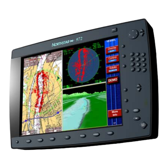
Marine website: www.northstarnav.com Checking the 972 package The Northstar 972 is a networked color GPS navigation family that you can connect to a wide variety of optional equipment, including the Northstar 491 echo sounder, Northstar radar, and VGA displays. Other optional interfaces include any NTSC- or PAL-compatible video sources, such as a video camera, TV, DVD, or VCR. - Page 6 DVI cable, 9-meter Owner registration card Limited warranty statement Parts kit (see Table 3) To connect multiple units, Ethernet cables must be purchased separately (see ”SECTION FOUR: Networking the Northstar 972” starting on page 17). Page 2 Part number 2301 957POD-CA...
- Page 7 Table 3: 972 Parts Kit contents (P/N 15-PK) Part name Spare fuse (7A fast-blow 5 x 20mm) Hex nut, 8-32, for flush-mounting Threaded stud, 8-32, for flush mounting Lockwasher, #8, for flush mounting Flat washer, #8, for flush mounting Table 4: 972 Optional equipment...
- Page 8 SECTION ONE: Introducing the 972 Page 4 972 Installation Manual, Rev. B...
-
Page 9: Section Two: Installing And Wiring The 972
WARNING! 972 Configuration The Northstar 972 uses a processor module that must be mounted in a protected location and a control head that can be exposed to water splash. A DVI video cable and a control cable feeds communication between the processor and the control head. All interface wiring connects to the processor. -
Page 10: Mounting The Control Head
The display screen is high-contrast and anti-reflective, and is viewable in direct sunlight, but for best results, install the 972 out of direct sunlight. The chosen location should have minimal glare from windows or bright objects. -
Page 11: Mounting The Processor
Mounting the Processor The processor should be installed in an accessible, dry location where cabling can be accessed and suitable ventilation is present. See the 972 Processor Mounting Template (P/N GT972) for hole locations and clearance requirements. It is absolutely necessary to mount the processor in a horizontal position as shown in Figure 2 so that the unit’s heat management system will work correctly. -
Page 12: Wiring The 972
Dimensions in inches Wiring the 972 Avoiding cable wiring shortcuts Most installation problems are caused by shortcuts taken with system cables. When wiring the 972, follow the guidelines below. DON’T DO THIS! • Don’t make sharp bends in the cables •... - Page 13 Interface connectors are shown in Figure 4: ”Processor connectors,” below. The functions of these connectors are described in Table 6. Interfacing is described in detail in Section Six, beginning on page 23. 972 Installation Manual, Rev. B Connector function(s) Control signals to and from...
- Page 14 SECTION TWO: Installing and wiring the 972 NMEA Connector GPS Connector (18-pin) (7-pin) VGA Output Wiring between the black box and the control head (shown below) is critical for proper operation. Never attempt to splice these cables. If necessary, use the available longer cables.
- Page 15 32 VDC maximum, using at least 16-gauge connecting wire. Connecting the 972 to ship’s power The 972 is shipped with 10-foot power cables for the processor and control head that you can lengthen to a maximum of 25 feet: •...
- Page 16 SECTION TWO: Installing and wiring the 972 If you lengthen the power cable, use an external fuse at the battery end as an added safety precaution. The fuse size should be chosen to be appropriate for the size of the smallest conductor in the circuit.
-
Page 17: Section Three: Installing And Wiring The Gps Antenna
2301’s view of the sky (the 2301 can use satellites nearly as low as the horizon). 972 Installation Manual, Rev. B SECTION THREE: Installing and wiring the GPS antenna Figure 6: 2301 GPS Antenna Do not open the 2301: There aren’t any serviceable parts inside. - Page 18 Page 14 Before permanently installing the 2301, try temporarily installing it and using the 972 to see if the location works well (see “Checking satellite status” beginning on page 21 to determine whether or not the selected location provides good reception).
- Page 19 3. Hole in mounting extension 4. Mounting adapter 5. Base of 2301 6. 2301 connector 7. Top of 2301 (antenna) 972 Installation Manual, Rev. B To install the 2301: Install a 1” x 14 UNF thread antenna mount in the desired location.
- Page 20 7. Heat the shrink tubing until it shrinks around the connector, providing a watertight seal. For the pin numbers and functions for the 972 end of the cable, see Table 7 below. TABLE 7: Wiring connections for 2301 cable Description...
-
Page 21: Section Four: Networking The Northstar 972
Waypoint and route transfer between a 972 and a Northstar 951, 952, 957, 958 or 6000i is accomplished using the AUX port as described in “Using the Aux Port” starting on page 29. -
Page 22: Technical Details
Technical details The networking port found on the Northstar 972 devices conforms to the electrical specifications set forth by the IEEE 802.3u 100Base-TX standard. This standard is also referred to as “Fast Ethernet. ”... -
Page 23: Ethernet Switches
Any standard 10/100 Mbit Ethernet switch can be used. These devices generally come with a “Wall Wart” type of a power adapter which is plugged into a 110V AC power outlet. The Northstar 972 has been tested with the following Ethernet switches using standard Category 5 cables:... - Page 24 SECTION FOUR: Networking the Northstar 972 Page 20 972 Installation Manual, Rev. B...
-
Page 25: Section Five: Checking Out The System
SECTION FIVE: Checking out the system Turning the 972 on and off To turn on the 972, gently and briefly press the PWR key. The unit emits several short beeps as it displays the screen, then performs a series of self-tests to check its critical components and start-up functions. -
Page 26: Installation-Test Checklist
33 to 51. For example, the satellite for the Atlantic Operating Region (AOR) is PRN 122, which the 972 displays as 35. See Table 8 below for the identification numbers for WAAS satellites that may be displayed on the screen. -
Page 27: Section Six: Interfacing The 972 System
SECTION SIX: Interfacing the 972 system This section describes the use of the NMEA, AUX, VGA and VIDEO connections. For Networking using the Ethernet connections, see “SECTION FOUR: Networking the Northstar 972” beginning on page 17. A typical fully-loaded system with all options installed might be wired as follows:. -
Page 28: The Nmea Connector
SECTION SIX: Interfacing the 972 system The NMEA connector The 972’s NMEA connector contains the following functions: NMEA Port 1, NMEA Port 2, and the RS-232 Port. Wiring the NMEA connector pins Description NMEA port 1 input A NMEA port 1 input B... - Page 29 OUTPUT DATUM (see page 28) Choosing the output format The 972 outputs navigation data in any of several standard formats as required by the receiving, or “listener,” device. The Output format • None turns the outputs off for when the 972 isn’t connected to an external device.
- Page 30 The NMEA 0183 standard requires that the equipment you’re interfaced to—the “listener”—knows what type of device is transmitting the data. The 972’s talker ID tells the listener that it is receiving information from a navigation source, not a communications or sensor device—which transmits completely different forms of data.
- Page 31 0183 and other formats can only function with two-place precision. Choosing the output rate The default rate for standard NMEA 0183 output is two seconds. The 972 lets you use a one-second update interval, a rate of 1 Hz, under limited circumstances, for NMEA and diagnostic data output.
-
Page 32: Configuring The Rs-232 Port
Some older devices may not accept sentences containing the NMEA 0183 checksum that’s output by the 972. In such cases, the device may not work properly or at all. If you have problems interfacing to older equipment, you can turn off the NMEA 0183 checksum: At the screen, press the cursor pad to highlight the cursor pad to change the setting from On to Off, then press ENTER. -
Page 33: Using The Aux Port
ENTER. NOTES: Using the “PORT OFF” setting Use this setting to reduce the loading on 972’s the processor when you don’t need the RS-232 port’s input or output functions. Using the Aux Port The 972’s Aux Port is used to connect with the optional 491 echo sounder, or for transferring the database of routes and waypoints between the 972 and many older Northstar units. - Page 34 6-pin solder-cup style cable connectors (P/N KS672). This data-transfer cable is not included. You must select a cable; use only shielded, twisted pair. To connect a 972 with a Northstar 952, 951, or 941, the older unit must be using software version 3.12 or higher.
- Page 35 7. Install the strain-relief clamp with two screws. 8. Connect one end of the cable to the Aux Port at the back of the 972, and the other end into the Aux Port at the back of the older unit.
- Page 36 SECTION SIX: Interfacing the 972 system Table 12: 957/958-to-972 wiring 957/958 Pin # 952/951/941 10-PIN AUX CONNECTOR No connect No connect No connect No connect Aux input B Ground/shield Aux output B Aux input A Aux output A No connect...
-
Page 37: Connecting The 972 To A Remote Display
Table 13: 952/951/941 to 972 wiring 952, 951, 941 Pin # *Pins 1, 2, 3, 4 and 10 on the 941/951/952 aux connector, and pin 2 on the 972 aux Connecting the 972 to a remote display The 972’s VGA connector is used to connect it with a remote display. A standard VGA cable is used. - Page 38 SECTION SIX: Interfacing the 972 system Page 34 972 Installation Manual, Rev. B...
-
Page 39: Section Seven: Troubleshooting And Servicing The 972 System
972 Installation Manual, Rev. B SECTION SEVEN: Troubleshooting and servicing the 972 system Make sure that the 972 doesn’t interfere with any other on-board systems. Check all other systems to ensure that their performance doesn’t degrade when the 972 is turned on. -
Page 40: Getting Technical Support
You can reach Northstar’s Service Department by e-mail, fax, U.S. mail, or phone as described in Table 14 below. Northstar’s Service Department is available between 9:00 AM and 5:00 PM Eastern Time, Monday through Friday, excluding major holidays. -
Page 41: Hearing From You
Product Manuals or Support links). Hearing from you Your feedback is important and helps Northstar ensure that this manual is a valuable resource for all marine technicians. E-mail your comments or suggestions about this manual to the following address: manuals@BNTMarine.com. - Page 42 972 users should contact their respective dealer for software updates. Northstar does not recommend that operators install software updates. If an update is installed incorrectly by mistake, you may lose data and the 972 may not work properly. Software updates aren’t covered by the Northstar warranty. Returning a 972 for service 972 repairs are performed only by authorized Northstar dealers or at the Northstar factory.
- Page 43 The 972 should be shipped only in a properly designed carton with packing material, and sent to the Northstar factory at the following address: Northstar Service Department, 30 Sudbury Road, Acton, MA 01720 USA.
- Page 44 SECTION SEVEN: Troubleshooting and servicing the 972 system Page 40 972 Installation Manual, Rev. B...
-
Page 45: Appendix A: 972 Technical Specifications
Two bi-directional NMEA I/O ports, 1 AUX port One bi-directional RS-232 port Interfaces to optional Northstar 491 for fishfinding or to an optional Northstar radar Waypoint upload/download capability to a PC (with appropriate software) or to older Northstar units on non-networked 972 units... - Page 46 APPENDIX A: 972 technical specifications Page 42 972 Installation Manual, Rev. B...