
Related Manuals for ABB AC31


Summary of Contents for ABB AC31
- Page 1 ASSEMBLY AND OPERATION MANUAL AC31 Adapter Supplement to the Existing Documentation...
-
Page 2: Table Of Contents
Table of contents — Table of contents AC31 Adapters..............................3 1.1 Introduction..............................3 1.2 Overview of AC31 adapters (replacement devices).................. 3 1.3 System data and CS31 bus system data....................4 1.3.1 System data of the AC31 adapters.................... 4 1.3.2 CS31 bus system data......................10 1.4 Replacement devices: CPU........................ -
Page 3: Ac31 Adapters
Note regarding During the development of the AC31 adapter series, care was taken to keep the device configu- product docu- ration identical to the configuration of the AC31 devices. Consequently, the technical documents... -
Page 4: System Data And Cs31 Bus System Data
AC31 Adapters System data and CS31 bus system data > System data of the AC31 adapters Existing devices: AC31 Replacement devices: AC31 Replacement device is based (90 series) adapters on the following AC500 device I/O modules: 07DC91 07DC91-AD DC532 07DC92... - Page 5 AC31 Adapters System data and CS31 bus system data > System data of the AC31 adapters £ 5 % Residual ripple Polarity reversal protection 10 s (test duration), perma- nently present on AC31 adapters Bridging time for power interruptions according to IEC 61131-2: DC supply Interruption <...
- Page 6 AC31 Adapters System data and CS31 bus system data > System data of the AC31 adapters Table 4: AC voltage tests Data Voltage Duration 24 V circuits (supply, 24 V inputs/outputs), when electri- 350 VAC 60 s cally isolated from other circuitry...
- Page 7 AC31 Adapters System data and CS31 bus system data > System data of the AC31 adapters Data Value -> Digital inputs/outputs 1 kV -> Analog inputs/outputs 1 kV -> CS31 system bus 1 kV -> Serial RS-232 interfaces (COM) 1 kV ->...
- Page 8 AC31 Adapters System data and CS31 bus system data > System data of the AC31 adapters Fig. 1: Earthing of devices 07AC91-AD, 07AC91-AD2, 07AI91-AD, 07DC91-AD and 07DC92-AD 3ADR010122, 8, en_US 2018/09/24...
- Page 9 Fig. 3: CPU earthing When earthing the replacement devices, observe the following: ● Install the AC31 adapter devices onto an earthed mounting plate to ensure a uniform refer- ence potential of all equipment. ● Implement the connections between switchgear cabinet, mounting plate, PE rail and shield rail with low impedance.
-
Page 10: Cs31 Bus System Data
AC31 Adapters System data and CS31 bus system data > CS31 bus system data ● Install the lines in groups (power lines, power supply lines, signal lines, data lines). ● Use lines with braided cable shield for analog signals. Earth the shield on both sides and make sure that no compensation currents flow through the cable shield. - Page 11 AC31 Adapters System data and CS31 bus system data > CS31 bus system data Possible CS31 slaves: ● 07AC91-AD, 07AC91 ● 07AC91-AD2 ● 07AI91-AD, 07AI91 ● 07DC91-AD, 07DC91 ● 07DC92-AD, 07DC92 ● DC501-CS31-AD, DC501-CS31 The following diagram shows the bus topology without shielding and earthing treatment: Fig.
- Page 12 AC31 Adapters System data and CS31 bus system data > CS31 bus system data Incorrect cable laying: 1.3.2.3 Earthing In order to avoid disturbances, earth the cable shields directly. Current carrying Choose direct earthing if it can be ensured by means of current carrying metal connections capacity (steel constructions, earth bars, etc.) that no potential differences can occur.
- Page 13 AC31 Adapters System data and CS31 bus system data > CS31 bus system data Fig. 6: Direct earthing of CS31 bus master and CS31 slave The shield connection of the CS31 bus master is internally connected to the earth terminal.
- Page 14 AC31 Adapters System data and CS31 bus system data > CS31 bus system data 1.3.2.4 Bus cycle time and data security The communication via the CS31 bus is cyclic and controlled by the CS31 bus master. Fig. 8: Format of request telegram of a CS31 bus master...
- Page 15 AC31 Adapters System data and CS31 bus system data > CS31 bus system data Table 7: Example: Bus cycle time Base time Min. update time = 5 ms 5000 µs Bus transmission time Receiving 16 byte 16 x 43 µs 688 µs...
- Page 16 Diagnosis system of the AC500 series For further information on both mechanisms, please refer to the AC500 documentation. Below, only a few special diagnosis functions of the AC31 adapter are addressed. Function block In the 'State' column, the variable byStateDiag of the structure strCS31_DiagOneModule is CS31_DIAG: indicated for every CS31 bus slave.
- Page 17 AC31 Adapters System data and CS31 bus system data > CS31 bus system data Fig. 15: Visualization: CS31 bus diagnosis Table 8: Interpretation of variable byStateDiag Value Description CS31 bus slave disconnected Not used slave on CS31 bus bus not...
-
Page 18: Replacement Devices: Cpu
The acknowledgment of a CS31 bus slave error can take place via the CS31 bus master by means of the function block CS31QU_EXT (see AC500 documentation). 1.4 Replacement devices: CPU For AC31 devices of the 90 series, AC31 adapters (replacement devices) are available for the exchange of the CPU. 3ADR010122, 8, en_US... -
Page 19: Replacement Device 07Kt9X-Ad
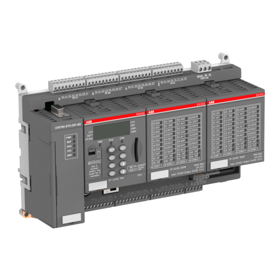
1.4.1 Replacement device 07KT9x-AD 1.4.1.1 Introduction Fig. 16: 3ADR331183S0015 The replacement device versions 07KT9x-AD of the AC31 adapter series replace the existing devices 07KT94 and 07KT98 of the AC31 devices of the 90 series. Versions: ● 07KT94-ARC-AD: I/O module DA501, I/O module DA502, CPU EC581 ●... - Page 20 AC31 Adapters Replacement devices: CPU > Replacement device 07KT9x-AD Ä Chapter 1.3 “System data and CS31 bus Please observe the system data for CS31 bus system data” on page 4. For general information on the CPU, please refer to the AC500 documentation.
- Page 21 AC31 Adapters Replacement devices: CPU > Replacement device 07KT9x-AD Planning/ com- Software Automation Builder (see AC500 documentation): missioning ● 07KT98-ARC-AD ● 07KT98-ARC-DP-AD ● 07KT98-ARC-ETH-AD ● 07KT98-ETH-DP-AD ● 07KT98-ARC-ETH-DP-AD Software 907PC331 ● 07KT94-ARC-AD 1.4.1.2.2 Functionality Table 10: Existing device vs. replacement device...
- Page 22 AC31 Adapters Replacement devices: CPU > Replacement device 07KT9x-AD Designation Existing device: Replacement device: Note 07KT98 07KT9x-AD Serial Interfaces COM1, COM2 as COM2 (programming The serial COM1 Modbus interfaces, for function, test function, interface of 07KT9x is programming and test free protocol) no longer available.
- Page 23 AC31 Adapters Replacement devices: CPU > Replacement device 07KT9x-AD Ä Further information on page 25 Table 11: Comparison: Replacement device versions 07KT94- 07KT98- 07KT98- 07KT98- 07KT98- 07KT98- ARC-AD ARC-AD ARC-DP- ARC-ETH- ETH-DP- ARC-ETH- DP-AD ARCNET PROFIBUS - Ethernet CS31 Parallel...
- Page 24 AC31 Adapters Replacement devices: CPU > Replacement device 07KT9x-AD Description Hole for screw mounting (screw diameter 4 mm, extension torque 1.2 Nm) Digital inputs/outputs for DA502 Digital inputs for DA501 Digital inputs for DA501 Analog inputs for DA501/DA502 CS31 bus Interface...
- Page 25 AC31 Adapters Replacement devices: CPU > Replacement device 07KT9x-AD 1.4.1.3.1 Electrical connection Fig. 18: Terminal assignment 07KT9x-AD DIAG No electrical isolation (M) COM2 Electrically isolated CS31 bus Electrically isolated Ethernet Electrically isolated ARCNET Electrically isolated DA501/DA502 Electrically isolated Ä Chapter 1.3.1.7 “Earthing” on page 7.
- Page 26 AC31 Adapters Replacement devices: CPU > Replacement device 07KT9x-AD Connection of the supply voltage Fig. 19: Connection of the supply voltage Table 12: Connector (X6) Connector / Terminal Assignment / Signal X6 / L+ Supply voltage +24 V DC X6 / L+...
- Page 27 AC31 Adapters Replacement devices: CPU > Replacement device 07KT9x-AD If 07KT9x-AD is connected to one of the bus ends, a 120 Ω resistor must be connected for bus termination. The device 07KT9x-AD always functions as master. Slave operation is not possible.
- Page 28 AC31 Adapters Replacement devices: CPU > Replacement device 07KT9x-AD Fig. 20: Arrangement of the 16 digital inputs The digital input states are always indicated by the LEDs DI0-DI15: Fig. 21: DA501 LED status indication Characteristics of the digital inputs: ●...
-
Page 29: Table 16: Connector (X7
AC31 Adapters Replacement devices: CPU > Replacement device 07KT9x-AD Fig. 22: Circuit arrangement of DA501 module Connection of the digital outputs Ä Further information on page 25. Table 16: Connector (X7) Connector / Terminal Assignment / Signal X7 / ZP X7 / 1.0... - Page 30 AC31 Adapters Replacement devices: CPU > Replacement device 07KT9x-AD Connector / Terminal Assignment / Signal X8 / 2.7 DA502 / DO15 X8 / UP Fig. 23: Arrangement of digital outputs Characteristics of the digital outputs ● The digital output states are always indicated by the LEDs DO0-DO15 on DA501 module.
- Page 31 AC31 Adapters Replacement devices: CPU > Replacement device 07KT9x-AD Table 19: Connector (X9) Connector / Terminal Assignment / Signal X9 / ZP X9 / 8.0 DA501 / DC16 X9 / 8.1 DA501 / DC17 X9 / 8.2 DA501 / DC18 X9 / 8.3...
- Page 32 AC31 Adapters Replacement devices: CPU > Replacement device 07KT9x-AD Characteristics of the digital inputs/outputs ● The digital input/output states are always indicated via the LEDs DC16 - DC23 on DA501 or DA502. ● All 16 inputs/outputs have the same potential ZP as all other inputs/outputs. The electrical isolation included in the existing devices is no longer available.
- Page 33 AC31 Adapters Replacement devices: CPU > Replacement device 07KT9x-AD Connector / Terminal Assignment / Signal X4 / 3.1 DA502 / AI1+ X4 / 3.2 DA502 / AI2+ X4 / 3.3 DA502 / AI3+ X4 / 7.0 DA501 / AI0+ X4 / 7.1 DA501 / AI1+ X4 / 7.2...
- Page 34 AC31 Adapters Replacement devices: CPU > Replacement device 07KT9x-AD Reference to earth ZP: connect ZP to several connectors. In the example, ZP is connected to connector X3. Characteristics of the analog inputs: ● The 8 analog inputs are not electrically isolated. The internal PTC connection is connected to earth ZP (existing device: earth M).
- Page 35 AC31 Adapters Replacement devices: CPU > Replacement device 07KT9x-AD Measuring ranges Fig. 27: 07KT98_Measuring_Ranges ± 10 V / 0 ... 10 V Due to the internal electrical isolation of the sensor voltage supply, no change to the wiring is necessary.
- Page 36 AC31 Adapters Replacement devices: CPU > Replacement device 07KT9x-AD Fig. 28: Voltage input with externally supplied 3-wire voltage sensors 3ADR010122, 8, en_US 2018/09/24...
- Page 37 AC31 Adapters Replacement devices: CPU > Replacement device 07KT9x-AD Measuring ranges (passive two pole sen- sors) Fig. 29: Connection of current sensors 4 ... 20 mA to the analog inputs If the analog current sensors 4 ... 20 mA are supplied from a separate power supply unit, the 0 V/GND connection of the power supply unit must be con- nected to the ZP connection of the 07KT9x-AD.
- Page 38 AC31 Adapters Replacement devices: CPU > Replacement device 07KT9x-AD For further information on protective function, error indication and diagnosis, please refer to the AC500 documentation. Measuring range (active sensors with external supply) Fig. 30: Connection of current sensors 0 ... 20 mA to the analog inputs Please note that in the example the 0 V supply (ZP) must be used as reference potential.
- Page 39 AC31 Adapters Replacement devices: CPU > Replacement device 07KT9x-AD Measuring Table 21: Figure range range with Range Assigned figure range Pt100 2-wire -50 C ... 400°C -500 ... +4000 -50 C ... 70°C -500 ... +700 The following measuring ranges can be configured:...
- Page 40 AC31 Adapters Replacement devices: CPU > Replacement device 07KT9x-AD Fig. 31: Connection of Pt100 temperature sensors in 3-wire configuration In order to keep measuring errors as small as possible, it is necessary to have all the involved conductors in the same cable. All the conductors must have the same cross section.
- Page 41 AC31 Adapters Replacement devices: CPU > Replacement device 07KT9x-AD Fig. 32: Use of analog inputs as digital inputs Connection of the 4 configurable analog outputs Connector / Terminal Assignment / Signal X10 / AG.2 AGND2 X10 / 3.5 DA502 / AO0+ X10 / 3.6...
- Page 42 / 4 ... 20 mA Fig. 34: Connection of output loads (voltage and current) to analog outputs Battery and battery replacement The AC31 adapters use another battery (lithium battery TA521). For further information, please refer to the AC500 documentation. Serial interface COM1 The serial interface COM1 is no longer available.
- Page 43 AC31 Adapters Replacement devices: CPU > Replacement device 07KT9x-AD Connector / Pin Assignment / Signal COM2 / 4 COM2 / 5 COM2 / 6 Not connected COM2 / 7 Signal Ground COM2 / 8 Signal Ground COM2 / 9 +5 V The assignment of the serial interface COM2 has not changed.
- Page 44 Technical data 07KT9x-AD The technical data described in the existing documentation (chapter 2.2.7) are invalid for the AC31 adapter and are replaced by the following data. Ä Chapter 1.3 “System data and CS31 bus system data” on page 4 Further information:...
- Page 45 AC31 Adapters Replacement devices: CPU > Replacement device 07KT9x-AD Data Value Operating and error indications Display via LEDs and CPU display. For detailed information, please refer to the AC500 documentation. Connection technology Detachable screw-type terminal blocks Supply terminals, CS31 system bus max.
- Page 46 AC31 Adapters Replacement devices: CPU > Replacement device 07KT9x-AD Digital inputs Data Value Number of channels per device Connections Connector X2 (terminals X5.0…X5.7) Connector X3 (terminals X6.0…X6.7) Division of channels in groups 2 groups with 8 channels (not electrically iso-...
- Page 47 AC31 Adapters Replacement devices: CPU > Replacement device 07KT9x-AD Digital outputs Data Value Number of channels per device 16 high-side switches Connections Connector X7 (terminals 1.0 ... 1.7) Connector X8 (terminals 2.0 ... 2.7) Division of channels in groups 2 groups with 8 channels (not electrically iso-...
- Page 48 AC31 Adapters Replacement devices: CPU > Replacement device 07KT9x-AD Digital inputs/outputs Data Value Number of channels per device 16 inputs/outputs Connections Connector X1 (terminals 4.0 ... 4.7) Connector X9 (terminals 8.0 ... 8.7) Division of channels in groups 2 groups of 8 channels each Group 1: terminals 4.0 ...
- Page 49 AC31 Adapters Replacement devices: CPU > Replacement device 07KT9x-AD For further information, please refer to the existing documentation System description Advant Controller 31. Analog inputs Data Value Number of channels per device Connections Connector X4 (terminals 3.0 … 3.3 and 7.0…...
- Page 50 AC31 Adapters Replacement devices: CPU > Replacement device 07KT9x-AD Data Value Resolution in bits: -> Ranges ±10 V, 0 ... 10 V 12 bit plus sign -> Ranges 0 ... 20 mA, 4 ... 20 mA 12 bit without sign ->...
- Page 51 AC31 Adapters Replacement devices: CPU > Replacement device 07KT9x-AD Data Value Electrical isolation Fig. 18 ± 1 V Max. permissible potential difference between terminal ZP (minus the supply voltage) and Caution: The internal reference is no longer M terminals AGND (minus the analog inputs and but ZP.
- Page 52 AC31 Adapters Replacement devices: CPU > Replacement device 07KT9x-AD Data Value Program change 07KT94-ARC-AD: 907 PC 331 07KT98-ARC-AD: Automation Builder Man-Machine Communication Yes, e.g. via Automation Builder Electrical isolation Fig. 18 Potential differences In order to avoid potential differences between...
- Page 53 AC31 Adapters Replacement devices: CPU > Replacement device 07KT9x-AD LED display Data Value LEDs for signaling: -> State of digital inputs 1 yellow LED per channel -> State of digital outputs 1 yellow LED per channel -> State of digital inputs/outputs 1 yellow LED per channel ->...
- Page 54 AC31 Adapters Replacement devices: CPU > Replacement device 07KT9x-AD Ordering data Order No. Scope of delivery 1SAP 801 000 R0061 CPU: 07KT94-ARC-AD 1SAP 801 400 R0060 CPU: 07KT98-ARC-AD 1SAP 801 100 R0062 CPU: 07KT98-ARC-DP-AD 1SAP 801 200 R0067 CPU: 07KT98-ARC-ETH-AD...
- Page 55 AC31 Adapters Replacement devices: CPU > Replacement device 07KT9x-AD 1.4.1.3.6 PROFIBUS DP coupler Central units with an integrated PROFIBUS coupler: ● 07KT98-ARC-DP-AD ● 07KT98-ETH-DP-AD ● 07KT98-ARC-ETH-DP-AD Technical data Data Value Connector 9 pin SUB D socket PROFIBUS interface EIA RS-485 according to EN 50170...
-
Page 56: Replacement Devices: I/O Modules
The general information about the Ethernet system is still valid. For further information on Ethernet, please refer to the AC500 documentation. 1.5 Replacement devices: I/O modules For AC31 devices of the 90 series, AC31 adapters (replacement devices) are available for the exchange of individual I/O modules. 3ADR010122, 8, en_US... -
Page 57: Replacement Device 07Dc91-Ad
1.5.1 Replacement device 07DC91-AD Fig. 36: 3ADR331192S0015_07DC91-AD The replacement device 07DC91-AD of the AC31 adapter series replaces the existing device 07DC91 of the 90 series. During the development of the replacement device, care was taken to keep the device configu- ration identical to the configuration of the existing device. - Page 58 AC31 Adapters Replacement devices: I/O modules > Replacement device 07DC91-AD 1.5.1.1 Device configuration Fig. 37: 3ADR333196F0015_07DC91-AD_Front Description Connection for CS31 buss (X1) 8 digital inputs 24 V DC (X2) 8 digital inputs 24 V DC (X3) Hole for screw mounting (screw diameter 4 mm, extension torque 1.2 Nm)
- Page 59 AC31 Adapters Replacement devices: I/O modules > Replacement device 07DC91-AD 1.5.1.2 LED display Fig. 38: Front view: DC532 Displays of module 8 yellow LEDs to indicate the signal status of the digital inputs (X2). 8 yellow LEDs to indicate the signal status of the digital inputs (X3).
- Page 60 AC31 Adapters Replacement devices: I/O modules > Replacement device 07DC91-AD 1.5.1.3 Electrical connection Fig. 39: Electrical connection Table 26: Pin assignment CS31 bus (X1) Connector / Terminal Assignment / Signal X1 / Shield No internal connection X1 / B2 BUS 2...
- Page 61 AC31 Adapters Replacement devices: I/O modules > Replacement device 07DC91-AD Connector / Terminal Assignment / Signal X2 / 1.1 DC532 / I1 X2 / 1.2 DC532 / I2 X2 / 1.3 DC532 / I3 X2 / 1.4 DC532 / I4 X2 / 1.5...
- Page 62 AC31 Adapters Replacement devices: I/O modules > Replacement device 07DC91-AD Connector / Terminal Assignment / Signal X5 / 3.5 DC532 / C21 X5 / 3.6 DC532 / C22 X5 / 3.7 DC532 / C23 Table 31: Pin assignment 24 V DC 200 W (X4)
- Page 63 In the following, the information in the "Type" column refers to the data type designation of the Ä Chapter 1.3 “System data and CS31 bus system Automation Builder (see AC31 system data data” on page 4). The information in the "Type" column must be interpreted from the viewpoint of the CS31 bus master.
- Page 64 AC31 Adapters Replacement devices: I/O modules > Replacement device 07DC91-AD Byte Type Connector / Terminal 8 bit output (receive) 0 ... 7 X5 / 3.0 X5 / 3.1 X5 / 3.2 X5 / 3.3 X5 / 3.4 X5 / 3.5 X5 / 3.6...
- Page 65 AC31 Adapters Replacement devices: I/O modules > Replacement device 07DC91-AD Fig. 42: DIP switch for 07DC91-AD The DIP switches are read by the device only once after the supply voltage has been connected. For further information, please refer to the existing documentation System description Advant Controller 31.
- Page 66 AC31 Adapters Replacement devices: I/O modules > Replacement device 07DC91-AD The RAM is checked during the initialization of the device. In addition, the firmware in the Flash memory is checked by means of a checksum during initialization. When the control system (PLC/central unit) is stopped during normal operation, the outputs of the device 07DC91-AD are switched off.
- Page 67 AC31 Adapters Replacement devices: I/O modules > Replacement device 07DC91-AD The S-ERR LED remains on even if the error no longer occurs. The error must be confirmed by Ä Chapter 1.3 “System the control system (PLC/central unit), e.g. by means of a function block data and CS31 bus system data”...
- Page 68 AC31 Adapters Replacement devices: I/O modules > Replacement device 07DC91-AD Fig. 43: Front view: DC532 1.5.1.8 Technical data This section provides additional information on section Ä Chapter 1.3 “System data and CS31 bus system data” on page 4. In case of doubt, the following information applies.
- Page 69 AC31 Adapters Replacement devices: I/O modules > Replacement device 07DC91-AD For further information, please refer to the existing documentation System description Advant Controller 31. CAUTION! System damage caused by voltage! Exceeding the maximum supply or process voltage (>30 V DC) results in per- manent system damage (destruction).
- Page 70 AC31 Adapters Replacement devices: I/O modules > Replacement device 07DC91-AD Data Value Input voltage +30 V Replacement device: < 8 mA Existing device: £ 9 mA Maximum cable length: -> Shielded 1000 m -> Unshielded 600 m Protection against reversed voltage...
- Page 71 AC31 Adapters Replacement devices: I/O modules > Replacement device 07DC91-AD Fig. 44: Protective circuits inputs/outputs Due to the changed protective circuit on the inputs and outputs, the restrictions concerning the input signal voltage described in the existing documentation no longer apply.
-
Page 72: Replacement Device 07Dc92-Ad
1.5.2 Replacement device 07DC92-AD Fig. 45: 3ADR333196F0015_07DC92-AD The replacement device 07DC92-AD of the AC31 adapter series replaces the existing device 07DC92 of the 90 series. During the development of the replacement device, care was taken to keep the device configu- ration identical to the configuration of the existing device. - Page 73 AC31 Adapters Replacement devices: I/O modules > Replacement device 07DC92-AD This document adds the following points to the still valid existing documentation: ● Unavoidable device deviations, e.g. due to technical limitations. ● Expansion of documentation as a result of normative requirements.
- Page 74 AC31 Adapters Replacement devices: I/O modules > Replacement device 07DC92-AD 1.5.2.2 LED display Fig. 47: LEDs DO524 Displays of module 8 yellow LEDs to indicate the signal status of the digital inputs/outputs (X2). 8 yellow LEDs to indicate the signal status of the digital inputs/outputs (X3).
- Page 75 AC31 Adapters Replacement devices: I/O modules > Replacement device 07DC92-AD 1.5.2.3 Electrical connection Fig. 48: Electrical connection Table 37: Pin assignment CS31 bus (X1) Connector / Terminal Assignment / Signal X1 / Shield No internal connection X1 / B2 BUS 2...
- Page 76 AC31 Adapters Replacement devices: I/O modules > Replacement device 07DC92-AD Connector / Terminal Assignment / Signal X2 / 1.1 DO524 / O1 X2 / 1.2 DO524 / O2 X2 / 1.3 DO524 / O3 X2 / 1.4 DO524 / O4 X2 / 1.5...
- Page 77 AC31 Adapters Replacement devices: I/O modules > Replacement device 07DC92-AD Connector / Terminal Assignment / Signal X5 / 3.7 DO524 / O23 X5 / UP/L+ UP/L+ Table 42: Pin assignment DC (X6) Connector / Terminal Assignment / Signal X6 / ZP/M ZP/M X6 / 4.0...
- Page 78 In the following, the information in the "Type" column refers to the data type designation of the Ä Chapter 1.3 “System data and CS31 bus system Automation Builder (see AC31 system data data” on page 4). The information in the "Type" column must be interpreted from the viewpoint of the CS31 bus master.
- Page 79 AC31 Adapters Replacement devices: I/O modules > Replacement device 07DC92-AD Fig. 50: DIP switch for 07DC92-AD: The DIP switches are read by the device only once after the supply voltage has been connected. For further information, please refer to the existing documentation System description Advant Controller 31.
- Page 80 AC31 Adapters Replacement devices: I/O modules > Replacement device 07DC92-AD ● After successful initialization of the CS31 bus communication, the CS31 bus LED lights up. The S-ERR LED goes out. ● During operation, the yellow LEDs indicate the signal statuses of the channels.
- Page 81 AC31 Adapters Replacement devices: I/O modules > Replacement device 07DC92-AD Special cases with rapidly flashing LEDs (approx. 5 Hz): ● All 4 LEDs flash rapidly: An incorrect S500 module is connected to the device. The device fails to initialize. ●...
- Page 82 AC31 Adapters Replacement devices: I/O modules > Replacement device 07DC92-AD Fig. 51: LEDs DO524 1.5.2.8 Technical Data This section provides additional information on section Ä Chapter 1.3 “System data and CS31 bus system data” on page 4. In case of doubt, the following information applies.
- Page 83 AC31 Adapters Replacement devices: I/O modules > Replacement device 07DC92-AD Data Value Power consumption Replacement device: 200 W Existing device: 394 W Max. power dissipation within the module (out- Replacement device: 6 W puts unloaded) Existing device: 5 W Address setting and configuration...
- Page 84 AC31 Adapters Replacement devices: I/O modules > Replacement device 07DC92-AD Fig. 53: Process voltage connections - 07DC92-AD NOTICE! Process voltage must always be connected to connector X4 on device 07DC92- Connector X4 also supplies the internal electronics for the device 07DC92-AD with 0.15 A.
- Page 85 AC31 Adapters Replacement devices: I/O modules > Replacement device 07DC92-AD Data Value Input delay: 0 -> 1 or 1 -> 0 *) Replacement device: Type. 8 ms Existing device: Type. 7 ms Indication of the input signals Replacement device: One yellow LED per channel.
- Page 86 AC31 Adapters Replacement devices: I/O modules > Replacement device 07DC92-AD 1.5.2.8.3 Technical details of the I/O channels as digital outputs Data Value Connections X2 / 1.0 to 1.7 X3 / 2.0 to 2.7 X5 / 3.0 to 3.7 X6 / 4.0 to 4.7...
- Page 87 AC31 Adapters Replacement devices: I/O modules > Replacement device 07DC92-AD 1.5.2.8.4 Connection to the CS31 bus Data Value Connections X1/B2, X1/B1 CS31 bus type 04 (digital input/output) Termination resistor Not available (must be provided externally if needed) 1.5.2.8.5 Mechanical data...
-
Page 88: Replacement Device 07Ai91-Ad
1.5.3.1 Introduction Fig. 55: 3ADR331191S0015_07AI91-AD The replacement device 07AI91-AD from the AC31 adapter series replaces the existing device 07DC91 from the 90 series. During the development of the replacement device, care was taken to keep the device configu- ration identical to the configuration of the existing device. Thus, the existing documentation of device 07AI91 remains valid and serves as a reference (system description Advant Controller 31). - Page 89 AC31 Adapters Replacement devices: I/O modules > Replacement device 07AI91-AD 1.5.3.2 Device configuration Fig. 56: Front view: 07AI91-AD Description Connection for CS31 bus (X1) Analog inputs (X2) 2.5 AI (± 10 V differential, ± 5 V differential, temperature measurement PT100 / PT1000, 4…20 mA and 0…20 mA with external resistor)
- Page 90 AC31 Adapters Replacement devices: I/O modules > Replacement device 07AI91-AD In contrast to the existing device, the following measuring ranges are not avail- ± 500 mV, ± 50 mV. Temperature measurement able in the replacement device: with thermocouples is also not possible.
- Page 91 AC31 Adapters Replacement devices: I/O modules > Replacement device 07AI91-AD 1.5.3.2.2 Electrical connection Fig. 58: Electrical connection 1) Electrical isolation 2) Switchgear cabinet earthing Please observe the following information: ● The Shield connections of the CS31 bus and FE of the supply voltage have no connection within the device.
- Page 92 AC31 Adapters Replacement devices: I/O modules > Replacement device 07AI91-AD Connector / Terminal Assignment / Signal X2 / 2.3 AI523 / I3+ X2 / 2.2 AI523 / I2+ X2 / 1.4 AI523 / I4- (AGND1) X2 / 2.5 AI523 / I5+ X2 / 2.4...
- Page 93 AC31 Adapters Replacement devices: I/O modules > Replacement device 07AI91-AD Connector / Terminal Assignment / Signal X6 / 4.7 AI523 / I15+ X6 / 4.6 AI523 / I14+ X6 / NC Not connected X6 / NC Not connected In module AI523, the signals I8-, I10-, I12- and I14- are internally connected to an analog earth.
- Page 94 AC31 Adapters Replacement devices: I/O modules > Replacement device 07AI91-AD Analog signal lines must be routed in shielded cables. The shield must be earthed on both sides and should be earthed to replacement device and signal source / signal sink as close as possible.
- Page 95 AC31 Adapters Replacement devices: I/O modules > Replacement device 07AI91-AD Fig. 61: Resistance thermometer 1) Return conductor 2) Twisted wire pair in the cable (*) 3-wire For temperature measurements with PT100/PT1000 resistors, the wiring to the existing device must be changed. A 4-wire temperature measurement is not possible with the replacement device.
- Page 96 AC31 Adapters Replacement devices: I/O modules > Replacement device 07AI91-AD Fig. 62: DIP switch for 07AI91-AD The function of the address DIP switch 8 (channel No. £ 7 or channel No. > 7) is not supported for the replacement device. This DIP switch must be switched off.
- Page 97 AC31 Adapters Replacement devices: I/O modules > Replacement device 07AI91-AD Fig. 63: "Configuration pair" not used 1) Channel 0 and channel 1 are not used -> DIP switch "No evaluation of channels" If both channels of a "configuration pair" are not used, set the DIP switches to "No evaluation of channels".
- Page 98 AC31 Adapters Replacement devices: I/O modules > Replacement device 07AI91-AD Fig. 64: Only one channel of a "configuration pair" is used 1) Electrically isolated power supply of analog sensor 2) Earthing at sensor 3) Channel not used ± 10 V, ± 5 V at differential inputs If only one channel of a "configuration pair"...
- Page 99 In the following, the information in the "Type" column refers to the data type designation of the Ä Chapter 1.3 “System data and CS31 bus system Automation Builder (see AC31 system data data” on page 4). The information in the "Type" column must be interpreted from the viewpoint of the CS31 bus master.
- Page 100 AC31 Adapters Replacement devices: I/O modules > Replacement device 07AI91-AD Table 54: CS31 bus Type Byte Connector / Terminal WORD input (send) 0 X2 / 2.1, X2 / 2.0 WORD input (send) 1 X2 / 2.3, X2 / 2.2 WORD input (send) 2 X2 / 2.5, X2 / 2.4...
- Page 101 AC31 Adapters Replacement devices: I/O modules > Replacement device 07AI91-AD The replacement device does not provide a test button to measure functionality. Table 55: Diagnosis information of the CS31 bus Channel Error code (COD- Error code (CS31 Description ESYS) bus bus)
- Page 102 AC31 Adapters Replacement devices: I/O modules > Replacement device 07AI91-AD Special cases with rapidly flashing LEDs (approx. 5 Hz): ● All 4 LEDs flash rapidly: An incorrect S500 module is connected to the device. The device fails to initialize. ●...
- Page 103 AC31 Adapters Replacement devices: I/O modules > Replacement device 07AI91-AD Fig. 65: 07AI91-AD_Front 1.5.3.2.8 Technical data Ä Chapter 1.3 “System data and CS31 This section provides additional information on section bus system data” on page 4. In case of doubt, the following information applies.
- Page 104 AC31 Adapters Replacement devices: I/O modules > Replacement device 07AI91-AD For further information, please refer to the existing documentation System description Advant Controller 31. CAUTION! System damage caused by voltage! Exceeding the maximum supply or process voltage (>30 V DC) results in per- manent system damage (destruction).
- Page 105 AC31 Adapters Replacement devices: I/O modules > Replacement device 07AI91-AD Data Value 12 bit + sign (measuring range ± 10 V) Resolution 11 bit + sign (measuring range ± 5 V) Replacement device: ± 1 % of full range value Total error Existing device: ±...
- Page 106 AC31 Adapters Replacement devices: I/O modules > Replacement device 07AI91-AD Connection to the CS31 bus Data Value Connections X1 / B2, X1 / B1 CS31 bus type 01 (analog input) Termination resistor Not available (must be provided externally if needed)
-
Page 107: Replacement Device 07Ac91-Ad
Fig. 66: 3ADR331193S0015_07AC91-AD The replacement device 07AC91-AD of the AC31 adapter series replaces the existing device 07AC91 of the AC31/90 series in operating mode 8 bit. The replacement device 07AC91-AD2 is available for operating mode 12 bit. During the development of the replacement device, care was taken to keep the device configu- ration identical to the configuration of the existing device. - Page 108 AC31 Adapters Replacement devices: I/O modules > Replacement device 07AC91-AD 1.5.4.2 Device configuration Fig. 67: Front view: 07AC91-AD Description Connection for CS31 bus (X1) Analog outputs (X2): 0 ... 10 V, 0 ... 20 mA Analog outputs (X3): 0 ... 10 V Hole for screw mounting (screw diameter 4 mm, extension torque 1.2 Nm)
- Page 109 AC31 Adapters Replacement devices: I/O modules > Replacement device 07AC91-AD 1.5.4.2.1 LED display The LED display on the replacement device is changed: Fig. 68: AO523 Display of module 8 yellow LEDs to indicate the signal status of the analog inputs (X2 and X3)
- Page 110 AC31 Adapters Replacement devices: I/O modules > Replacement device 07AC91-AD 1.5.4.2.2 Electrical connection Fig. 69: Electrical connection Please observe the information contained in the existing documentation. In sec- tion "Fig. 5.4-2: Electrical connection of the analog input/output module 07AC91", only the information concerning operating mode 8 bit is relevant for the replacement device 07AC91-AD.
- Page 111 AC31 Adapters Replacement devices: I/O modules > Replacement device 07AC91-AD Table 59: Pin assignment AO (X2) Connector / Terminal Assignment / Signal X2 / 2.0 AO523 / O0+ X2 / 1.0 AO523 / O0- (AGND) X2 / 2.1 AO523 / O1+ X2 / 1.1...
- Page 112 AC31 Adapters Replacement devices: I/O modules > Replacement device 07AC91-AD Connector / Terminal Assignment / Signal X6 / 4.2 AO523 / O10+ X6 / 3.2 AO523 / O10- (AGND) X6 / 4.3 AO523 / O11+ X6 / 3.3 AO523 / O11- (AGND)
- Page 113 AC31 Adapters Replacement devices: I/O modules > Replacement device 07AC91-AD Fig. 71: Current output Analog signal lines must be routed in shielded cables. The shield must be earthed on both sides and should be earthed to replacement device and signal source / signal sink as close as possible.
- Page 114 AC31 Adapters Replacement devices: I/O modules > Replacement device 07AC91-AD Fig. 72: DIP switch for 07AC91-AD Please observe the following: ● All channels must be configured as outputs. The function of the address DIP switch 8 (channel No. £ 7 or channel No. > 7) is no longer ●...
- Page 115 In the following, the information in the "Type" column refers to the data type designation of the Ä Chapter 1.3 “System data and CS31 bus system Automation Builder (see AC31 system data data” on page 4). The information in the "Type" column must be interpreted from the viewpoint of the CS31 bus master.
- Page 116 AC31 Adapters Replacement devices: I/O modules > Replacement device 07AC91-AD The RAM is checked during the initialization of the device. In addition, the firmware in the Flash memory is checked by means of a checksum during initialization. When the control system (PLC/central unit) is stopped during normal operation, the outputs of the device are switched off.
- Page 117 AC31 Adapters Replacement devices: I/O modules > Replacement device 07AC91-AD ● The LEDs of the S-ERR bus and I/O bus flash rapidly: A checksum error occurred in an internal Flash memory. ● The LED of the I/O bus flashes rapidly: An error occurred in an internal RAM.
- Page 118 AC31 Adapters Replacement devices: I/O modules > Replacement device 07AC91-AD Technical Data of the complete device Data Value Process voltage: -> Connections X4/L+ (pin 20), X4/L+ (pin 21), X4/M (pin 22), X4/M (pin 23) -> Fuse for L+ 10 A, fast acting...
- Page 119 AC31 Adapters Replacement devices: I/O modules > Replacement device 07AC91-AD Technical Data of the analog outputs Data Value Connections X2 / 2.0, X2 / 2.1, X2 / 2.2, X2 / 2.3, X3 / 2.4, X3 / 2.5, X3 / 2.6, X3 / 2.7, X6 / 4.0, X6 / 4.1, X6 / 4.2, X6 / 4.3, X7 / 4.4, X7 / 4.5, X7 / 4.6,...
- Page 120 AC31 Adapters Replacement devices: I/O modules > Replacement device 07AC91-AD Mounting information The dimensions for the assembly holes are the same for the replacement device and the existing device. To assemble or disassemble the replacement device, grab the device at the housing and not directly at the S500 module.
-
Page 121: Replacement Device 07Ac91-Ad2
Fig. 74: 3ADR331194S0015_07AC91-AD2 The replacement device 07AC91-AD2 of the AC31 adapter series replaces the existing device 07AC91 of the AC31/90 series in operating mode 12 bit. The replacement device 07AC91-AD is available for operating mode 8 bit. During the development of the replacement device, care was taken to keep the device configu- ration identical to the configuration of the existing device. - Page 122 AC31 Adapters Replacement devices: I/O modules > Replacement device 07AC91-AD2 Please observe the information contained in the existing documentation. In sec- tion "Fig. 5.4-2: Electrical connection of the analog input/output module 07AC91", only the information concerning operating mode 12 bit is relevant for the replacement device 07AC91-AD2.
- Page 123 AC31 Adapters Replacement devices: I/O modules > Replacement device 07AC91-AD2 When using a control system (PLC/central unit) that is configured via the Auto- mation Builder software (e.g. 07KT98-ARC-AD), the connection element ANAI4_20 is no longer available. 1.5.5.2.1 LED display The LED display on the replacement device is changed: Fig.
- Page 124 AC31 Adapters Replacement devices: I/O modules > Replacement device 07AC91-AD2 1.5.5.2.2 Electrical connection Fig. 77: Electrical connection Please observe the information contained in the existing documentation. In sec- tion "Fig. 5.4-2: Electrical connection of the analog input/output module 07AC91", only the information concerning operating mode 12 bit is relevant for the replacement device 07AC91-AD2.
- Page 125 AC31 Adapters Replacement devices: I/O modules > Replacement device 07AC91-AD2 Table 70: Pin assignment AI (X2) Connector / Terminal Assignment / Signal X2 / 2.0 AX522 / I0+ X2 / 1.0 AX522 / I0- (AGND) X2 / 2.1 AX522 / I1+ X2 / 1.1...
- Page 126 AC31 Adapters Replacement devices: I/O modules > Replacement device 07AC91-AD2 Connector / Terminal Assignment / Signal X6 / 4.2 AX522 / O2+ X6 / 3.2 AX522 / O2- (AGND) X6 / 4.3 AX522 / O3+ X6 / 3.3 AX522 / O3- (AGND)
- Page 127 AC31 Adapters Replacement devices: I/O modules > Replacement device 07AC91-AD2 Fig. 79: Current input 1) Electrically isolated power supply of analog sensor Fig. 80: Voltage output 2018/09/24 3ADR010122, 8, en_US...
- Page 128 AC31 Adapters Replacement devices: I/O modules > Replacement device 07AC91-AD2 Fig. 81: Current output Analog signal lines must be routed in shielded cables. The shield must be earthed on both sides and should be earthed to replacement device and signal source / signal sink as close as possible.
- Page 129 AC31 Adapters Replacement devices: I/O modules > Replacement device 07AC91-AD2 Fig. 82: DIP switch for 07AC91-AD2 Please observe the following: The function of the address DIP switch 8 (channel No. £ 7 or channel No. > 7) is no longer ●...
- Page 130 In the following, the information in the "Type" column refers to the data type designation of the Ä Chapter 1.3 “System data and CS31 bus system Automation Builder (see AC31 system data data” on page 4). The information in the "Type" column must be interpreted from the viewpoint of the CS31 bus master.
- Page 131 AC31 Adapters Replacement devices: I/O modules > Replacement device 07AC91-AD2 Type Byte Connector / Terminal WORD output (received) 11 X6 / 4.3 WORD output (received) 12 X7 / 4.4 WORD output (received) 13 X7 / 4.5 WORD output (received) 14 X7 / 4.6...
- Page 132 AC31 Adapters Replacement devices: I/O modules > Replacement device 07AC91-AD2 Channel Error code (COD- Error code (CS31 Description ESYS) bus) Channel error: 0 ... 7 Analog value is out of measuring range (on analog inputs) The error codes that are transferred by the replacement device via the CS31 bus bus are newly displayed in CODESYS.
- Page 133 AC31 Adapters Replacement devices: I/O modules > Replacement device 07AC91-AD2 Table 79: S500 module AX522 LEDs Status Color LED off LED on LED flashes I0+…I7+ (see Analog inputs Yellow Input is not Input is acti- No. 1 in the activated...
- Page 134 AC31 Adapters Replacement devices: I/O modules > Replacement device 07AC91-AD2 1.5.5.2.8 Technical data Ä Chapter 1.3 “System data and CS31 This section provides additional information on section bus system data” on page 4. In case of doubt, the following information applies.
- Page 135 AC31 Adapters Replacement devices: I/O modules > Replacement device 07AC91-AD2 Technical Data of the analog inputs Data Value Connections X2 / 2.0, X2 / 2.1, X2 / 2.2, X2 / 2.3, X3 / 2.4, X3 / 2.5, X3 / 2.6, X3 / 2.7 Reference connections (AGND) X2 / 1.0, X2 / 1.1, X2 / 1.2, X2 / 1.3, X3 / 1.4,...
- Page 136 AC31 Adapters Replacement devices: I/O modules > Replacement device 07AC91-AD2 For further information, please refer to the existing documentation System description Advant Controller 31. Connection to the CS31 bus Data Value Connections X1/B2, X1/B1 CS31 bus type 05 (analog input/output)
-
Page 137: Replacement Unit Dc501-Cs31-Ad
1.5.6.1 Introduction Fig. 84: 3ADR331189S0015_DC501-CS31-AD The replacement device DC501-CS31-AD of the AC31 adapter series replaces the existing device DC501-CS31. The existing device DC501-CS31 supported the use of so-called extension box modules to increase I/O functionality. The following modules were supported: ●... - Page 138 AC31 Adapters Replacement devices: I/O modules > Replacement unit DC501-CS31-AD This document adds the following points to the still valid existing documentation: ● Unavoidable device deviations, e.g. due to technical limitations. ● Expansion of documentation as a result of normative requirements.
- Page 139 AC31 Adapters Replacement devices: I/O modules > Replacement unit DC501-CS31-AD Description 4 digital inputs (X2): 24 V DC. 3 analog inputs, 1 analog output (X3): 0 V … +10 V. DIP switch for ADDR (X1) 1.5.6.2.1 LED display The LED display on the replacement device is changed: Fig.
- Page 140 AC31 Adapters Replacement devices: I/O modules > Replacement unit DC501-CS31-AD 1.5.6.2.2 Electrical connection Fig. 87: Electrical connection Table 81: Pin assignment CS31 bus (X1) Connector / Terminal Pin Assignment / Signal X1 / Shield Shield (internally connected to pin 2 and 6. No internal...
- Page 141 AC31 Adapters Replacement devices: I/O modules > Replacement unit DC501-CS31-AD Table 82: Pin assignment DI501 (X2) Connector / Terminal Assignment / Signal X2 / S+ Auxiliary voltage (max. 32 mA total load of S+ permitted) for DI0 - DI3. Voltage derived from input voltage Vs+ (X4) X2 / S+ Auxiliary voltage (max.
- Page 142 AC31 Adapters Replacement devices: I/O modules > Replacement unit DC501-CS31-AD Connector / Assignment / Signal Block X4 / 1 DC532 / I4 X4 / 1 DC532 / I5 X4 / 1 DC532 / I6 X4 / 1 DC532 / I7...
- Page 143 AC31 Adapters Replacement devices: I/O modules > Replacement unit DC501-CS31-AD Connector / Assignment / Signal Block X4 / 3 Auxiliary voltage (max. 200 mA total load of +0/ +1/ …/ +7/ +8 permitted). Voltage derived from input voltage V+ (X4) X4 / 3 Auxiliary voltage (max.
- Page 144 AC31 Adapters Replacement devices: I/O modules > Replacement unit DC501-CS31-AD Fig. 89: Connection example: digital output Fig. 90: Connection example: digital input (X2) Fig. 91: Connection example: Voltage input 1) Electrically isolated power supply of analog sensor. 3ADR010122, 8, en_US...
- Page 145 AC31 Adapters Replacement devices: I/O modules > Replacement unit DC501-CS31-AD Fig. 92: Connection example: Voltage output Analog signal lines must be routed in shielded cables. The shield must be earthed on both sides and should be earthed to replacement device and signal source / signal sink as close as possible.
- Page 146 AC31 Adapters Replacement devices: I/O modules > Replacement unit DC501-CS31-AD Fig. 94: Schematic diagram For further information on earthing of the individual connections as well as shielding, please Ä Chapter 1.3 “System data and CS31 bus system data” on page 4.
- Page 147 In the following, the information in the "Type" column refers to the data type designation of the Ä Chapter 1.3 “System data and CS31 bus system Automation Builder (see AC31 system data data” on page 4). The information in the "Type" column must be interpreted from the viewpoint of the CS31 bus master.
- Page 148 AC31 Adapters Replacement devices: I/O modules > Replacement unit DC501-CS31-AD Table 86: CS31 bus: 16 DI and 16 DO, normal and version DC501R0100 Byte Type Connector / Terminal 8 bit input (send) 0 ... 7 X4 / 00 ... 07 8 bit input (send) 0 ...
- Page 149 AC31 Adapters Replacement devices: I/O modules > Replacement unit DC501-CS31-AD Byte Type Connector / Terminal 8 bit output (receive) 0 ... 7 X4 / 16 ... 23 8 bit output (receive) 0 ... 7 X4 / 24 ... 31 Table 91: CS31 bus: 24 DI, 16 DO, 3AI1AO, normal...
- Page 150 AC31 Adapters Replacement devices: I/O modules > Replacement unit DC501-CS31-AD Fig. 96: Formula: Voltage Documentation change The replacement device does not have an expansion bus. Expansion modules cannot be connected. For this reason, chapter "1.1.3 Addressing" of the tech- nical description of DC501-CS31 concerning the expansion modules (e.g.
- Page 151 AC31 Adapters Replacement devices: I/O modules > Replacement unit DC501-CS31-AD The error codes that are transferred by the replacement device via the CS31 bus bus are newly displayed in CODESYS. Each error code of the CS31 bus (table column 3) produces the error code in CODESYS (table column 2). As a result, it is possible to operate the replacement device with a new control system (PLC/control unit), e.g.
- Page 152 This section expands the details provided in the chapter bus system data” on page 4 and contains information on electromagnetic compatibility. The con- formity is described in the declaration of conformity, which is available on the ABB website. To ensure proper function of the replacement device DC501-CS31-AD, both supply voltages Vs+ and V+ must be applied.
- Page 153 AC31 Adapters Replacement devices: I/O modules > Replacement unit DC501-CS31-AD Technical Data of the complete device Table 97: Supply voltage Vs Data Value Process voltage: Fuse for Vs+ 10 A, fast acting Current consumption: -> via Vs+ Replacement device: 0.15 A Existing device DC501-CS31: approx.
- Page 154 AC31 Adapters Replacement devices: I/O modules > Replacement unit DC501-CS31-AD For further information, please refer to the existing documentation System description Advant Controller 31. CAUTION! System damage caused by voltage! Exceeding the maximum supply or process voltage (>30 V DC) results in per- manent system damage (destruction).
- Page 155 AC31 Adapters Replacement devices: I/O modules > Replacement unit DC501-CS31-AD Data Value Averaging of measured values not available Resolution 8 bit Unused voltage inputs Can remain open or be short-circuited after GND or V+ to increase noise immunity Overvoltage protection Available ±...
- Page 156 AC31 Adapters Replacement devices: I/O modules > Replacement unit DC501-CS31-AD CAUTION! System damage caused by short-circuit! *) A short-circuit can result in up to 2 W additional power dissipation in the device. If this power dissipation cannot be discharged, the replacement device can be damaged.
- Page 157 AC31 Adapters Replacement devices: I/O modules > Replacement unit DC501-CS31-AD For further information, please refer to the existing documentation System description Advant Controller 31. Inputs 24 V DC Data Value Connections X4 / 00, X4 / 01, X4 / 02, X4 / 03, X4 / 04, X4 / 05, X4 / 06,...
- Page 158 AC31 Adapters Replacement devices: I/O modules > Replacement unit DC501-CS31-AD For further information, please refer to the existing documentation System description Advant Controller 31. Outputs 24 V DC Data Value Connections X4 / 16, X4 / 17, X4 / 18, X4 / 19, X4 / 20, X4 / 21, X4 / 22,...
- Page 159 AC31 Adapters Replacement devices: I/O modules > Replacement unit DC501-CS31-AD Fig. 98: Protective circuits inputs/outputs When the channels of X4 / 24 to X4 / 31 are to be used as inputs, the respective outputs (high-end switches) must be switched off.
- Page 160 AC31 Adapters Replacement devices: I/O modules > Replacement unit DC501-CS31-AD Ordering data Order No. Scope of delivery 1SAP 800 400 R0010 Bus module CS31 16 DI, 8 DC, 8 DO, DC501-CS31-AD 1x 6-pole terminal block 2x 8-pole terminal blocks 3ADR010122, 8, en_US...
-
Page 161: Index
Index — Index 1, 2, 3 ... Diagnosis and display ... . . 66, 80, 100 Electrical connection ..... 91 07AC91-AD LED display . - Page 162 Index Electrical connection ..... 25 Analog inputs 07AC91-AD2 ......135 Functionality .
- Page 163 Index Normal operation ..... . . 150 Extension box Ordering data ......160 DC501-CS31-AD .
- Page 164 Index 07AI91-AD ..65, 79, 100, 115, 131, 150 07DC91-AD ......66 Technical data .
- Page 165 — ABB Automation Products GmbH Eppelheimer Str. 82 69123 Heidelberg, Germany Telephone: +49 (0)6221 701 1444 Fax: +49 (0)6221 701 1382 E-mail: plc.support@de.abb.com abb.com/plc — © Copyright 2016-2018 ABB. We reserve all rights in this document and in the information contained therein. Reproduction, use or disclosure to third parties without express...