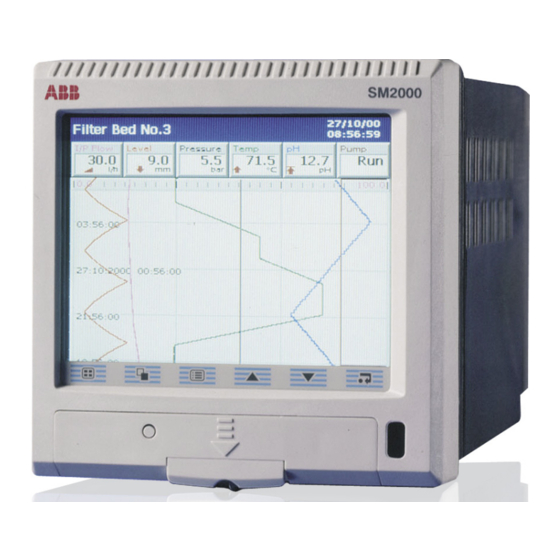
ABB SM2000 User Manual
Advanced videographic recorder
Hide thumbs
Also See for SM2000:
- User manual (111 pages) ,
- User manual supplement (25 pages) ,
- Hardware installation (12 pages)
Table of Contents
Advertisement
Quick Links
Advertisement
Table of Contents

Related Manuals for ABB SM2000


Summary of Contents for ABB SM2000
- Page 1 Advanced Videographic Recorder User Guide IM/SM2000 Issue 11 SM2000...
- Page 2 Cert. No. Q 05907 As a part of ABB, a world leader in process automation technology, we offer customers application expertise, service and support worldwide. EN 29001 (ISO 9001) We are committed to teamwork, high quality manufacturing, advanced technology and unrivalled service and support.
-
Page 3: Table Of Contents
Advanced Videographic Recorder SM2000 Contents Contents 1 INTRODUCTION .............. 3 4 CONFIGURATION ............45 Introduction ............45 4.1.1 Configuration Modes ........45 2 OPERATION ..............5 4.1.2 Configuration Level Security ....... 45 Powering up the Instrument ........5 4.1.3 Configuration Level Access ......45 Displays and Controls .......... - Page 4 Advanced Videographic Recorder SM2000 Contents 5 INSTALLATION ............100 Appendix C – Storage Capacity ........120 Siting ..............100 C.1 Internal Storage Capacity ........120 Mounting ..............101 C.2 Archive Storage Capacity ........121 Electrical Connections ..........102 Analog Inputs ............104 Appendix D – Default Settings ........123 5.4.1 Current and Voltage ........104...
-
Page 5: Introduction
Advanced Videographic Recorder SM2000 1 INTRODUCTION 1 INTRODUCTION Functional Overview – Fig. 1.1 12 Recording Channels as standard, divided into 2 Process Groups, each with 6 Recording Channels. Two Alarms and one Totalizer are assigned to each Recording Channel. Signal sources derived from universal analog inputs, the Modbus serial link, optional digital inputs or internal analog and digital signals. - Page 6 Advanced Videographic Recorder SM2000 1 INTRODUCTION Signal Sources Process Group 1 Note. Signal sources Recording can be assigned to any Channels recording channel in 1.1 to 1.6 either process group. Analog Inputs Chart View (Section 2.3) Bargraph View (Section 2.4) •...
-
Page 7: Operation
Advanced Videographic Recorder SM2000 2 OPERATION 2 OPERATION 2.1 Powering up the Instrument When power is first applied to the instrument, its processor carries out a number of self-tests and displays the start-up screen. At the end of the start-up sequence the instrument displays the Operator View that was being displayed when the instrument was powered down. - Page 8 Advanced Videographic Recorder SM2000 2 OPERATION Process Group 2 Process Group 1 (Recording Channels 2.1 to 2.6) (Recording Channels 1.1 to 1.6) Chart View Vertical Bargraph Vertical Bargraph Horizontal Bargraph Horizontal Bargraph Digital Indicator Digital Indicator Process View Process View Fig.
-
Page 9: Chart Views
Advanced Videographic Recorder SM2000 2 OPERATION 2.3 Chart Views – Fig. 2.3 Status Bar Group Tag Current Date and Time Status Icons Units Short Channel Tag Digital On/Off Tag Current Value (see Note 1 on Page 8) Channel Not Used... - Page 10 Advanced Videographic Recorder SM2000 2 OPERATION Note. 1. Current Values The Current Value, shown on the digital indicators at either the top (vertical chart view) or right hand side (horizontal chart view) of the screen, is the latest instantaneous value and its update rate is not affected by the recording sample rate.
- Page 11 Advanced Videographic Recorder SM2000 2 OPERATION Select the Configuration Level – see Section 4, page 45. Select the Setup Level – see Section 3, page 29. Note. Available only if 'Security system' is set to 'Advanced' – see Section 4.4.4, page 56.
- Page 12 Advanced Videographic Recorder SM2000 2 OPERATION Note. While in Historical Review mode: Recording of new data continues unless stopped from the Setup Menu – see Section 3.4, page 32. Invalid historical data (e.g. when recording has stopped) is denoted by '– – –' in the digital indicator.
-
Page 13: Im/Sm2000 Issue
Advanced Videographic Recorder SM2000 2 OPERATION Add one of 24 predefined Operator Messages (see Section 4.4.7, page 60) or one User- Defined Message to the alarm event log. If '< user defined >' is selected, a data entry keyboard appears to enable the message to be entered (see Fig. - Page 14 Advanced Videographic Recorder SM2000 2 OPERATION Use the 'Screen Interval' to change the amount of data displayed on the screen. A longer screen interval displays more data, a shorter screen interval displays data over a shorter time period, but in more detail. In both cases, the full trace is preserved by plotting the maximum and minimum samples for each display point.
- Page 15 Advanced Videographic Recorder SM2000 2 OPERATION Select a channel scale to be displayed in the scale bar at the top of the chart window. For digital channels, the On and Off tags are displayed at the corresponding position on the scale bar.
-
Page 16: Electronic Signatures
Advanced Videographic Recorder SM2000 2 OPERATION 2.3.1 Electronic Signatures – Fig. 2.4 Entering an electronic signature is the equivalent to signing the chart of a conventional paper recorder. Local procedures may require the approval of a record by an authorized signatory; for this reason, an electronic signature is password protected. -
Page 17: Bargraph Views
Advanced Videographic Recorder SM2000 2 OPERATION 2.4 Bargraph Views – Fig. 2.5 Status Icons Short Channel Tag Current Value Digital On or Off tag, Alarm Event Icon – according to input status see Rear fold-out Engineering Units Engineering Range High Value... - Page 18 Advanced Videographic Recorder SM2000 2 OPERATION Select the Configuration Level – see Section 4, page 45. Select the Setup Level – see Section 3, page 29. Add one of 24 predefined Operator Messages (see Section 4.4.7, page 60) or one User- Defined Message to the alarm event log.
-
Page 19: Digital Indicator View
Advanced Videographic Recorder SM2000 2 OPERATION 2.5 Digital Indicator View – Fig. 2.6 Global Alarm Status Icon Status Icons Short Channel Tag Current Value Alarm Event Icon Engineering Units Channel Units Totalizer Units Totalizer Value Opens the Operator Menu for... - Page 20 Advanced Videographic Recorder SM2000 2 OPERATION Select the Configuration Level – see Section 4, page 45. Select the Setup Level – see Section 3, page 29. Add one of 24 predefined Operator Messages (see Section 4.4.7, page 60) or one User- Defined Message to the alarm event log.
- Page 21 Advanced Videographic Recorder SM2000 2 OPERATION Stop and start individual totalizers. Channel totalizers that have not been enabled in the Configuration level are greyed-out. Note. When a totalizer is not running (i.e. 'Stop' is selected), the corresponding totalizer value is shown in red.
-
Page 22: Process View
Advanced Videographic Recorder SM2000 2 OPERATION 2.6 Process View – Fig. 2.7 Global Alarm Status Icon Alarm Trip Level Alarm Tag Alarm Acknowledged Short Channel Tag Instantaneous Value Totalizer not enabled in configuration level Alarm Status Totalizer Tag Name Totalizer... - Page 23 Advanced Videographic Recorder SM2000 2 OPERATION Select the Configuration Level – see Section 4, page 45. Select the Setup Level – see Section 3, page 29. Switch between the Alarm View and the Statistics View. Note. If a channel's totalizer is not enabled in the Configuration level, Alarm trip levels are shown in place of the channel statistics.
- Page 24 Advanced Videographic Recorder SM2000 2 OPERATION Reset the totalizer value to the totalizer preset value. Channel totalizers that have not been enabled in the Configuration level are greyed-out. To acknowledge a particular alarm, use the keys to highlight it in the menu and press the key.
-
Page 25: Alarm Event Log
Advanced Videographic Recorder SM2000 2 OPERATION 2.7 Alarm Event Log – Fig. 2.8 Note. The Alarm Event log view provides an historical log of all alarm events in the sequence in which they occurred. To view the current status of all alarms, choose the Process View – see Section 2.6, page 20. - Page 26 Advanced Videographic Recorder SM2000 2 OPERATION Select the Configuration Level – see Section 4, page 45. Select the Setup Level – see Section 3, page 29. Select the entries to be displayed in the log. Indicates entries currently displayed.
-
Page 27: Totalizer Log
Advanced Videographic Recorder SM2000 2 OPERATION 2.8 Totalizer Log – Fig. 2.9 Note. The Totalizer log view provides an historical log of totalizer activity. To view the current totalizer status, choose the Process or Digital View. When the number of entries in the Totalizer log has reached that defined in 'Totalizer log size' (see Section 4.4.6, page 60), the oldest data is overwritten by the newest. - Page 28 Advanced Videographic Recorder SM2000 2 OPERATION Select the Configuration Level – see Section 4, page 45. Select the Setup Level – see Section 3, page 29. Select the entries to be displayed in the log. Indicates entries currently displayed. This does not affect which events are recorded in the log.
-
Page 29: Audit Log
Advanced Videographic Recorder SM2000 2 OPERATION 2.9 Audit Log– Fig. 2.10 Note. The Audit log view provides an historical log of system activity. When the number of entries in the Audit log has reached that defined in 'Audit log size' (see Section 4.4.6, page 60), the oldest data is overwritten by the newest. -
Page 30: Status View
Advanced Videographic Recorder SM2000 2 OPERATION 2.10 Status View – Fig. 2.11 Note. The Status view provides an overview of the instrument's status. Cold junction temperatures Instrument Software Version for Modules A & B; measured by the built-in cold junction Operating System Version circuitry. -
Page 31: Setup
Advanced Videographic Recorder SM2000 3 SETUP 3 SETUP 3.1 Introduction Note. Users with Setup access can: Start/Stop recording. Switch between primary and secondary recording rates. Set archiving 'on-line' and 'off-line'. View internal and external archive media file directories and delete external archive media files. - Page 32 Advanced Videographic Recorder SM2000 3 SETUP Note. Do not use sharp objects such as screwdrivers, pen nibs etc. to operate the touch screen. Note. The Setup level can be Invalid Password Entered accessed from any operator screen. (see Note Below)
-
Page 33: Password Entry
Advanced Videographic Recorder SM2000 3 SETUP 3.3 Password Entry Enter Password Enter the required password using the touchscreen and press 'OK'. Note. For security, all characters are displayed as ''. Change Password 1. Press the 'Change' button. 2. Enter the old password. -
Page 34: Setup Menu
Advanced Videographic Recorder SM2000 3 SETUP 3.4 Setup Menu Use this menu to stop and start recording or switch between the Primary and Secondary sample rates on one or more channels in the current Process Group. The Primary sample rate is set typically to a relatively slow rate (depending upon process recording requirements) and is active during normal process operating conditions in order to maximize internal memory and external archive media. - Page 35 Advanced Videographic Recorder SM2000 3 SETUP Places the archive media on-line, starting the archiving process. Note. The On-line function is disabled (greyed-out in the Setup Menu) if no archive media card is inserted or the instrument has been placed in Historical Review mode.
-
Page 36: Archiving
Advanced Videographic Recorder SM2000 3 SETUP 3.5 Archiving Recorded data, logs and configuration files stored on the instrument's internal memory can be archived to files created on removable media. Parameters for archiving Process Groups 1 and 2 data are set up independently. -
Page 37: Inserting And Removing Media
Advanced Videographic Recorder SM2000 3 SETUP 3.5.3 Inserting and Removing Media – Fig. 3.4 Set the archive media off-line – see Section 3.4, page 33 Withdraw the media Press the eject button Compact Flash Media SmartMedia Unlock the media door with Note. -
Page 38: Archive File Types
Advanced Videographic Recorder SM2000 3 SETUP 3.5.4 Archive File Types Archive files are created in one of two user-selectable formats: No. of Type Extension Contents Files Text (comma separated values [.csv]) – see Section 3.6, Channel One per Analog or digital recording page 37 *.B00... -
Page 39: Text Format Archive Files
Advanced Videographic Recorder SM2000 3 SETUP 3.6 Text Format Archive Files 3.6.1 Text Format Channel Data Files Text format channel data files can be configured to contain data Files containing data generated during the daylight saving period gathered over a predefined period of time using the 'New File (summertime) have '~DS' appended to the filename. -
Page 40: Text Format Filename Examples
Advanced Videographic Recorder SM2000 3 SETUP 3.6.2 Text Format Filename Examples 3.6.3 Text Format Log files 'New file interval' set to 'Hourly', 'Filename tag' set to 'Process The Alarm Event and Totalizer Logs for each Process Group and Group 1' (see Section 4.5.6, page 73); date is 10th October the Audit Log are archived into individual files. -
Page 41: Text Format Data File Examples
Advanced Videographic Recorder SM2000 3 SETUP 3.6.4 Text Format Data File Examples – Figs. 3.5 to 3.8 3.6.5 Text Format Data File Digital Signatures – Fig. 3.5 Text format archived data is stored in a comma separated value A digital signature file is created for each channel data file using (*.csv) format so that it can be imported directly into a standard... - Page 42 Advanced Videographic Recorder SM2000 3 SETUP Fig. 3.7 Totalizer Log Sample – Text Format Fig. 3.8 Audit Log Sample – Text Format IM/SM2000 Issue 11...
-
Page 43: Binary Format Archive Files
Advanced Videographic Recorder SM2000 3 SETUP 3.7 Binary Format Archive Files Example 2 – End of daylight saving period: Archiving is started at 00:15:00 on 26th October 2003 – 3.7.1 Binary Format Archive Filenames filename: 00150026Oct03Ch1_1AnlgSM2000~DS.B00. Examples of binary archive filenames are shown in Table 3.5. - Page 44 Advanced Videographic Recorder SM2000 3 SETUP Fig. 3.9 Channel Data File Sample – Binary Format Fig. 3.10 Alarm Event Log Sample – Binary Format IM/SM2000 Issue 11...
- Page 45 Advanced Videographic Recorder SM2000 3 SETUP Fig. 3.11 Totalizer Log Sample – Binary Format Fig. 3.12 Audit Log Sample – Binary Format IM/SM2000 Issue 11...
-
Page 46: Archiving Online/Offline
Advanced Videographic Recorder SM2000 3 SETUP 3.8 Archiving Online/Offline External archive media can be set on-line (if a media card Before data can be archived to external media, the external is inserted) or off-line in the setup menu. media must be placed on-line and one or more archive file Set archiving off-line before removing external media to enables set. -
Page 47: Configuration
Advanced Videographic Recorder SM2000 4 CONFIGURATION 4 CONFIGURATION The instrument can be configured for one of two levels of password protection: 4.1 Introduction Basic Security: This section details the configuration of the instrument locally Up to 4 users using the touch screen. A configuration file can also be created... - Page 48 Advanced Videographic Recorder SM2000 4 CONFIGURATION Note. Do not use sharp objects such as screwdrivers, pen nibs etc. to operate the touch screen. Invalid Password Entered Displayed only if 'Security system' parameter is set to Displayed only if 'Security 'Basic' –...
- Page 49 Advanced Videographic Recorder SM2000 4 CONFIGURATION Note. The Internal Security Switch is used to access the Configuration level when 'Configuration security type' is set to 'Internal switch protected' – see Section 4.4.4, page 56. use the switch to access the Configuration level when 'Configuration Do Not security type' is set to 'Password protected' (default setting) unless the Password has been forgotten.
-
Page 50: Overview Of Configuration
Advanced Videographic Recorder SM2000 4 CONFIGURATION 4.2 Overview of Configuration – Fig. 4.3 Select the Common Configuration icon in the main configuration window (see below). Note 1 Close the Configuration Window and Save or Cancel the changes (see below) Note 2... -
Page 51: Making Changes To Parameters
Advanced Videographic Recorder SM2000 4 CONFIGURATION 4.3 Making Changes to Parameters – Figs. 4.4 to 4.6 Channel Selectors (Recording Channel configuration only) Edit Button Configuration Tab Parameter Parameter Value Sub-menu Note. The appropriate data entry box is displayed automatically – see Fig. 4.5... - Page 52 Advanced Videographic Recorder SM2000 4 CONFIGURATION Parameter Limits Tick Box Numeric Keypad List Box Note. Items not selected are indicated Note. Values outside the preset by an X in the parameter window. parameter limits or with too many decimal places are highlighted.
- Page 53 Selecting 'Save as Current Configuration' suspends recording for a short time while the new configuration is implemented. When saving the current configuration to internal storage, the file is saved automatically with the 'SM2000.cfg' filename, and with a '<time><date><instrument tag>.cfg' filename.
-
Page 54: Common Configuration
Advanced Videographic Recorder SM2000 4 CONFIGURATION 4.4 Common Configuration Fig. 4.7 Selecting Common Configuration 4.4.1 Setup Select the Configuration type required – see Section 4.1.1, page 45. Note. Parameters applying only to Advanced or to Basic Configuration are identified respectively. -
Page 55: Screen
Advanced Videographic Recorder SM2000 4 CONFIGURATION 4.4.2 Screen Select the waiting time between the last key press and activation of the screen saver. When set to 'Enabled', the user can save an image of any Operator screen to external archive media by pressing the key when an Operator Menu is not open. -
Page 56: Time
Advanced Videographic Recorder SM2000 4 CONFIGURATION 4.4.3 Time Set the current date and time. Note. If daylight saving is required, enter the settings (see next page) setting the time and date as the operation of the before internal clock is affected by the daylight saving settings. - Page 57 Advanced Videographic Recorder SM2000 4 CONFIGURATION Select the daylight saving method. Note. Changes to daylight saving are effective immediately a method is selected. However, if 'Cancel' is selected upon exiting Configuration Mode (see Fig. 4.6, page 51), the last saved daylight saving settings are restored.
-
Page 58: Security
Advanced Videographic Recorder SM2000 4 CONFIGURATION 4.4.4 Security Note. User 1 is the System Administrator and is able to change the Security type and all other security parameters. Other users can change only the 'Setup level security' setting and only if 'Security system' is set to 'Basic'. - Page 59 Advanced Videographic Recorder SM2000 4 CONFIGURATION Note. The following parameters: are displayed only if 'Security system' is set to 'Advanced' – see page 56. can be changed only by the System Administrator (User 1). Passwords are entered initially by the System Administrator but, subsequently, any user can change their own password.
-
Page 60: Users
Advanced Videographic Recorder SM2000 4 CONFIGURATION 4.4.5 Users Note. User 1 is the System Administrator and is able to change user names/access privileges and enter initial passwords for all other users. Other users cannot change their user names and access privileges once set by User 1. All users may change their own passwords. - Page 61 Advanced Videographic Recorder SM2000 4 CONFIGURATION Note. The following parameters are displayed only if 'Security system' is set to 'Advanced' – see Section 4.4.4, page 56. Configure User 1 (System Administrator) Note. Full Configuration level access privileges for User 1 cannot be disabled but Setup level access and the Electronic Signature privilege may be enabled/disabled as required.
-
Page 62: Logs
Advanced Videographic Recorder SM2000 4 CONFIGURATION 4.4.6 Logs Set the maximum number of entries in each instrument log. Note. Changing the log size deletes the current log entries. records all process alarm transitions Alarm Event log (inactive to active, unacknowledged to acknowledged or active to inactive), real-time events and Operator Messages –... -
Page 63: Rs485 (Modbus™) Communications
Advanced Videographic Recorder SM2000 4 CONFIGURATION 4.4.8 RS485 (Modbus™) Communications Refer to Appendix B, page 110 for further information on using the Modbus link. Select the Modbus protocol required. Modbus – instrument acts as a Modbus Slave Modbus Master – instrument acts as a Modbus Master Set according to the number of transmission wires connected to the instrument: 4-wire, 2-wire. -
Page 64: Comms Analog Input
Advanced Videographic Recorder SM2000 4 CONFIGURATION 4.4.9 Comms Analog Input Note. This tab is displayed only if 'Protocol' is set to 'Modbus Master' – see Section 4.4.8, page 61. Select the comms analog input to hold the data from the nominated slave device. -
Page 65: Comms Digital Input
Advanced Videographic Recorder SM2000 4 CONFIGURATION 4.4.10 Comms Digital Input Note. This tab is displayed only if 'Protocol' is set to 'Modbus Master' – see Section 4.4.8, page 61. Select the comms digital input to hold the data from the nominated slave device. -
Page 66: Process Group Configuration
Advanced Videographic Recorder SM2000 4 CONFIGURATION 4.5 Process Group Configuration Process Group 1 Process Group 2 Fig. 4.8 Selecting Process Group Configuration Note. If 'Number of groups' is set to '1' (see Section 4.4.1, page 52), only one Process Group icon and associated Channels icon is displayed in the main configuration window. - Page 67 Advanced Videographic Recorder SM2000 4 CONFIGURATION When 'Configuration type' is set to 'Basic' (see Section 4.4.1, page 52), the instrument can be configured to sample all recording channels in the group simultaneously and store the data in internal memory and external archive media (if archiving is enabled) at two rates, Primary and Secondary.
- Page 68 Advanced Videographic Recorder SM2000 4 CONFIGURATION Set the Secondary sample rate to between 0.1 seconds and 720 minutes (12 hours). •1 Select a signal source to enable switching between the primary and secondary sample rates. Refer to Appendix A, page 108 for •1...
-
Page 69: Configuring The Chart View
Advanced Videographic Recorder SM2000 4 CONFIGURATION 4.5.2 Configuring the Chart View Major Chart Divisions Minor Chart Divisions Scale Bar Chart Trace Time Stamp Screen Interval Operator Message Annotation Alarm Event Annotation Chart Divisions Vertical Chart Screen Interval Horizontal --> Chart Horizontal <-- Chart... - Page 70 Advanced Videographic Recorder SM2000 4 CONFIGURATION Select Horizontal --> (Chart runs left to right with scale bar on left), Horizontal <--(chart runs right to left with scale bar on right), or Vertical chart view. Select the annotations to be displayed on the chart. Alarm events and operator messages are displayed on the chart adjacent to the point at which the alarm occurred –...
- Page 71 Advanced Videographic Recorder SM2000 4 CONFIGURATION Enable trace pointers to display a chart scale bar with pointers to indicate the instantaneous trace positions. Disable trace pointers to display the standard chart scale bar. Select the amount of historical data to be displayed on the screen.
-
Page 72: Configuring The Bargraph View
Advanced Videographic Recorder SM2000 4 CONFIGURATION 4.5.3 Configuring the Bargraph View Alarm Trip Level Engineering High Value (not shown for slow and fast rate alarms) Maximum Value Engineering Middle Value (solid color) Instantaneous Value Minimum Value (white fill) Engineering Low Value... -
Page 73: Configuring The Process View
Advanced Videographic Recorder SM2000 4 CONFIGURATION 4.5.4 Configuring the Process View Alarms View – Totalizer Enabled Totalizer Tag Name Alarm Acknowledged Totalizer Value Alarm Tag Alarm Trip Level Statistics View – Totalizer Enabled Channel Long Tag Name Average Values since last Totalizer Reset or Totalizer wrap. -
Page 74: Configuring The Digital Indicator View
Advanced Videographic Recorder SM2000 4 CONFIGURATION 4.5.5 Configuring the Digital Indicator View Short Channel Tag Current Value Alarm Status Units Channel Units Totalizer Units See Note below Totalizer Value Note. Displayed only if the totalizer is enabled for that channel (see Section 4.6.5, page 90) and for display (see below). -
Page 75: Archiving
Advanced Videographic Recorder SM2000 4 CONFIGURATION 4.5.6 Archiving Introduction Recorded data, logs and configuration files stored in the instrument's internal memory can be archived to files created in removable media in either text or binary encoded format. Parameters for archiving Process Group 1 are set up independently from Process Group 2 parameters. - Page 76 Advanced Videographic Recorder SM2000 4 CONFIGURATION Select the archive file format required – Text format or Binary format. Notes. Parameters applying only to Advanced or to Basic Configuration are identified respectively. The selected archive file format is applied automatically to process groups.
- Page 77 Advanced Videographic Recorder SM2000 4 CONFIGURATION Note. Displayed only if 'Archive file format' (above) is set to 'Text format'. Enter the filename (max. 20 characters) to be used to identify the channel data archive files. Note. The following characters cannot be used in the filename tag: \, /, :, *, ?, ", <, >, |, superscript characters, ~, Ω...
-
Page 78: Channel Configuration
Advanced Videographic Recorder SM2000 4 CONFIGURATION 4.6 Channel Configuration Process Group 1, Process Group 2, Channels 1.1 to 1.6 Channels 2.1 to 2.6 Fig. 4.10 Recording Channel Configuration Oldest Un-archived Data Archive Triggers <1 Day Old (Binary) or <1 Hour Old (Text) >1 Day Old (Binary) or >1 Hour Old (Text) -
Page 79: Recording Channel Setup
Advanced Videographic Recorder SM2000 4 CONFIGURATION 4.6.1 Recording Channel Setup Note. Parameters applying only to Advanced configuration are identified Select the signal source for the selected channel. This can be any external analog or digital signal – see Appendix A, page 108 •1... - Page 80 Advanced Videographic Recorder SM2000 4 CONFIGURATION Select the filter to be applied to the electrical input prior to •1 sampling. Notes. Applicable to analog sources only. Filters are applied to the recorded values shown on the chart view only, not to instantaneous values displayed on the channel indicators or bargraphs.
- Page 81 Advanced Videographic Recorder SM2000 4 CONFIGURATION When 'Configuration type' is set to 'Advanced' (see Section 4.4.1, page 52), the instrument can be configured to sample each recording channel individually and store the data in internal memory and external archive media (if archiving is enabled) at two rates, Primary and Secondary.
-
Page 82: Analog Input Configuration
Advanced Videographic Recorder SM2000 4 CONFIGURATION •1 If this parameter is changed, internally recorded data files are recreated and unarchived data is lost. 4.6.2 Analog Input Configuration Note. The 'Analog I/P' tab is displayed only if 'Source ID' for the Recording Channel is set to an analog signal source – see Section 4.6.1, page 77. - Page 83 Advanced Videographic Recorder SM2000 4 CONFIGURATION Set the required electrical range. Notes. Applicable only to mA, mV, V and Resistance input types. When an input is connected through an external voltage divider (see on page 80), set the electrical range...
- Page 84 Advanced Videographic Recorder SM2000 4 CONFIGURATION Enter the tag name to be displayed on channel indicators and •1 used to identify the channel in archive files (8 characters max.). Note. Tags with a high percentage of capital letters and wide characters such as 'W' or 'M' may appear truncated in some Operator Views.
-
Page 85: Digital Input Configuration
Advanced Videographic Recorder SM2000 4 CONFIGURATION 4.6.3 Digital Input Configuration Note. The 'Digital I/P' tab is displayed only if 'Source ID' for the Recording Channel is set to a digital signal source – see Section 4.6.1, page 77. •1 Note. This parameter is displayed only if 'Input type' on the 'Analog I/P' tab is set to 'Volt free digital input'. -
Page 86: Alarm Configuration
Advanced Videographic Recorder SM2000 4 CONFIGURATION 4.6.4 Alarm Configuration Hysteresis Trip Point Hysteresis Process Variable Alarm On High Process Alarm Off Alarm On Low Process Alarm Off Fig. 4.11 High/Low Process Alarms Trip Point Hysteresis Process Variable Alarm On Alarm Latched... - Page 87 Advanced Videographic Recorder SM2000 4 CONFIGURATION Process Variable Trip Point Hysteresis Hysteresis Trip Point Process Variable Alarm On Alarm On Alarm Off Alarm Off Alarm acknowledged Alarm acknowledged by operator by operator High Annunciate Alarm Action Low Annunciate Alarm Action Fig.
- Page 88 Advanced Videographic Recorder SM2000 4 CONFIGURATION Process variable goes Process variable goes Process variable goes above trip point but above trip point but Process variable goes above trip point, alarm is alarm is not activated alarm is not activated below trip (hysteresis)
- Page 89 Advanced Videographic Recorder SM2000 4 CONFIGURATION Note. The Alarm Configuration tabs are displayed only if 'Source ID' for the Recording Channel is set to an analog signal source – see Section 4.6.1, page 77. Set the alarm type: High/Low process –...
- Page 90 Advanced Videographic Recorder SM2000 4 CONFIGURATION Note. Delayed process alarms only – see Fig. 4.15. Set the value, in engineering units, at which the alarm is to activate. Set the hysteresis value in engineering units and the delay time in seconds.
- Page 91 Advanced Videographic Recorder SM2000 4 CONFIGURATION Select an alarm Enable source. When the 'Enable source' is active, the alarm is enabled. When the source is inactive the alarm is disabled. If set to 'None' the alarm is always enabled. Note. For Delayed Process alarm operation, see Fig. 4.15, page 86.
-
Page 92: Totalizer Configuration
Advanced Videographic Recorder SM2000 4 CONFIGURATION 4.6.5 Totalizer Configuration Note. Current totalizer values are displayed in the Digital Indicator and Process Views – see Sections 2.5 and 2.6 (Operation), and Sections 4.5.5 and 4.5.4 (Configuration) respectively. For analog sources, the total value of a signal is calculated by counting pulses produced at a rate proportional to the input. - Page 93 Advanced Videographic Recorder SM2000 4 CONFIGURATION Set the 'Preset count' value – the value the totalizer counts from and the value applied when the totalizer is reset. Set the 'Predetermined count' value – the value at which the totalizer stops or wraps.
- Page 94 Advanced Videographic Recorder SM2000 4 CONFIGURATION Set the required totalizer count rate and cut off value. The count rate is determined by the maximum number of engineering units (or pulses) per second and the smallest Analog Input Sources only – see Section 4.6.1, page 77.
-
Page 95: Scales
Advanced Videographic Recorder SM2000 4 CONFIGURATION 4.6.6 Scales Note. Parameters applying only to Advanced configuration are identified The scales configured here are used to scale analog channel data in the Chart View when 'Configuration type' is set to 'Advanced' – see Section 4.4.1, page 52. It has no effect on the Bargraph View (which always uses the engineering range of the analog signal displayed –... -
Page 96: I/O Module Configuration
Advanced Videographic Recorder SM2000 4 CONFIGURATION 4.7 I/O Module Configuration Modules Fig. 4.16 I/O Module Configuration Note. The instrument detects the type of module fitted in each position automatically. 4.7.1 Analog Inputs Set the mains rejection frequency used to electrical noise induced on the signal lines by power supply cables. -
Page 97: Relay Modules
Advanced Videographic Recorder SM2000 4 CONFIGURATION Offset adjust / Span adjust Manually fine-tune the offset adjust and span adjust values to remove process errors. These are calculated values applied to the raw input signal. Note. If simulating thermocouple inputs, connect the millivolt... -
Page 98: Hybrid Modules
Advanced Videographic Recorder SM2000 4 CONFIGURATION 4.7.3 Hybrid Modules Select a digital output source. Note. A digital output source is the internal digital source used to activate/de-activate a digital output. If a digital output is used to provide a totalizer count pulse, the maximum pulse frequency is 5Hz. -
Page 99: Ethernet Modules
Advanced Videographic Recorder SM2000 4 CONFIGURATION Select the analog output source. Note. The analog output source can be any internal or external analog signal. Set the required analog output engineering and electrical ranges. Note. The 'Engineering low' and 'Engineering high' settings are the engineering values corresponding to the 'Electrical low' and 'Electrical high' values below. -
Page 100: Functions
Advanced Videographic Recorder SM2000 4 CONFIGURATION 4.9 Functions Functions Fig. 4.17 Functions Configuration 4.9.1 Custom Linearizers Press the key adjacent to the linearizer to be adjusted to open the Adjust custom linearizer' window. Use the keys to highlight the point to be modified. -
Page 101: Real-Time Alarms
Advanced Videographic Recorder SM2000 4 CONFIGURATION 4.9.2 Real-time Alarms Enter the tag to be used in the Alarm Event log – see Section 2.7, page 23. Set the day(s) on which the alarm is activated. Set to 'On' to activate the real-time alarm on the first day of each month. -
Page 102: Installation
Advanced Videographic Recorder SM2000 5 INSTALLATION 5 INSTALLATION 50°C (122°F) EC Directive 89/336/EEC Max. 0°C In order to meet the requirements of EC Directive 89/336/ (32°F) EEC for EMC regulations, this product must not be used in Min. a non-industrial environment. -
Page 103: Mounting
Advanced Videographic Recorder SM2000 5 INSTALLATION 5.2 Mounting – Figs. 5.3 and 5.4 Dimensions in mm (in.) AC Power Supply Gasket (0.27) 155.0 (6.1) 40 (1.57) Earth (Ground) Stud +1.0 –0.0 144.0 Panel Cut-out (5.67) +0.04 (5.43 –0.0 +1.0 –0.0 144.0 (5.67) -
Page 104: Electrical Connections
Advanced Videographic Recorder SM2000 5 INSTALLATION 5.3 Electrical Connections – Fig. 5.5 Warning. The instrument is not fitted with a switch therefore a disconnecting device such as a switch or circuit breaker conforming to local safety standards must be fitted to the final installation. It must be fitted in close proximity to the instrument within easy reach of the operator and must be marked clearly as the disconnection device for the instrument. - Page 105 Advanced Videographic Recorder SM2000 5 INSTALLATION Module Positions External Voltage Divider – see Warning on page 104. AC Power Supply Earth (Ground) Stud – see Warning on page 102 – Positions A and B Positions B, Positions B, Position C...
-
Page 106: Analog Inputs
Advanced Videographic Recorder SM2000 5 INSTALLATION 5.4 Analog Inputs 5.4.1 Current and Voltage – Fig. 5.6 – – – Warning. 10W Resistor supplied When input 'Type' is set to 'Volts' (see Section 4.6.2, Voltage divider in accessory pack. (GR2000/0375) page 80), input signals with voltages greater than 2V... -
Page 107: Rs422/485 Serial Communications
Advanced Videographic Recorder SM2000 5 INSTALLATION 5.5 RS422/485 Serial Communications The serial interface fitted to this instrument has been designed Host Computer to operate using the Modbus Remote Terminal Unit (RTU) Master/Slave protocol. An appropriate RS422/485 communications driver must be Module Position F fitted to the host (Master) computer. -
Page 108: Mains Power Connections
Advanced Videographic Recorder SM2000 5 INSTALLATION Compensating Cable BS1843 ANSI MC 96.1 DIN 43714 BS4937 Part No.30 Type of Thermocouple – Case – Case – Case – Case Ni-Cr/Ni-Al (K) Brown Blue Yellow Yellow Green Green Green White Green Ni-Cr/Cu-Ni (E) —... -
Page 109: Hybrid I/O Module Connections
Advanced Videographic Recorder SM2000 5 INSTALLATION 5.8 Hybrid I/O Module Connections 5.8.2 Digital Input Connections – Fig. 5.13 Six digital inputs are provided on Hybrid option boards. 5.8.1 Digital Output Connections – Fig. 5.12 Six digital outputs are provided on the Hybrid option board. -
Page 110: Appendix A - Signal Sources
Advanced Videographic Recorder SM2000 Appendix A – Signal Sources Appendix A – Signal Sources Source Name Description Analog Sources Analog I/P A1 Analog input values (from Analog input module). Available only if an analog input module is fitted in the relevant position. - Page 111 Advanced Videographic Recorder SM2000 Appendix A – Signal Sources Source Name Description Comms Dig I/P 1 Digital Input States. Received via the Modbus/Modbus TCP serial communications link – see Appendix B, page 110. Comms Dig I/P 24 Alarm state 1.1A Alarm States.
-
Page 112: Appendix B - Modbus Guide
Advanced Videographic Recorder SM2000 Appendix B – Modbus Guide Appendix B – Modbus Guide Note. B.1 Introduction Negative numbers are represented in '2's This instrument is fitted with a Modbus/RS485 serial complement' format, e.g 1000 = 03E8 (Hex), -1000 = communications link as standard. - Page 113 Advanced Videographic Recorder SM2000 Appendix B – Modbus Guide Alarm Alarm Acknowledge Coil Number Active/Inactive Read: Always returns '0' Read Access 0 = Alarm inactive 0 = Acknowledged or Title Write: 1 = Activate 1 = Alarm active inactive Operator Message 1...
- Page 114 Advanced Videographic Recorder SM2000 Appendix B – Modbus Guide Title Coil Number Read Write Assign to Group 1 0181 Remote operator message not assigned to group Unassign remote operator message from group Remote operator message assigned to group Assign remote operator message to group...
- Page 115 Advanced Videographic Recorder SM2000 Appendix B – Modbus Guide Modbus Registers Stop/Go Reset Wrap Pulse 1st Stage Pulse Flowrate Failure Read 0 = Stopped 0 = >1s* 0 = Inactive 0 = Inactive 0 = OK 1 = Running 1 = <1s*...
- Page 116 Advanced Videographic Recorder SM2000 Appendix B – Modbus Guide Modbus Coil Read Only. 0 = All alarms inactive Title Read Only. 0 = OK, 1 = Failed 1 = At least 1 alarm active Math Block 1 Failure 0681 Title...
- Page 117 Advanced Videographic Recorder SM2000 Appendix B – Modbus Guide Read Only: 0 = All alarms inactive 1 = At least 1 alarm active Coil Coil Coil Coil Title Title Title Title Number Number Number Number BCD digital I/P D0 0801...
-
Page 118: Operating Mode Modbus Registers
Advanced Videographic Recorder SM2000 Appendix B – Modbus Guide B.6 Operating Mode Modbus Registers Trip Point Registers Tables B.15 to B.21 detail the contents of the Modbus registers (single precision floating point) accessible while the instrument is in the operating mode. - Page 119 Advanced Videographic Recorder SM2000 Appendix B – Modbus Guide Modbus Registers Current Batch Previous Batch Maximum Minimum Average Maximum Minimum Average Batch Total Batch Total Flowrate Flowrate Flowrate Flowrate Flowrate Flowrate Read only, Read only, double Read only, single precision floating...
-
Page 120: Comms. Analog And Digital Inputs
Advanced Videographic Recorder SM2000 Appendix B – Modbus Guide B.7 Comms. Analog and Digital Inputs Comms. Comms. Analog Comms. Analog Comms. Comms. Analog Comms. Analog Digital Inputs Inputs Failure Inputs Digital Inputs Inputs Failure Inputs Read/Write: Read/Write: Floating point Floating point (–999 to 9999) - Page 121 Advanced Videographic Recorder SM2000 Appendix B – Modbus Guide Char Char Char Char Char Space “ & < > Char £ ° ² ³ µ Ω Note. Character codes 2C, 60 and 7F Hex (44, 96 and 127 Dec) are not supported Table B.21 ASCII Character Set for Remote Operator Messages...
-
Page 122: Appendix C - Storage Capacity
Advanced Videographic Recorder SM2000 Appendix C – Storage Capacity Appendix C – Storage Capacity C.1 Internal Storage Capacity Number of Channels Sample Rate 0.1 seconds 27.3 hours 13.7 hours 9.1 hours 6.8 hours 0.2 seconds 2.3 days 1.1 days 18.2 hours 13.7 hours... -
Page 123: Archive Storage Capacity
Advanced Videographic Recorder SM2000 Appendix C – Storage Capacity C.2 Archive Storage Capacity Note. The storage capacity times shown are for archiving of a single group. If two groups are archived, the durations are halved. Media Size Sample Rate 128 Mb... - Page 124 Advanced Videographic Recorder SM2000 Appendix C – Storage Capacity Media Size Sample Rate 128 Mb 256 Mb 512 Mb 1 Gb 0.1 seconds 1.7 weeks 3.5 weeks 1.6 months 3.2 months 0.2 seconds 3.5 weeks 1.6 months 3.2 months 6.3 months 0.3 seconds...
-
Page 125: Appendix D - Default Settings
Advanced Videographic Recorder SM2000 Appendix D – Default Settings Appendix D – Default Settings D.1.2 Process Groups 1 to 6 Recording D.1 Company Standard Group 1 tag Process Group 1 Group 2 tag Process Group 2 D.1.1 Common Configuration Recording enable source... -
Page 126: Recording Channels
Advanced Videographic Recorder SM2000 Appendix D – Default Settings D.1.3 Recording Channels Setup Totalizers Source indentifiers Count enable Channels 1.1 to 1.6 Analog input A1 to A6 Wrap enable Channels 2.1 to 2.6 Analog input B1 to B6 Channel x.x totalizer tag Total flow x.x... -
Page 127: Functions
Advanced Videographic Recorder SM2000 Appendix D – Default Settings D.1.5 Functions D.2.2 QSFlow Custom Linearizers 1 and 2 As D.2.1 QSMilliAmp, except: X co-ordinates 0.0, 5.0, 10.0, 15.0, 20.0, Analog Inputs (A1 to A6 and B1 to B6) 25.0, 30.0, 35.0, 40.0, Engineering range 45.0, 50.0, 55.0, 60.0,... -
Page 128: Qsdemo
Advanced Videographic Recorder SM2000 Appendix D – Default Settings D.2.7 QSDEMO As D.1 Company Standard except: Alarm State 1.1A (Digital Recording Channel 1.6) Screen Digital on tag Open Screen Capture Enabled Digital off tag Close Operator messages Short tag Valve... -
Page 129: Qsdairy
Advanced Videographic Recorder SM2000 Appendix D – Default Settings D.2.8 QSDAIRY As D.2.5 QSRTD_C except: Ch1.1 Alarm A Recording Alarm type Delayed high process Primary sample rate 1 min Trip 10.0 °C Chart View Hysteresis/Delay time Screen interval 2 days/screen Hysteresis 0.5 °C... -
Page 130: Appendix E - Spare Parts And Accessories
Advanced Videographic Recorder SM2000 Appendix E – Spare Parts and Accessories Appendix E – Spare Parts and Accessories Media Door Keys GR2000/0725 Panel Clamp GR2000/0723 Voltage Divider Board GR2000/0375 (inc. 250Ω shunt GR2000/0377) Compact Flash Card 512Mb B12156 B12567 B12568... - Page 131 Advanced Videographic Recorder SM2000 Appendix E – Spare Parts and Accessories 20-way Terminal Block for analog input modules: GR2000/0726 for other modules: GR2000/0727 8-way Terminal Block GR2000/0728 Instrument to Panel Seal PR100/0186 Terminal Compartment GR2000/0716 Removable Media Options (in place of existing option, if fitted)
-
Page 132: Appendix F - Error & Diagnostics Information
If the error persists, try another card. The unit runs slowly and the red archive arrow is on continually, even If a very large number of files (>500) exist in the SM2000 directory on when there is apparently no unarchived data to catch-up the removable media card, some delay may be experienced during archiving. -
Page 133: Appendix G - Symbols And Icons
Advanced Videographic Recorder SM2000 Appendix G – Symbols and Icons Appendix G – Symbols and Icons Process Group Name Status Icons Process Group 1 Configuration Historical Review Active Process Group 2 Configuration External archive media on-line (green icon, shaded area indicates % used) Channel 1.1 to 1.6 Configuration... -
Page 134: Index
Advanced Videographic Recorder SM2000 Index Index Accessories ...............3 Channel Indicator Advanced Configuration ........10, 12, 13 Tags ..............82, 83 Advanced Security – See Security System: Advanced Chart Alarm Event Log ............23, 24 Annotation ............11, 68 Filter ................24 AutoView Scroll ........13, 16, 19, 22 Size ................60... - Page 135 Advanced Videographic Recorder SM2000 Index Date and Time ............54 to 55 Language ............... 52 Daylight Saving ..........10, 41, 55 Linearizer Type ............... 80 Diagnostics (Math and Logic) – See also Advanced Linearizer Units ............... 80 Software Options User Guide Supplement, IM/SM2000ADV Log Sizes ...............
- Page 136 Advanced Videographic Recorder SM2000 Index Passwords Thermocouple Compensating Cable ..... 95, 104, 106 Entering ..............31 Totalizer Log ............25 to 26 Configuration ............. 60 Entry Failure Limit ............57 Filter ................26 Expiry ..............31, 57 Update Frequency ............. 91 Length ...............57 Totalizers Primary and Secondary Sample Rates .....12, 29,...
- Page 137 – Chemical & Pharmaceutical details on your nearest Service and Repair Centre. – Food & Beverage United Kingdom – Manufacturing ABB Limited – Metals and Minerals Tel: +44 (0)1480 475321 – Oil, Gas & Petrochemical Fax: +44 (0)1480 217948 –...
- Page 138 Modbus™ is a registered trademark of the Modbus-IDA organization Microsoft is a registered trademark of Microsoft Corporation in the United States and/or other countries ABB has Sales & Customer Support expertise The Company's policy is one of continuous product in over 100 countries worldwide improvement and the right is reserved to modify the information contained herein without notice.