ABB COM600 series User Manual
Substation management unit
Hide thumbs
Also See for COM600 series:
- Data historian operator's manual (140 pages) ,
- User manual (104 pages) ,
- Configuration manual (66 pages)
Table of Contents
Advertisement
Quick Links
Advertisement
Table of Contents

Related Manuals for ABB COM600 series


Summary of Contents for ABB COM600 series
- Page 1 COM600 series, version 4.1 User's Manual...
-
Page 3: Table Of Contents
Abbreviations ................11 1.10. Related documents ..............12 1.11. Document revisions ..............13 Introduction ................... 14 2.1. General about the COM600 series ..........14 2.2. COM600 series products and rationale ........14 2.3. Overview of COM600 ..............15 Features ....................16 3.1. - Page 4 COM600 series, version 4.1 1MRS756125 User's Manual Installation ..................... 39 5.1. About this section ................. 39 5.2. Requirements for SAB600 ............39 5.3. Installing SAB600 ................. 39 5.4. Updating SAB600 ................ 40 5.5. Setting up the COM600 computer ..........41 5.5.1.
- Page 5 1MRS756125 COM600 series, version 4.1 User's Manual Operation ....................90 7.1. Activating COM600 with new configurations ....... 90 7.2. License handling ................90 7.3. Using web site security certificates ..........91 7.3.1. Creating self-signed certificates ........91 7.3.2. Using self-signed certificates with Internet Explorer 7 ..................
-
Page 7: About This Manual
Copyright This document and parts thereof must not be reproduced or copied without written per- mission from ABB, and the contents thereof must not be imparted to a third party, nor used for any unauthorized purpose. The software or hardware described in this document is furnished under a license and may be used, copied, or disclosed only in accordance with the terms of such license. -
Page 8: Conformity
(EMC Directive 2004/108/EC) and concerning electrical equipment for use within specified voltage limits (Low-voltage directive 2006/95/EC). This conformity is the result of tests conducted by ABB in accordance with the product standards EN 50263 and EN 60255-26 for the EMC directive, and with the product standards EN 60255-1 and EN 60255-27 for the low voltage directive. -
Page 9: Use Of Symbols
1MRS756125 COM600 series, version 4.1 User's Manual • The names of menus and menu items are boldfaced. For example, the File menu. • The following convention is used for menu operations: MenuName > Menu- Item > CascadedMenuItem. For example: select File > New > Type. -
Page 10: Terminology
A communication protocol developed by Echelon. LON Application Guideline for A proprietary method of ABB on top of the standard LON pro- substation automation; LAG tocol. Series of standards specifications aiming at open connectivity in industrial automation and the enterprise systems that support industry. -
Page 11: Abbreviations
LON Application Guideline for substation automation Local Area Network Logical Device LonMark interoperable device communicating in LonWorks network. In this document, the term is used for devices that do not support the ABB LON/LAG communication. Logical Node LON SPA Gateway... -
Page 12: Related Documents
COM600 series, version 4.1 1MRS756125 User's Manual Abbreviation Description Substation Automation Substation Configuration Description Substation Configuration Language Sequential Function Chart Single Line Diagram SNMP Simple Network Management Protocol SNTP Simple Network Time Protocol SOAP Simple Object Access Protocol Report Control Block... -
Page 13: Document Revisions
1MRS756125 COM600 series, version 4.1 User's Manual Name of the manual MRS number MNS iS Connectivity (OPC) 1MRS756569 Modbus Serial Master (OPC) 1MRS756126 Modbus Serial Slave (OPC) 1MRS756913 Modbus TCP Master (OPC) 1MRS756445 Modbus TCP Slave (OPC) 1MRS756914 SPA Master (OPC) -
Page 14: Introduction
ANSI standard-based utility power networks. 2.2. COM600 series products and rationale The COM600 series is an essential and versatile component in realizing smart substation automation solutions, together with protection and control IEDs and other communicable devices, in utility and industrial distribution networks. -
Page 15: Overview Of Com600
COM600 series, version 4.1 User's Manual The main reasons are the following: • To derive a maximum benefit from the versatility of the COM600 series • To ensure an optimum feature set to be bundled together for a specific application •... -
Page 16: Features
COM600 series, version 4.1 1MRS756125 User's Manual Features 3.1. Gateway functionality The Gateway functionality provides a framework that enables the use of OPC server and client components, such as OPC Client for IEC 60870-5-101 and OPC Server for LON LAG 1.4. This manual presents the principles that are common to the protocols available at the moment as well as to those that will be applicable in the future. -
Page 17: Hmi
1MRS756125 COM600 series, version 4.1 User's Manual GWComponents.jpg Figure 3.1-2 Example of COM600 Gateway components 3.2. 3.2.1. HMI functions The HMI enables the user to access the COM600 computer via a web browser. The features of HMI include: • Substation, Voltage Level and Bay Single Line Diagram views •... -
Page 18: Predefined User Account
COM600 series, version 4.1 1MRS756125 User's Manual sld_example.png Figure 3.2.1-1 Example view of the COM600 HMI The HMI can be accessed: • locally via an optional local HMI screen • locally by connecting your laptop to COM600 via LAN •... -
Page 19: Opc Client
1MRS756125 COM600 series, version 4.1 User's Manual for publishing and updating data on the OPC interfaces and protocol conversion between the OPC and the protocol stack using the common IEC 61850 data model. The configuration of the OPC server and the protocol stack is handled using a configur- ation parser. -
Page 20: Logic Processor
COM600 series, version 4.1 1MRS756125 User's Manual ClientConcept_b.bmp Figure 3.4-1 Conceptual view of OPC client 3.5. Logic Processor COM600 offers an straightforward approach to the languages specified by the IEC 61131- 3 standard for programmable logic controllers (PLC). The programmable logic processor in COM600 is offered as a selectable software option. -
Page 21: Data Historian
The COM600 data historian is a real-time database designed and optimized for process information management and extensive history recording. The data historian is based on ABB’s cpmPlus Knowledge Manager software. It combines the benefits of an easy- to-use real-time database with industrial reliability, performance, and real-time function-... -
Page 22: Iec 61850 Data Modeling
COM600 series, version 4.1 1MRS756125 User's Manual The data historian can be used for accurate process performance monitoring by following process and equipment performance calculations with real-time and history values. Better understanding of the process behaviour by joining time-based process measure- ments with production and maintenance events helps the user to understand the process dynamics. - Page 23 1MRS756125 COM600 series, version 4.1 User's Manual IECmodelling.jpg Figure 3.7-1 Overview of IEC 61850 model usage The smallest unit in the IEC 61850 modeling is a data attribute which is linked to an OPC item in the OPC server. A data attribute can be, for instance, the state value of a double point object (stVal), quality information (q), or timestamp (t).
-
Page 24: Station/Remote Switch Function
COM600 series, version 4.1 1MRS756125 User's Manual LONNamespace.jpg Figure 3.7-2 LON OPC Server name space in relation to IEC 61850 model 3.8. Station/Remote switch function The COM600 gateway provides a common Station/Remote (S/R) switch functionality for OPC servers and clients. The S/R switch is used to determine whether the objects in a logical device of an IED can be controlled within the station, or remotely via a gateway. -
Page 25: Com600 Watchdog
COM600 can be configured to provide a certain level of tolerance against network failure by using either the ABB DuoDriver feature or the Intel Teaming Feature, Switch Fault Tolerance. These features are available when the optional dual port PCI Ethernet network adapter is used. -
Page 26: Queuing Of Process Data Updates
COM600 series, version 4.1 1MRS756125 User's Manual server. The diagnostic data can be further used on COM600 HMI and gateway applica- tions. See 6.9, Installing and configuring Duo Driver for installation and configuration details. Switch Fault Tolerance The Switch Fault Tolerance feature of the Intel network adapter requires the Teaming Feature to be enabled. -
Page 27: Event Printer
1MRS756125 COM600 series, version 4.1 User's Manual When the measurement queue is full, an older update is always skipped when a new update is pushed the queue. The updates are skipped according to the following logic: • If an item has two or more updates, the oldest update is skipped •... -
Page 28: Goose Analyzer
COM600 series, version 4.1 1MRS756125 User's Manual Table 3.13-1 Supervision events Event Description Failed to print event The event printer is incorrectly configured, the events cannot be printed. Too many outstanding printing jobs, printer Operating system print job limit reached. Pos-... -
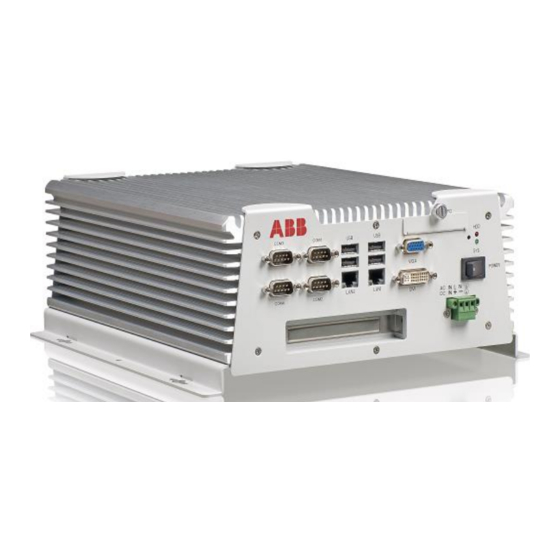
Page 29: Technical Data
1MRS756125 COM600 series, version 4.1 User's Manual Technical data 4.1. Mechanical properties COM600_connectors.png Figure 4.1-1 COM600 interfaces shown in a high voltage model. The COM600 low voltage model includes the same interfaces but without the AC text. The technical data of COM600 is presented in the following tables. - Page 30 COM600 series, version 4.1 1MRS756125 User's Manual Description Value Power consumption at start-up 220 W Table 4.1-3 Power supply, low voltage Description Value nominal 24 .. 60 V DC variation 80..120% of U (19 .. 72 V DC) Power consumption Typical 25 W (with 24 V DC), max.
- Page 31 1MRS756125 COM600 series, version 4.1 User's Manual Description Standard Degree of protection by According to IEC 60529 enclosure Clearance and creepage dis- According to IEC 60255-5 tances Table 4.1-8 Power supply and module tests Description Standard Auxiliary voltage According to IEC 60255-1 Aux.
- Page 32 COM600 series, version 4.1 1MRS756125 User's Manual Description Standard Conducted radio frequency According to IEC 61000-4-6 and IEC 60255-22-6 disturbance • 10 V (80% ampl. mod.) • f= 150 kHz...80 MHz Power frequency (50 Hz) mag- According to IEC 61000-4-8, 300 A/m, continuous...
- Page 33 1MRS756125 COM600 series, version 4.1 User's Manual Description Standard Storage test According to IEC 60068-2-48 Test values: • 72 h at +70ºC • 72 h at -40ºC Table 4.1-13 Mechanical tests Description Standard Vibration tests According to IEC 60068-2-6 and IEC 60255-21-1 •...
-
Page 34: Software Properties
COM600 series, version 4.1 1MRS756125 User's Manual Table 4.1-16 RoHS compliance Complies with the RoHS directive 2002/95/EC 4.2. Software properties The software properties of COM600 are presented in the following tables. Table 4.2-1 Communication protocols Master protocol Slave protocol DNP3 LAN/WAN... - Page 35 1MRS756125 COM600 series, version 4.1 User's Manual Combined Overcurrent and Earth-fault Relay SPAJ 141 C Combined Overcurrent and Earth-fault Relay SPAJ 142 C Combined Phase and Neutral Overcurrent Relay SPAJ 144 C Stabilized Differential Relay SPAD 346 C SACO 16D series units...
-
Page 36: Mounting Of Com600 Computer
COM600 series, version 4.1 1MRS756125 User's Manual 4.3. Mounting of COM600 computer The COM600 computer is designed for mounting at a control panel. To mount the COM600 computer to the wall-mount kit: 1. See Figure 4.3-1 for mounting instructions. 2. After the brackets have been installed, fasten four screws on each bracket. -
Page 37: Disposing Of Com600
1MRS756125 COM600 series, version 4.1 User's Manual 3. Select Integrated Peripherals from the main SETUP menu. Use the cursor keys for moving and enter key for selection. 4. Select SuperIO Device from the next menu. 5. On the SuperIO Device configuration page, go to the COM2 Select parameter and press ENTER. - Page 38 COM600 series, version 4.1 1MRS756125 User's Manual 1. Polybutylene terephthalate 2. Polycarbonate 3. Polypropene...
-
Page 39: Installation
1MRS756125 COM600 series, version 4.1 User's Manual Installation 5.1. About this section This section describes the installation and uninstallation of SAB600, the installation of the touch screen, and modifying and setting up of the COM600 computer. For more detailed instructions on installation of the gateway components, refer to the 1.10, Related documents. -
Page 40: Updating Sab600
10. The installation wizard will next install the Microsoft SQL Server, if it is not already installed on your PC. 11. Restart your computer. Start SAB600 by selecting Start > Programs > ABB > Station Automation Builder 600 > SAB600 from the Windows task bar. Installing CoDeSys programming environment The SAB600 installation DVD includes also the CoDeSys programming environment. -
Page 41: Setting Up The Com600 Computer
1MRS756125 COM600 series, version 4.1 User's Manual To convert a project: 1. Open the old project in the new SAB600. The conversion wizard is launched auto- matically. Follow the wizard instructions. 2. If the conversion wizard was canceled, you can run the conversion by right-clicking on the Gateway object and selecting Convert project. - Page 42 COM600 series, version 4.1 1MRS756125 User's Manual By default, response to the ping command is blocked by the firewall. To allow ping response, change the Allow incoming echo requests configuration setting in the firewall's Advanced ICMP Settings. Table 5.5.1-1 shows the default IP addresses for the LAN ports.
- Page 43 2. Double-click SAB600 on the list and change the Action property to Block the connection. To disable access by disabling the remoting service: 1. Select Control Panel -> Administrative Tools -> Services -> ABB COM600 Remoting Server. 2. Right-click and select Properties.
- Page 44 To change the port number used for the communication from SAB600 to the COM600 computer: 1. Modify the Port Number property of the Gateway object in the SAB600 project. 2. In COM600 computer, select Start -> All Programs -> ABB -> SetRemotingPara- meters. 3. Set the port number in Set Remoting Parameters utility.
-
Page 45: Configuring Com600 Without Keyboard And Mouse
1MRS756125 COM600 series, version 4.1 User's Manual If multiple network adapters are used in SAB600 computer, you must specify the one that is used for the COM600 communication. In the Set Remoting Parameters utility, select the IP address of the SAB600 network adapter used for the COM600 communic- ation. -
Page 46: Uninstalling Sab600
COM600 series, version 4.1 1MRS756125 User's Manual In the COM600 Web HMI, navigate to Communication > Security Settings > Remote desktop settings. Select one of the allow connections options and click Apply. Remote desktop connections will now be enabled for the COM600 computer. -
Page 47: Turning Off Com600 Computer
Microsoft SQL Server and .Net Framework. Removing these programs may infect the functionality of other ABB applications installed on your PC. Uninstalling CoDeSys 1. To open the Add or Remove Programs dialog, select Start > Settings > Control Panel >... -
Page 48: Configuration
COM600 series, version 4.1 1MRS756125 User's Manual Configuration 6.1. Opening a project in Station Automation Builder 600 This section describes the configuration tasks common to all OPC servers, and gives an overview of the configuration tasks related to OPC clients. -
Page 49: Recommended Maximum Configuration
1MRS756125 COM600 series, version 4.1 User's Manual description. Data objects include configuration properties, that contain cross-referencing information between protocol and the OPC/IEC 61850. Process data is connected to a Gateway client using a Cross-References function available in the client IED object. Data objects that are transferred to the client are dragged from the servers on the structure to the function tool. - Page 50 COM600 series, version 4.1 1MRS756125 User's Manual 1. Select File > Open/Manage Project..2. In the Open/Manage Project dialog, select the required location for the project: • Projects on my computer • Projects on network 3. Select New Project on the left.
-
Page 51: Building And Configuring Object Structures
1MRS756125 COM600 series, version 4.1 User's Manual 1. Building the object tree and configuring the object properties for OPC servers (process communication). 2. Building the substation object tree and configuring the object properties for HMI functions. 3. Activating COM600 with a new configuration. -
Page 52: Substation Structure For Hmi
COM600 series, version 4.1 1MRS756125 User's Manual point, make sure that you have already created and configured the event and scale objects. One instance of IEC 61850 OPC Server is always mandatory. For more detailed information on adding objects to the object tree, refer to the appropriate protocol manual (see 1.10, Related documents). -
Page 53: Configuring Object Properties
1MRS756125 COM600 series, version 4.1 User's Manual ClientComStruc.jpg Figure 6.4.2.4-1 Example of OPC client communication structure The OPC client object is added to the same hierarchy level as the OPC server, see Fig- ure 6.4.2.4-1. Below the OPC client object, you can add only channel and device objects. - Page 54 COM600 series, version 4.1 1MRS756125 User's Manual ObjProp.png Figure 6.4.2.5-1 Example of object properties 3. Select the property you want to configure. Depending on the property value type, configuring is always done either by • selecting a predefined value from a drop-down combo box, or •...
-
Page 55: Scl Import Function
1MRS756125 COM600 series, version 4.1 User's Manual Browse to a new configuration file from the appearing dialog. Select the file and click Open. Select the device to import from the drop-down list. You can preview the configur- ation on the right. - Page 56 COM600 series, version 4.1 1MRS756125 User's Manual 4. Select the file and click Open. 5. In the dropdown menu, select the OPC Server, subnetwork or IED, and accesspoint (depending on whether the SCL import has been selected from OPC Server or IED object) to be imported.
- Page 57 1MRS756125 COM600 series, version 4.1 User's Manual SCLImport_communicationOptions.png Figure 6.4.2.6-3 Communication options You can select the following options: • Filter Data Objects that don't belong to DataSet: By selecting this option, you can enhance performance. This option limits the amount of data objects being created in SAB600, meaning that if a data object does not belong to any data set, it will not be created in to the SAB600.
- Page 58 COM600 series, version 4.1 1MRS756125 User's Manual • Check Report Control Block for Client Identity: This option imports IEDs from the file in which the Report Control Blocks' client identity matches the selected OPC Server. • Check Configuration Revisions: By selecting this option, the configuration revision attributes of the project are compared with the SCL file to be imported.
- Page 59 1MRS756125 COM600 series, version 4.1 User's Manual SCLImport_substationOptions.png Figure 6.4.2.6-4 Substation options 2. Click Next to proceed to the Configure Alarm and Event Template page or Import if you do not want to change options in the following pages. Configure Alarm and Event Template 1.
- Page 60 COM600 series, version 4.1 1MRS756125 User's Manual SCLImport_AETemplate.png Figure 6.4.2.6-5 Alarm and Event Template You can also create your own templates if you are familiar with the issue: • Browse to C:\PCMDataBases\COM600\TemplateManager. • Copy the AETemplatephasetrippingmapping.xml file from the folder to the directory and give it a meaningful name.
- Page 61 1MRS756125 COM600 series, version 4.1 User's Manual SCLImport_PFTTemplate.png Figure 6.4.2.6-6 Parameter Filtering Tool Template You can use the Parameter Filtering Template to set predefined parameters for the IED. • If you want to use the parameter filtering tool template when importing the IED, select the Use Template checkbox.
- Page 62 COM600 series, version 4.1 1MRS756125 User's Manual SCLImport_SLDTemplate.png Figure 6.4.2.6-7 SLD Template You can use the SLD template to set the predefined substation structure for the IED. • If you want to use the SLD template when importing the IED, select the Use Template checkbox.
-
Page 63: System Consistency Check
1MRS756125 COM600 series, version 4.1 User's Manual SCLImport_SSTTemplate.png Figure 6.4.2.6-8 Summary Table Template You can use the Summary Table Template to set predefined summary tables for IEDs in Substation and Bay objects. • If you want to use the Summary Table template when importing the IEDs, select the Use Template checkbox. - Page 64 COM600 series, version 4.1 1MRS756125 User's Manual for data model is modeled on the LD0\LLN0\NamPlt\configRev object. It is the most important indicator of the configuration revision. Additionally, each Report Control block has a confRev attribute that defines the revision and the DataSet of RCB. System Consistency Check checks each LDs LLN0\NamPlt\configRev and confRev of each RCB.
- Page 65 1MRS756125 COM600 series, version 4.1 User's Manual SCC_GUI.png Figure 6.4.2.7-1 System Consistency Check view SCC_Options.png Figure 6.4.2.7-2 Options view The Options view allows you to select same importing options that are available in the SCL Import tool. It is recommended that same options are used with both functions.
-
Page 66: Cross-References Function
COM600 series, version 4.1 1MRS756125 User's Manual SCC details.bmp Figure 6.4.2.7-3 Details view The Details view shows added or deleted LDs and RCBs. Additionally, it shows the modifications to the content of LD or RCB. 6.4.2.8. Cross-References function Data objects are added differently for OPC clients than for the upper level objects. Drag and drop the data objects you need from an OPC server to the slave. - Page 67 1MRS756125 COM600 series, version 4.1 User's Manual CrossReferencesFunction.jpg Figure 6.4.2.8-1 Cross-References function In the Cross-References function, you can use a filter file to leave out some of the data objects to be connected to the slave device. Select the filter file from the drop-down menu under Active Filter. If there are no filter files listed in the drop-down menu, you can create your own filter file by clicking Modify Filter File.
- Page 68 COM600 series, version 4.1 1MRS756125 User's Manual For more detailed instructions on configuring the data object properties in the Cross- References function, refer to the slave protocol user’s manuals listed in 1.10, Related documents. Template based Cross-Referencing The purpose of this functionality is to provide a template functionality for slave addressing for IED types.
- Page 69 1MRS756125 COM600 series, version 4.1 User's Manual When template functionality is enabled, dropped data objects are compared to the data in the template. If matching data is found, the address properties are modified according to template. IED_Base_Addresses.png Figure 6.4.2.8-3 Base addresses Base addresses The Base Address determines the base address value for each signal in template.
- Page 70 COM600 series, version 4.1 1MRS756125 User's Manual uplink_address_addrow.png Figure 6.4.2.8-4 Uplink addresses Filter Functionality in Uplink Address Table • Import - Imports another template file from hard drive • Export - saves current template file to hard drive • CID Import - creates base template based on datasets in imported CID file •...
- Page 71 1MRS756125 COM600 series, version 4.1 User's Manual uplink_address_table.png Figure 6.4.2.8-5 Uplink Address Table Adding Row in Uplink Address Table You can add rows to the template by editing values of the cells in rows marked with *. uplink_address_filter.png Figure 6.4.2.8-6...
- Page 72 COM600 series, version 4.1 1MRS756125 User's Manual Editing values Ideally you don't have to add any signals to the template manually. All cells are editable, but you are supposed to edit only the Index columns. These columns represent signal addresses to be for that IED type.
-
Page 73: Configuration Of Station/Remote Switch
1MRS756125 COM600 series, version 4.1 User's Manual 6.4.3. Configuration of Station/Remote switch Each IED and logical device in the OPC Server has a configuration parameter defining the OPC node path for the S/R switch that is used for that IED/logical device. If a logical device does not have an S/R switch path configured, the path defined in the IED is used instead. - Page 74 COM600 series, version 4.1 1MRS756125 User's Manual To create an alarm group: 1. Create virtual Application OPC server. 2. Create Virtual Subnetwork. 3. Create Virtual IED. 4. Create Virtual LD. 5. Create LN. 6. Create GroupAlarm SPS object If you are going to create several Group Alarm objects, rename each object with a unique name within LN.
-
Page 75: Configuring Com600 Event Printer
1MRS756125 COM600 series, version 4.1 User's Manual If the alarm group contains any signal with bad or unknown quality then the alarm group is active. The quality of the group alarm is always good. • Unknown Signal States Ignored Group alarm is calculated using only the signals with good/known quality. If no signals have good/known quality then the group alarm is inactive. -
Page 76: Using Scales
COM600 series, version 4.1 1MRS756125 User's Manual Property Value Description Event Printer Code Page Specifies the code page that is used to convert strings (event) to be printed into bytes that are sent to the printer. Event Printer Enabled False Specifies whether the event printer functionality is in use. -
Page 77: Creating Scales
1MRS756125 COM600 series, version 4.1 User's Manual Before you can connect a scale to a data object, add and con- figure the scale in SAB600. Add and configure the scales before adding and configuring any other objects. 6.4.5.2. Creating scales To create scales: 1. - Page 78 COM600 series, version 4.1 1MRS756125 User's Manual 2. The object properties appear now in the Object Properties window, see Figure 6.4.5.3- 3. You can assign the scale with parameter values. ScaleDefObjProp.jpg Figure 6.4.5.3-1 Object properties of the scales Table 6.4.5.3-1 Scales...
-
Page 79: Backing Up And Restoring
1MRS756125 COM600 series, version 4.1 User's Manual Property/Para- Value or value range/ Default Description meter 03 Out Value Scaled value 04 In Value Value to be scaled 04 Out Value Scaled value 05 In Value Value to be scaled 05 Out Value... -
Page 80: Scl Export
COM600 series, version 4.1 1MRS756125 User's Manual To retrieve and existing configuration: 1. Right click the Gateway object in the Communication view. 2. Select Management. 3. From Configuration control, click Retrieve COM600 Configuration. 4. In the file view, browse to the location of the required configuration file. -
Page 81: Configuring External Watchdog For Com600
1MRS756125 COM600 series, version 4.1 User's Manual 6.8. Configuring external watchdog for COM600 The communication to the IED used as a watchdog is configured as with any IEDs using SAB600. The IED is configured with SPC or INC type of data object to which the cyclical command is sent. -
Page 82: Installing Intel Teaming Feature To Com600
COM600 series, version 4.1 1MRS756125 User's Manual By default DuoDriver Virtual Adapter name has # character in it. Remove # from the name as it causes problems with the OPC naming. 6.10. Installing Intel Teaming feature to COM600 The Teaming feature is available only if a LAN optional card has been installed in COM600. - Page 83 1MRS756125 COM600 series, version 4.1 User's Manual Intel_Pro_Port_Server_Adapter.JPG Figure 6.10-1 Opening the Teaming tab 6. Select Team this adapter with other adapters and click New Team. 7. Specify a name for the team and click Next. New_Team_Wizard.png Figure 6.10-2 New Team Wizard...
-
Page 84: Configuring Data Historian
COM600 series, version 4.1 1MRS756125 User's Manual 8. Unselect Intel(R) 82657LM Gigabit Network Connection adapter and select both Intel(R) PRO/1000 MT Dual Port Server Adapters. Click Next. 9. Select Switch Fault Tolerance to a team mode and click Next. Switch_Fault_Tolerance.JPG Figure 6.10-3 Switch Fault Tolerance selection... - Page 85 1MRS756125 COM600 series, version 4.1 User's Manual 2. The following file browser dialog opens. rtdbtimezone.bmp Figure 6.11.1-1 Time Zone Definition 3. Select the time zone from the list and click Open. 4. Reboot the computer so that the service processes notice the new setting.
-
Page 86: Configuring Data Historian Measurements And Signals
COM600 series, version 4.1 1MRS756125 User's Manual HMI_Data_Historian_menu.bmp Figure 6.11.1-2 Data Historian menu item shown in Web HMI To enable the Vtrin installation to client computers, select Start -> All Programs -> Data Historian -> Change Vtrin IP Address from the COM600 computer start menu. - Page 87 1MRS756125 COM600 series, version 4.1 User's Manual DataHistorianConfiguration.bmp Figure 6.11.2-1 Opening Data Historian Configuration tool The Trend Configuration dialog opens. DataHistorianConfigurationTool.bmp Figure 6.11.2-2 Data Historian Configuration tool Drag and drop data objects to the Data Historian Configuration tool, where they are displayed as rows.
-
Page 88: Security Event List Backup
COM600 series, version 4.1 1MRS756125 User's Manual Levels columns, although the values are set according to the values defined for the data object. 4. You can modify the editable values. Check the values for the History Levels column from COM600 Data Historian Operator's Manual. - Page 89 1MRS756125 COM600 series, version 4.1 User's Manual The task is named “\COM600\COM600EventStoreBackup” in the Windows task scheduler. It is disabled by default. When enabled, the task launches the COM600EventStoreBackup.bat script with the intended backup location as the input parameter. To automatically backup COM600 Security event list 1.
-
Page 90: Operation
The COM600 Management tool displays the license information for COM600 under License Information. The license and the protocols it supports have been predefined before the COM600 computer has been handed over by ABB. The following information is shown in the window: •... -
Page 91: Using Web Site Security Certificates
• if WebHMI is enabled. To update the license with a new set of protocols, order a new license from ABB and update it to COM600 with SAB600. To update the license: 1. Open the Management tool from the Gateway object in SAB600. -
Page 92: Using Self-Signed Certificates With Internet Explorer 8 And 9
COM600 series, version 4.1 1MRS756125 User's Manual Select Start > Control Panel > Administrative Tools > Internet Information Services. In the tree view, select the computer and then Web Sites. Right-click Default Web Site and select Properties. d. In the Properties dialog, select Directory Security > View Certificate > Details >... -
Page 93: Diagnostics
1MRS756125 COM600 series, version 4.1 User's Manual 7.4. Diagnostics 7.4.1. General about diagnostics SAB600 provides comprehensive functions for diagnosing the operation of the Gateway. This includes communication diagnostics with monitoring the communication channel, diagnostic counters, and IED-specific communication status and diagnostic counters. It is also possible to monitor and control process data and follow the data flow on the Gateway using diagnostic functions of SAB600. -
Page 94: Channel Online Diagnostics With Analyzer
COM600 series, version 4.1 1MRS756125 User's Manual EventDial.jpg Figure 7.4.1-2 An example of a SPA event log file 7.4.2. Channel online diagnostics with Analyzer The Analyzer function is available in the channel diagnostics for most of the protocols. The Analyzer function shows transmitted and received telegrams in hex format. In addition, it can show control signal changes for serial communication protocols. -
Page 95: Diagnostic Services Of Opc Servers And Clients
1MRS756125 COM600 series, version 4.1 User's Manual 2. Select Data object diagnostics from the shortcut menu, see Figure 7.4.3-1. The Data object diagnostic dialog opens. 3. Drag and drop data objects from the object tree to the Data object diagnostics. -
Page 96: Signal Diagnostics
COM600 series, version 4.1 1MRS756125 User's Manual LON_Clock_Master_Online_diagnostics.jpg Figure 7.4.4-1 An example of LON Clock Master online diagnostics For more detailed information and instructions on controlling and monitoring channel and device communication, refer to the respective user’s manual for the client or server (see 1.10, Related documents). -
Page 97: Diagnostic Web Server
1MRS756125 COM600 series, version 4.1 User's Manual IEC101AEClient.jpg Figure 7.4.5-1 IEC101 Slave OPC Client Diagnostic AE client 7.4.6. Diagnostic Web Server The Diagnostic Web Server of the Gateway provides an overall view of the communic- ation status of the Gateway and the possibility to monitor the diagnostic counters of the communication channels/subnetworks and IED communication. - Page 98 COM600 series, version 4.1 1MRS756125 User's Manual COM610_HMI.jpg Figure 7.4.6-1 An example of a web page from the Gateway diagnostic web server...
-
Page 99: Index
1MRS756125 COM600 series, version 4.1 User's Manual Index Activating COM600 ..................... 90 backup ....................... 79 building object tree ...................... 51 CID export ......................80 COM600 computer accessing ....................... 41 mounting ......................36 remote desktop ....................42 user accounts ....................43 configuration .................... - Page 100 COM600 series, version 4.1 1MRS756125 User's Manual event printer ....................... 27 configuring ..................... 75 exporting configuration files .................... 80 project ......................79 functionality Gateway ......................16 HMI ....................... 17 Gateway functionality ....................16 Grouping Alarms alarms ......................73 headless COM600 ....................45 accessing .......................
- Page 101 1MRS756125 COM600 series, version 4.1 User's Manual object properties configuration ....................53 object tree ......................49 building ......................51 OPC client adding ......................52 structure ......................19 OPC server structure ......................18 process data ...................... 48 project exporting ......................79 project conversion ....................
- Page 102 COM600 series, version 4.1 1MRS756125 User's Manual Station/Remote switch ..................24 structure OPC client ...................... 19 OPC server ....................18 substation structure creating ......................52 system consistency consistency ....................63 updating license ....................91...
- Page 104 Contact us ABB Oy Distribution Automation P.O. Box 699 FI-65101 VAASA, FINLAND Tel. +358 10 22 11 Fax. +358 10 224 1094 ABB Inc. Distribution Automation 655 Century Point Lake Mary, FL 32746, USA Tel: +1 407 732 2000 Fax: +1 407 732 2335...