Mitsubishi Electric AG-150A Instruction Book
Air-conditioner control system centralized controller
Hide thumbs
Also See for AG-150A:
- Instruction book (100 pages) ,
- Installation manual (12 pages) ,
- Installation manual (34 pages)
Table of Contents
Advertisement
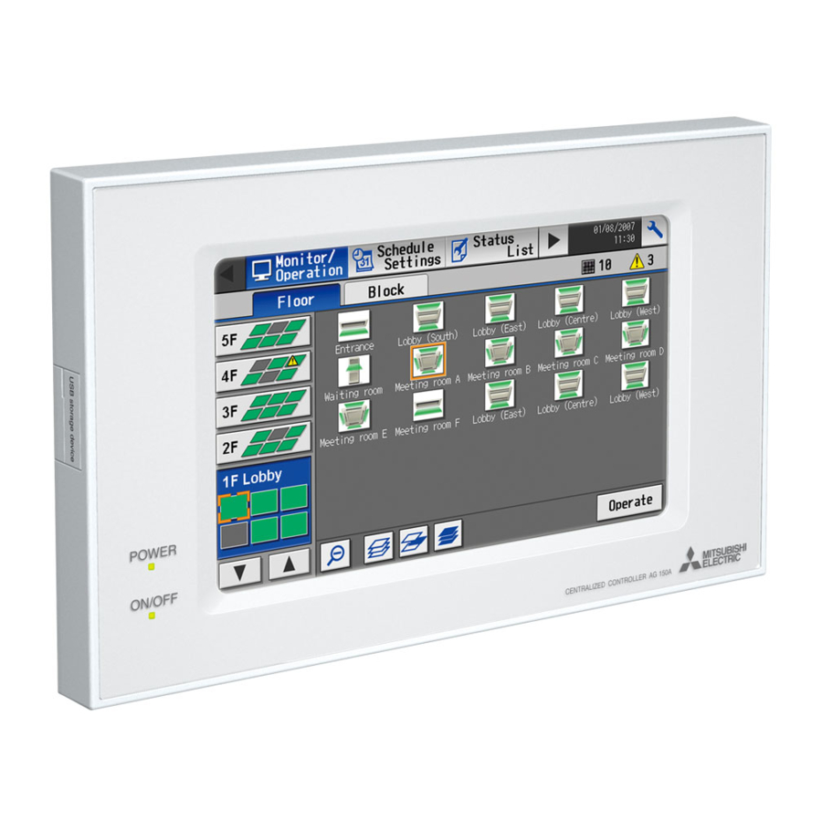
Air-conditioner Control System
Centralized Controller
AG-150A
AG-150A-A
Before using the controller, please read this Instruction Book carefully to ensure proper operation.
Retain this manual for future reference.
1. Safety precautions .............................................................. 1
2. Introduction ......................................................................... 2
3. Product features ................................................................. 3
4. Component names and display screen names................... 6
5. Initial Start up .................................................................... 14
6. User operation .................................................................. 24
CENTRALIZED CONTROLLER AG-150A
7. Initial Settings ................................................................... 52
8. Function 1 ......................................................................... 81
9. Function 2 ......................................................................... 87
10. User Setting ...................................................................... 93
11. Maintenance screen ......................................................... 95
12. Cleaning the touch panel ................................................ 104
13. External input/output function ......................................... 105
14. LAN connection function ................................................. 106
15. Specifications.................................................................. 107
16. Error code list.................................................................. 108
Instruction Book
5-1
Expansion controller (PAC-YG50ECA).................... 14
5-2
Expansion controller (PAC-YG50ECA).................... 16
5-3
connection to Expansion controllers ........................ 19
6-1
Operation condition monitoring................................ 26
6-2
remote controller...................................................... 29
6-3
Setting Schedules.................................................... 35
6-4
Checking the List of Malfunctioning Units................ 48
6-5
Filter Sign................................................................. 50
6-6
Checking the Malfunction Log ................................. 51
7-1
Bringing up the settings screen ............................... 52
7-2
Locking the screen................................................... 55
7-3
Setting the Current Date and Time .......................... 56
7-4
Register the license ................................................. 57
7-5
Setting the Basic Information................................... 58
7-6
Network Setting ....................................................... 60
7-7
Group Setting........................................................... 64
7-8
Interlocked Setting ................................................... 68
7-9
Block Setting............................................................ 70
7-10 Floor Layout Setting................................................. 72
7-11 Checking the refrigerant systems ............................ 77
7-12 Advanced settings ................................................... 78
8-1
Measurement Setting............................................... 81
9-1
External temperature interlock................................. 87
9-2
Night setback function ............................................. 90
10-1 Setting the Maintenance User ................................. 93
10-2 Setting the Building Manager................................... 94
11-1 Copying the data to a USB memory ........................ 95
11-2 Reading setting data from USB memory ................. 97
11-3 Setting data.............................................................. 98
11-4 Operational data .................................................... 100
11-5 Adjusting the touch panel ...................................... 103
13-1 External input function ........................................... 105
13-2 External output function ......................................... 106
16-1 M-NET error code .................................................. 108
16-2 EC line error code.................................................. 112
WT05369X15
Ver. 2.95
Advertisement
Table of Contents

Related Manuals for Mitsubishi Electric AG-150A


Summary of Contents for Mitsubishi Electric AG-150A
-
Page 1: Table Of Contents
Expansion controller (PAC-YG50ECA)....14 Initial start up for a system with connection to an Expansion controller (PAC-YG50ECA)....16 Connecting multiple AG-150A to a system with connection to Expansion controllers ......19 6. User operation ..............24 Operation condition monitoring........ 26 Operation setting/Prohibition setting from local remote controller............ -
Page 2: Safety Precautions
Do not spray insect sprays or sprays with flammable Use a security device such as a VPN router when propellants to the controller. connecting the AG-150A or AG-150A-A to the Internet To avoid the risk of fire or explosion, do not place to prevent unauthorized access. -
Page 3: Introduction
The terms “Group,” “Block,” and “EC” used in this manual are defined as follows: Group: Group is a group of air conditioning units and controllers and is the smallest unit that the AG-150A and AG-150A-A can control. The maximum number of units and controllers that each group can contain is 16. -
Page 4: Product Features
3. Product features The controller described in this manual is a centralized controller that can be operated over the Web. Any connected air conditioning systems can be operated or monitored directly from the controller or over the Web using browser software. Refer to the Web browser operation manual (separate volume) for how to use this functions. - Page 5 The address of the unit in error, error code, and the address of the unit that detected the error will Error appear. Up to 384 errors can be stored in memory. (128 errors per AG-150A or Expansion controller (64 unit Error history monitor errors, 64 communication errors)) Outputs signals (run/stop, error) to an external device.
- Page 6 *2: The maximum number of the controllable units varies, depending on the number of channels used by DIDO controllers. *3: “Air To Water (PWFY)” on the AG-150A screen indicates Booster unit group and Water HEX unit group. *4: Up to 6 general equipments can be connected to each DIDO controller (PAC-YG66DCA).
-
Page 7: Component Names And Display Screen Names
4. Component names and display screen names Note: Power indicator (AG-150A) Before using the AG-150A, remove Not lit ... Power is turned off. the protective sheet on the surface Lit ..Power is turned on. cover. CAUTION If the protective sheet is left on the screen, the sheet may stick to the LCD and cause malfunctions. - Page 8 Important • If nothing appears on the display after touching the touch panel several times, the LCD backlight may be damaged. Since continued use may cause malfunctions, stop the operation, and contact the service center. • Touching two points simultaneously will be interpreted as pressing a different point. To avoid malfunctions, only touch one point at a time.
- Page 9 <Monitor/Operation> Block display (P27) Floor layout (detailed icons) (P26) Measurement display (P27) Touch With connection to AI and PI controllers Touch Floor layout (simplified icons) (P27) Air conditioning system operation screen (P29) HWHP display (P27) Touch HWHP operation screen (P33) Login (P52) With connection to HWHP (CAHV) units –...
- Page 10 <Schedule Settings> • Setting the schedule without a license registration Schedule setting screen (floor layout) Weekly(P35) Weekly schedule screen(P38) Schedule setting screen (block display) Weekly(P36) With connection to HWHP (CAHV) units Schedule setting screen (air conditioning units)(P39) With connection to HWHP (CAHV) units Schedule setting screen (HWHP display) Weekly(P37) Touch...
- Page 11 <Schedule Settings> • Setting the schedule with a license registration Touch Schedule setting screen (block display) Season setting screen(P43) Ex. Weekly 1, 2, 3, 4, 5 (P41) Weekly schedule screen(P38) Schedule setting screen (floor layout) Ex. Weekly 1, 2, 3, 4, 5 (P41) Annual schedule pattern setting screen(P44) Annual schedule screen(P44) Schedule setting screen (HWHP...
- Page 12 <Status List> Touch [Filter Sign] Malfunction(P48) Touch [Malfunction] Touch Touch Login(P52) Filter sign(P50) <Log> Touch [Communication Error] Touch Unit error(P51) [Unit Error] Touch Touch Login(P52) Communication error(P51) – 11 –...
- Page 13 <Function 1> Measurement (P81) <Function 2> Touch [Setback] Touch [Ext Temp Interlock] Ext Temp Interlock (P87) Setback (P90) <User Info> Touch [Building Manager] Touch [Maintenance User] Maintenance User (P93) Building Manager (P94) – 12 –...
- Page 14 <Maintenance> Import (P97) Backup (P95) CSV output (P100) Touch Panel Calibration (P103) “Calibration completed.” or Touch [Start calibration] “No operation for one minute.” Calibration (P103) – 13 –...
-
Page 15: Initial Start Up
5. Initial Start up 5-1 Initial start up for a system without connection to an Expansion controller (PAC-YG50ECA) After the power is turned on, the language selection screen will appear. Select the language to be used for display, and then touch [OK]. Note: It will take approximately 20 seconds for the display to appear after the power is turned on. - Page 16 After making the network settings, touch the [Groups] tab, and make the settings. (Refer to Section 7-7 for the details on how to make the group settings.) Make other settings such as block settings and interlocked LOSSNAY settings. Refer to appropriate sections in Chapter 7 on how to make the settings.
-
Page 17: Initial Start Up For A System With Connection To An Expansion Controller (Pac-Yg50Eca)
IP address for the AG-150A. Select the Expansion controller (EC1-EC3) whose settings are to be made from the tab menu. Check that the DB No. on the AG-150A itself and the DB No. of the Expansion Controller match. (The DB No. for the AG-150A can be found on the back of the controller, on the package box, or on the LCD. - Page 18 After the network settings have been made, touch [Groups], select the EC number from the tab menu, and make the group settings for each EC. * The settings for the units that are connected to a different Expansion controller cannot be made. (Refer to Section 7-7 for the details of how to make the settings.) Make other settings such as block settings and interlocked LOSSNAY settings.
- Page 19 After moving to the [Operation/Monitor] screen, the startup screen will appear. Startup takes a maximum of five minutes after the message appears. (It takes about two to three minutes when no communication errors occur.) – 18 –...
-
Page 20: Connecting Multiple Ag-150A To A System With Connection To Expansion Controllers
Controllers with different DB No. cannot be connected to each other. (4) Miscellaneous restrictions • Controllers such as AG-150A connected to a system must have the same settings for the settings such as Group or Interlocked ventilation (LOSSNAY). Different settings for the settings such as Group or Interlocked ventilation (LOSSNAY) cannot be made in a system. - Page 21 Shown below is how to connect two or more AG-150A controllers to a system. Refer to the respective manual for more information about how to connect other types of controllers. (5) Make the settings (e.g., IP address) for the Expansion controller network, and switch on the power.
- Page 22 (10) Make the settings for the Expansion controller IP (10) Make the settings for the Expansion controller IP address, M-NET, and external input. address. • Touch “Save Settings” to confirm that the settings for the M- NET and external input are the same as the ones made for the first unit (master).
- Page 23 (13) Make the settings for the block and group names. (13) Make the settings for the block and group names. The settings for the 2nd and subsequent units do not need to be the same as the settings for the Master unit. (14) Make the settings for the floor layout.
- Page 24 (17) Initial settings are completed. (17) Initial settings are completed. Perform a test run to check for proper settings. Perform a test run to check for proper settings. – 23 –...
-
Page 25: User Operation
6. User operation The following screens are used under user operation. • Floor layout/block display screens ......Displays the operation status (ON/OFF), error status of the air conditioning system, and room temperature. This is the screen that is normally used. •... - Page 26 Accessing the Floor layout, Block display, and Air conditioning unit operation setting screens Refer to Section 6-1 “Operation condition monitoring” (P 26). Zoom-out button Block button Zoom-in button Press Press Floor layout (detailed icons) Floor layout (simplified icons) Press [OK] or Operation button Press [Floor].
-
Page 27: Operation Condition Monitoring
6-1 Operation condition monitoring • This function displays the ON/OFF/Malfunction status of specific units, groups, block, or floor. Weekly schedule number Indicates the weekly schedule number that is Group icon currently effective. Floor-switching button Number of units in error Button used to switch Indicates the number of units the floors that are in error. - Page 28 <Group display (simplified icons)> The following icons indicate the operation status. : On : Off : Error • Pressing the Zoom-in button returns to the screen with detailed icon. • By pressing the floor switching button, air conditioning systems on other floors can be checked.
- Page 29 (This will occur when used with the following M-NET adapter: PAC-SF48/50/60/70/80/81MA-E) * When multiple AG-150A controllers are connected by connecting an Expansion controller to the system, “Schedule setting enabled,” “Schedule setting Not Available,” “During energy-save control,” and “During night setback” will be displayed only on the AG-150A controller that is executing these functions.
-
Page 30: Operation Setting/Prohibition Setting From Local Remote Controller
6-2 Operation setting/Prohibition setting from local remote controller The setting for the control of air conditioning units (LOSSNAY, general equipments, Air To Water (PWFY)) and the permit/prohibit setting from the local remote controller are made on this screen. * The screen will show the status of the units at the time the screen is opened, any change that may take place after the screen is opened will not be reflected. - Page 31 Function Operation method Display 4 Set Air Direction Set the air flow direction 5-directions model with the Up/Down arrows below “Air Direction” function. (Mid 3) (Mid 2) (Mid 1) (Mid 0) (Horizontal) (Swing) (Auto) (Swing and Auto are not available on some indoor unit(s). Depending on the indoor unit four or five air flow directions are available.) 5 Fan speed Use the Up/Down...
- Page 32 (2) Ventilation equipment (LOSSNAY) group 1ON/OFF switch 2Operation mode switch Item selection frame An orange frame appears around the selected item. 3Fan Speed 6Filter sign reset 4Remote controller 5Schedule 8Cancel operation prohibit switch Available/Not Available Function Operation method Display 1 ON/OFF Select the operation An orange frame will appear around the selected button.
- Page 33 (3) Air To Water (PWFY) (Booster and Water HEX unit) group 1ON/OFF switch 2Operation mode switch 3Temperature Item selection frame An orange frame appears around the selected item. 6Circulating water replacement sign reset 4Remote controller 5Schedule 8Cancel operation prohibit switch Available/Not Available Function Operation method...
- Page 34 Function Operation method Display 7 OK Press the OK button to Pressing the OK button saves the setting and takes the screen back to the previous reflect the change. screen (Floor layout or Block display). 8 Cancel Press the Cancel button to Pressing the Cancel button cancels the change and takes the screen back to the cancel the change.
- Page 35 Function Operation method Display 3 Set Temperature Set the temperature by Pressing the Up/Down arrow increases/decreases the temperature by one degree using the Up/Down arrows respectively. below “Set Temp.” The settable temperature range depends on the mode and model. If the Up arrow is touched when the upper limit temperature is displayed.
-
Page 36: Setting Schedules
Weekly schedule for each group can be set. When a license is registered, it is possible to set different weekly (5 types)/annual/today's schedules for each group. * When multiple AG-150A controllers are connected by connecting an Expansion controller to the system, schedule settings for the groups should be made only on one of the AG-150A controllers. - Page 37 (1-3) Block To make the settings for a block or blocks, select the block selection button on the block display screen under the weekly schedule setting screen by touching it. An orange frame will appear around the icons that correspond to the selected blocks. After making the selection, touch the [Edit] button at the right bottom corner of the screen to bring up the weekly schedule screen.
- Page 38 (1-5) HWHP (CAHV) To set the schedule for the HWHP (CAHV) units, touch and select the icon of the group to set its schedule from a list of HWHP (CAHV) units on the weekly schedule setting window. Multiple groups are selectable. Orange frames will appear around the icons of the selected groups.
- Page 39 (2) Select the day of the week Select the days of the week from the weekly schedule setting screen and touch the schedule content button to bring up the schedule content setting screen. The ON/OFF events that are schedules will appear as inverted triangles and triangles ( : ON;...
- Page 40 (4) Copy a schedule to another day of the week or to another group Copy button Paste button To copy the schedule of a given day to another day, select the days of the week from the weekly schedule setting screen, touch [Copy] to select it, select a day to copy the schedule to, and touch [Paste].
- Page 41 • Optimized start-up schedule function Optimized start-up schedule function is a function that starts an air conditioning unit 5 - 60 minutes prior in order to reach the scheduled temperature at the scheduled time. Note: A unit starts 30 minutes prior at the first boot. Note: If the room temperature is measured by the air-conditioner’s suction temperature sensor, the temperature may not be correct when the air-conditioner is inactive and the air is not fresh.
- Page 42 6-3-2 Setting the schedule with a registered license When a license (PIN CODE) is registered, it is possible to set different weekly (5 types)/annual/today’s schedules for each air conditioner group. Moreover, for any weekly/annual/today’s schedule run for a particular day, the priority in which it is run will be from the highest and the order will be [Today’s], [Annual], [Weekly 1], [Weekly 2], [Weekly 3], [Weekly 4], [Weekly 5].
- Page 43 (3) Select the day of the week Select the days of a week from the weekly schedule screen and touch the schedule content button to bring up the schedule content setting screen. Note: When multiple groups are selected, those settings that have been made for each group will not be displayed.
- Page 44 (6) Save the contents of schedule After all the settings have been made, touch the [OK] button to save the schedule settings. Touch the [Cancel] button to go back to the previously saved settings without making any changes. (7) Define the seasons Enable/Disable Weekly 1: Applicable period switching button (Weekly 2)
- Page 45 6-3-2-2 Setting the annual schedule (Applicable only when the license is registered) Selecting [Schedule Setting] from the main menu on the [Main operation screen] will bring up the schedule setting screen. Subsequently, selecting [Annual] from the sub menu will bring up the annual schedule setting screen. You can use the annual schedule to set schedules for days such as public holidays and summer vacation that need to be scheduled differently to the weekly schedule.
- Page 46 (3) Edit the patterns. After selecting the pattern, touch the schedule content button to bring up the schedule content setting screen. Make the settings for the execution time and operation patterns (ON/OFF, operation mode, setting temperature, airflow direction, fan speed, remote controller operation prohibition) on the schedule content setting screen, and then touch the [OK] button.
- Page 47 (6) Save the contents of schedule After all the settings have been made, touch the [OK] button to save the schedule settings. Touch the [Cancel] button to go back to the previously saved settings without making any changes. 6-3-2-3 Setting the current date schedule Selecting [Schedule Setting] from the main menu on the [Main operation screen] will bring up the schedule setting screen.
- Page 48 (3) Copy a schedule to another group To copy the settings of the current day schedule in one group to another, select the group from the current day schedule setting screen (Floor layout or block display screen), touch [Copy], select a group to copy the schedule to, and touch [Paste].
-
Page 49: Checking The List Of Malfunctioning Units
6-4 Checking the List of Malfunctioning Units Touch the [Status list] in the main operation screen menu, and then touch [Malfunction] to see a list of units that are currently in error. Note: If an error occurs, check the unit address, error code and error description before consulting your dealer or service center. 1Floor name or Block name Floor name or... - Page 50 When an error is reset, units other than the ones in error may come to a stop. Types of units in error and the affected units that will stop Units in error Units that stop AG-150A (EC) None Outdoor unit All indoor units that are connected to the outdoor unit in error...
-
Page 51: Checking The List Of Units With A Triggered Filter Sign
6-5 Checking the List of Units with a Triggered Filter Sign Touching [Status List] on the Main operation screen and then touching [Filter signs] in the sub menu will bring up a list of units whose filter sign is turned on. 1Floor name or Block name 4Number of... -
Page 52: Checking The Malfunction Log
6-6 Checking the Malfunction Log Touch the [Unit error] in the sub menu under [Log] on the main operation screen to see the unit error history (latest 64 events). Touch [Communication error] in the sub menu to see the M-NET transmission error history (latest 64 events). 2Communication 1Unit error log error log... -
Page 53: Initial Settings
7. Initial Settings 7-1 Bringing up the settings screen Touching the Setting Change button on the top right hand on the Main menu will bring up the Login screen. Touch “User Name” and “Password” on the screen, and enter them. Touch the Login button. If the user name and the password match, the Setting Change screen will appear. - Page 54 Keyboard Screen The screen below is used to enter characters and numbers on the Initial Settings screen. 2Arrow Button 1Text display field 3Delete button 4Keyboard 7Numeric character/ symbol button 8OK button 6Alphabetic character (lower case) button 9Cancel button 5Alphabetic character (capital) button Item Description...
- Page 55 Handwriting input screen When “Japanese” or “Chinese” is selected, characters can be input by using a handwriting pad. 3Input candidate character button 1Handwriting input area 4Memorized input word button 5Handwriting 2Clear button switch button Item Description This area is used to input characters. Handwrite a character in this area.
-
Page 56: Locking The Screen
7-2 Locking the screen Locking the screen prevents unauthorized users from accessing. Screen lock function is available only when [Use] is selected on the [Unit information] screen of [Initial setting] screen. Note: The initial setting is set to [Do not use]. If [Use] is selected, the screen locks when the backlight is off (after 10 minutes of not pressing anything). -
Page 57: Setting The Current Date And Time
Note: The clock setting made on the screen below will be reflected on the clocks on other units that are connected to the M-NET line, on the Expansion controllers (PAC-YG50ECA), and on the AG-150A controller whose “Time master setting” is set to Sub. -
Page 58: Register The License
Touch the “Trial” button to register a one-day license that is valid for one day from the time the button is touched. (Web Monitor License Only) Note: When multiple AG-150A controllers are connected by connecting an Expansion controller to the system, the license to use the optional functions is required only for the AG-150A controller on which the functions are actually used. -
Page 59: Setting The Basic Information
(2) Press the [Unit ID] button and enter the ID number for AG-150A in six numerical characters (single byte) or less. Use this setting when you want to control multiple AG-150A units with unit IDs. The unit ID that is entered here will be used on the display screen of the software that controls multiple AG-150A units and for the sender ID in the body of error messages. - Page 60 (7) Make the room temperature display setting. Touching the button cycles through [Hide], [Always show], and [Show during operation]. *This setting is valid only on the AG-150A's LCD screen (except the display of water temperature on the Air To Water (PWFY) unit).
-
Page 61: Network Setting
7-6-1-1 Settings for when the AG-150A is connected to a dedicated LAN (1) Set the IP address for AG-150A. Enter the IP address on the keyboard that appears when the IP address input button is touched. If the LAN wiring has been newly set up, allocate IP addresses to the AG-150A units in a sequential order starting with [192.168.1.1]. - Page 62 7-6-3 External input Setting The external input function allows for a batch operation (start/stop) of the air conditioning units that are connected to the AG-150A via the external input/output adaptor (PAC-YG10HA; sold separately), using contact and pulse signals. Pressing the “External Input Setting” button toggles through the following options: Not in use, Emergency Stop (Level signal), ON/OFF (Level signal), and ON/OFF/Prohibit/Permit (Pulse signal).
- Page 63 EC tab menu, and make the settings for the AG-150A and the connected ECs. First, select [AG-150A] from the EC tab menu, and make the settings for the IP address, subnet mask, and gateway address of the AG- 150A.
- Page 64 (2) When K-Control air conditioners are connected, enter the M-NET address of K transmission converter in the [K Converter Address] field. * When K-control units are connected, set the AG-150A M-NET address to “0.” * The addresses of the K-control indoor units should be larger than those assigned to indoor units M-transmission indoor units.
-
Page 65: Group Setting
Note: If the system is connected to the TG-2000A, make all settings and changes from the TG-2000A so that the data in TG-2000A and AG-150A will match. Note: A contact on the genera interface device is regarded as one unit. The number of units that can be connected to AG-150A is up to 50. Note: Different models cannot be in the same group. - Page 66 (2) To change the icons, touch the icon selection button, and select the desired icon from the ones that appear. Item selection frame An orange frame appears around the selected unit(s). (3) To register a remote controller to a group, touch the remote controller selection button to bring up the remote controller selection screen, and then touch the numbers that are assigned to the units to resister.
- Page 67 (2) To change the icons, touch the icon selection button, and select the desired icon from the ones that appear. (3) In the [Allow Operation] section, select whether to enable or disable the ON/OFF operation on the LCD on the AG-150A Web browser or on the TG-2000A operation screen.
- Page 68 (4) In the [Monitor] section, select whether to display I/P to or from the general equipment on the monitor screen. General equipment display setting button (5) Press the [Save setting] on the group setting screen to save the settings. 7-7-4 Registering general equipment in the group for a system with connection to an Expansion controller (PAC-YG50ECA) From the menu bar on the Setting change screen, touch [Initial Settings] >...
-
Page 69: Interlocked Setting
Note: If the user logs in as a building manager, the operations may be prohibited. Note: If the system is connected to the TG-2000A, make all settings and changes from the TG-2000A so that the data in TG-2000A and AG-150A will match. LOSSNAY button... - Page 70 (2) Touch the Interlocked indoor unit button to bring up the interlocked indoor unit selection screen, and touch the number assigned to the unit to register. An orange frame will appear around the selected items. Touch again to deselect the selected items. Touch again to deselect the selected item (no orange frame).
-
Page 71: Block Setting
Note: If the user logs in as a building manager, some of the operations may be prohibited. Note: If the system is connected to the TG-2000A, make all settings and changes from the TG-2000A so that the data in TG-2000A and AG-150A will match. Block No. - Page 72 • Making the block settings for a system with connection to an Expansion controller (PAC-YG50ECA) To perform a batch monitoring/control of multiple air conditioning unit groups, the groups need to be registered to a block. Touch [Blocks] on the screen that appears when [Initial Settings] on the menu bar in the setting change screen to register groups to a block. Note: Blocks are used as a unit of control for energy-saving and peak-cut control.
-
Page 73: Floor Layout Setting
7-10 Floor Layout Setting To change the floor layout on the main operation screen or to change the display position of the groups on the floor, touch the [Floor layout] tab in the setting change screen. Note: If the user logs in as a building manager, some of the operations may be prohibited. Floor switching button Group Number... - Page 74 (2) Changing the floor level name or floor name Press the floor name button on the basic floor setting screen, and enter the floor name in three characters or less. Press the floor name button and enter the floor name in 20 characters or less.
- Page 75 * Create a suitable file for each floor. (File size is fixed to 1890 × 660.) * Use more than two floors if one floor divided in six is not enough. The followings are available colors for files. (RGB display) * Use only colors that are shown below otherwise the color may not be displayed correctly.
- Page 76 7-10-2 Changing the floor layout On the Floor Layout screen, select the group to be moved. (An orange frame appears around the selected group.) * Groups that have been registered but not assigned a designated spot will appear at the top left corner of the bottom floor. (If the maximum number of displayable groups in the space described above is exceeded, the rest of the groups will be displayed in the space on the right of it.)
- Page 77 7-10-3 Moving the group in the area Orange frame On the Floor Layout screen, select the group to be moved. Press and hold (for 1 second) Yellow-green frame (movable status) Press the group for one second, then the frame of the icon turns from orange to yellow-green and the icon becomes movable status.
-
Page 78: Checking The Refrigerant Systems
7-11 Checking the refrigerant systems To see the list of refrigerant systems connected to AG-150A (connection information of outdoor and indoor units), touch [System view] on the screen that appears when [Initial Settings] on the setting change screen is touched and bring up the refrigerant system display screen. -
Page 79: Advanced Settings
The factory setting is “Master”. This setting is required only for a system with connection to an Expansion controller to which AG-150A and a high-level controller are connected (such as the system configuration (1) on the next page) *1. To make the setting, touch [Initial settings]>[Advanced] from the menu bar on the setting change screen. - Page 80 (Do not set more than one unit in a system to “Master.”) Master AG-150A PAC-YG50ECA Outdoor unit Indoor unit AG-150A (2) When only one high-level controller (AG-150A) is connected to the Expansion controllers (Leave the factory setting “Master.”) Master AG-150A PAC-YG50ECA Outdoor unit Indoor unit...
- Page 81 7-12-2 Enabling/Disabling the Seasonal schedule setting The seasonal schedule setting can be enabled or disabled. When the Season setting is set to “Available” on the Advanced settings screen, the Weekly schedule can be used. If the Season setting is set to “Not Available”, the Weekly schedule is not valid. The factory setting is “Available.”...
-
Page 82: Function 1
* If logged in as a building manager user, certain functions may not be accessible. * When multiple AG-150A units are connected via expansion controllers, set the measurement settings on only one of the units. When expansion controllers (PAC-YG50ECA) are connected, make sure that they are properly... - Page 83 8-1-1 Setting the meter settings Touching [Function 1] - [Measurement] from the menu bar on the settings change window will display the measurement settings window. Sensor settings and High/Low alarm settings can be set on the measurement settings window. 8-1-2 Selecting meter types Select the type of controller to connect to each connected unit between AI controller (PAC-YG63MCA) or PI controller (PAC-YG60MCA).
- Page 84 8-1-3 Setting the AI controller (PAC-YG63MCA) settings Main menu Sub menu Unit address (3) High/Low alarm thresholds setting Correction value (1) Enter Sensor name button (2) Sensor type selection button Current sensor reading (4) Save Settings button Measurement range (1) Entering the sensor name Press the [Enter Sensor Name] button to call up an on-screen keypad, and enter the sensor name in 20 characters or less (regardless of whether single-byte or two-byte characters are used).
- Page 85 (2) Setting the sensor type Pressing the [Sensor type selection] button will display the screen as shown below. (a) Sensor type selection button (b) Lower limit button Temperature Sensor (c) Upper limit button Humidity Sensor (d) Correction value button (a) Sensor type selection button Select between [Temperature sensor] and [Humidity sensor].
- Page 86 (3) Setting the High/Low alarm thresholds settings High/Low alarm trigger values can be set to alarm the user when the temperature and/or humidity goes outside the specified ranges. Pressing the [High/Low alarm thresholds setting] button of a unit or a measurement controller will display the High/Low alarm settings screen shown below.
- Page 87 8-1-4 Setting the PI controller (PAC-YG60MCA) settings Main menu Sub menu (2) Pulse Unit• Numeric Value button (3) Pulse Unit• Unit address Measurement Unit button MC type selection (1) Enter Meter Name button (4) Save Settings button (1) Entering the meter name Press the [Enter Meter Name] button to call up an on-screen keypad, and enter the meter name in 20 characters or less (regardless of whether single-byte or two-byte characters are used).
-
Page 88: Function 2
9. Function 2 9-1 External Temperature Interlock The purpose of this function is to avoid heat shock (physical shock caused by the extreme temperature difference when entering into a building) during cooling operation. It adjusts the setting temperature in order to lower the temperature difference between indoor and outdoor. - Page 89 9-1-1 Setting of outside temperature interlock function To use outside temperature interlock function, touch [Function 2] on the menu bar on the setting change screen, and then touch [Ext Temp Interlock] tab. In this screen, outside temperature measuring unit and control level for each group can be set. Note: If the user logs in as a building manager, some of the operations may be prohibited.
- Page 90 Note: If the user logs in as a building manager, some of the operations may be prohibited. Note: When multiple AG-150A controllers are connected by connecting an Expansion controller to the system, this function should only be used on one of the AG-150A controllers.
-
Page 91: Night Setback Function
9-2 Night setback function Night setback function is a function that prevents indoor dew or extreme temperature rise by heating/cooling automatically when the room temperature goes outside of the specific range during the set time period. Note: When the air conditioning group with night setback function is off and when the temperature exceeds the preset temperature, heating/cooling operation starts. - Page 92 9-2-3 Setting of lower/upper limit temperature After setting the time period, lower/upper limit temperature for each group can be set. Lower/Upper limit temperature setting button Touch lower/upper limit temperature setting button to show the screen below. Set the temperature by pressing button. When [--] is set, setback control will not be operated.
- Page 93 Note: Be sure to make the settings while the Expansion controller is connected. Note: When multiple AG-150A controllers are connected by connecting an Expansion controller to the system, this function should only be used on one of the AG-150A controllers.
-
Page 94: User Setting
10. User Setting Touch [User Info] on the menu bar in the setting change screen to jump to the user setting screen. 10-1 Setting the Maintenance User To change the Maintenance User name and/or password, touch [Maintenance User] on the screen that appears when [User Info] is touched on the setting change screen. -
Page 95: Setting The Building Manager
10-2 Setting the Building Manager To change the Building Manager name and/or password, or enable/disable functions, touch [Building Manager User] on the screen that appears when [User Info] is touched on the setting change screen. Note: If the user logs in as a building manager, the present status can be checked, but cannot be changed. Save Settings (1) Changing the building manager name To change the building manager name, touch the user name input button, and enter the user name on the keyboard that appears in 20... -
Page 96: Maintenance Screen
Table Available Function List Function Content Date and time Current date and time setting Unit Info AG-150A unit information settings, connection or non-connection of EC Network AG-150A network setting, external output setting Advanced AG-150A Time Master/Sub setting, Seasonal schedule setting Group name... - Page 97 Settings or User Info button is selected, this button is deselected. 3All settings With the button selected, touch the [Copy to USB Memory] button to copy all the AG-150A setting data (Initial settings and User information) to the \[Serial Number]\[SettingData] folder in the root folder of the USB memory.
-
Page 98: Reading Setting Data From Usb Memory
Note: If the folder name or file name is different from the given name, no data can be read. Note: Check that normal communication between the AG-150A and Expansion controller is established before reading in data from the USB drive. -
Page 99: Setting Data
11-3 Setting data The following setting data (Initial settings, User information, and All settings) can be read and copied. Item Setting data [Initial Settings] - [Unit info.] [Initial Settings] - [Advanced] [Initial Settings] - [Network] [Initial Settings] - [Groups] [Initial Settings] - [Blocks] [Initial Settings] - [Interlock] [Initial Settings] - [Floor Layout] (including the floor layouts read from the USB memory) - Page 100 • The difference when selecting the [Initial Settings] or the [User Info] button, and when selecting the [All settings] button to import the setting data [Initial Settings] and [User Info] buttons: Each data is individual. [All settings] button: All the saved AG-150A setting data is maintained. AG-150A setting data for Day 1...
-
Page 101: Operational Data
* If an Expansion controller of Ver. 1.00 is connected, make sure to output the data from 3Output as CSV file both AG-150A and Expansion controller. * If an Expansion controller of Ver. 1.10 or later is connected, the data of the Expansion controller will also be output. - Page 102 * The file is not output until the operation starts because the data does not exist. * When the Energy Management License Pack or Charge License has not been registered, the file is not output. * Charge License can be registered only on AG-150A-A. Example) Without/With connection to an Expansion controller...
- Page 103 * The file is not output until the operation starts because the data does not exist. * When the Energy Management License Pack or Charge License has not been registered, the file is not output. * Charge License can be registered only on AG-150A-A. Example) Without connection to an Expansion controller...
-
Page 104: Adjusting The Touch Panel
11-5 Adjusting the touch panel To adjust the touch panel, touch [Maintenance] on the setting change screen and then [Touch Panel Calibration] to bring up the Touch Panel Calibration screen. Note: The use of any commercially available touch pen is recommended. Start calibration button The touch panel calibration screen will appear when the [Start Calibration] button is touched. -
Page 105: Cleaning The Touch Panel
12. Cleaning the touch panel To clean the touch panel surface, first touch the [Setting Change Button] on the main operation screen and bring up the login screen, then touch the Clean touch panel button to bring up the screen below. Clean the touch panel with this screen being displayed. * Please use dry cloth or soft cloth with neutral detergent (after wring dry) or one with Ethanol when cleaning. -
Page 106: External Input/Output Function
13. External input/output function • External signal input requires the external I/O adapter (PAC-YG10HA-E; sold separately). • If an Expansion controller is connected, the external input/output function can be set to use only the Expansion controller. • Refer to the Installation Manual and the Instructions Book for the unit and Expansion controller (PAC-YG50ECA) for details. •... -
Page 107: External Output Function
Notes: • Using level signals • While the Emergency stop contact is ON, centralized controller and local remote controller operation (ON/OFF only) is prohibited. After the emergency stop is cancelled, air conditioning systems will remain stopped and will require manual operation if they need to be started back up. -
Page 108: Specifications
15. Specifications Item Specifications 17VDC~32VDC * Not used when an M-NET Expansion controller is Power supply * Power supply: PAC-SC51KUA used. Controller drive 24VDC Operating 0 ~ 40°C [32~104°F] Temperature Non operating -20 ~ 60°C [-4~140°F] Humidity 30 ~ 90 %RH (No condensation) Weight 2.1kg [4.6 lb] 300 ×... -
Page 109: Error Code List
16. Error code list Notes: • Some of these error codes may not be applicable to the system to which the PAC- YG50ECA is connected. 16-1 M-NET error code The following is a list of the error codes and their meaning. (A) indicates A-control units 0100 “Blanket unit error”... - Page 110 2501 “Water system not operate due to water supply suspension” 2502 “Water system not operate due to drain pump abnormality” 2503 “Water system not operate due to drain sensor abnormality/float switch function” 2504 “Water system not operate due to liquid level abnormality” 2505 “Water system not operate due to cool water valve abnormality”...
- Page 111 423* “Inverter radiating thermostat abnormality - Inverter No.: *” 4240 “Inverter overcurrent (overload) protection” 424* “Inverter overcurrent protection - Inverter No.: *” 4250 “Inverter IPM/bus voltage abnormality” /Power module abnormality (A) 425* “Inverter IPM abnormality *” 4260 “Inverter cooling fan trouble” 426* “Inverter cooling fan trouble - Inverter No.: *”...
- Page 112 6753 “K abnormality - Transmit/receive error” 6754 “K abnormality - Drain sensor abnormality, Float switch function” 6755 “K abnormality - Drain pump abnormality” 6756 “K abnormality - Coil frost/overheat protection” 6757 “K abnormality - System error” 6758 “K abnormality - Outdoor unit trouble, Indoor/outdoor communication error” 6761 “K abnormality - Room temperature thermistor abnormality”...
-
Page 113: Ec Line Error Code
Response ID error [7901] Maximum connectable No. of units exceeded [7902] Connection lock error [7903] Unit information error [7904] System setting error [7905] Version error *1 EC line error: Error between the AG-150A etc. and Expansion controller (PAC-YG50ECA) – 112 –... - Page 114 [Modification list] Ver. Category Item Contents Page/Section Increased Weekly Five types of weekly schedule patterns are available Section 3 New Function schedule patterns instead of two. Section 6-3-2 Enabling/disabling the Section 3 The Seasonal schedule settings can be enabled/disabled New Function Seasonal schedule Section 7-12-2 on the Advanced settings screen.
- Page 115 Ver. Category Item Contents Page/Section Section 3 Section 4 Section 5-3 Section 6 Section 6-1 HWHP (CAHV) was added. Monitoring function of Section 6-2 • HWHP (CAHV) monitor screen Function HWHP (CAHV) Section 6-3-1 • HWHP (CAHV) control screen Section 6-3-2-1 Section 6-4 Section 7-7 Section 7-9-2...
- Page 116 This product is designed and intended for use in the residential, commercial and light-industrial environment. The product at hand is • Low Voltage Directive 2006/95/EC based on the following • Electromagnetic Compatibility Directive EU regulations: 2004/108/EC Please be sure to put the contact address/telephone number on this manual before handing it to the customer.
Need help?
Do you have a question about the AG-150A and is the answer not in the manual?
Questions and answers