Mitsubishi Electric AG-150A Instruction Book
Air-conditioner control system centralized controller
Hide thumbs
Also See for AG-150A:
- Instruction book (116 pages) ,
- Installation manual (12 pages) ,
- Instruction book (100 pages)
Table of Contents
Advertisement
Quick Links
Air-conditioner Control System
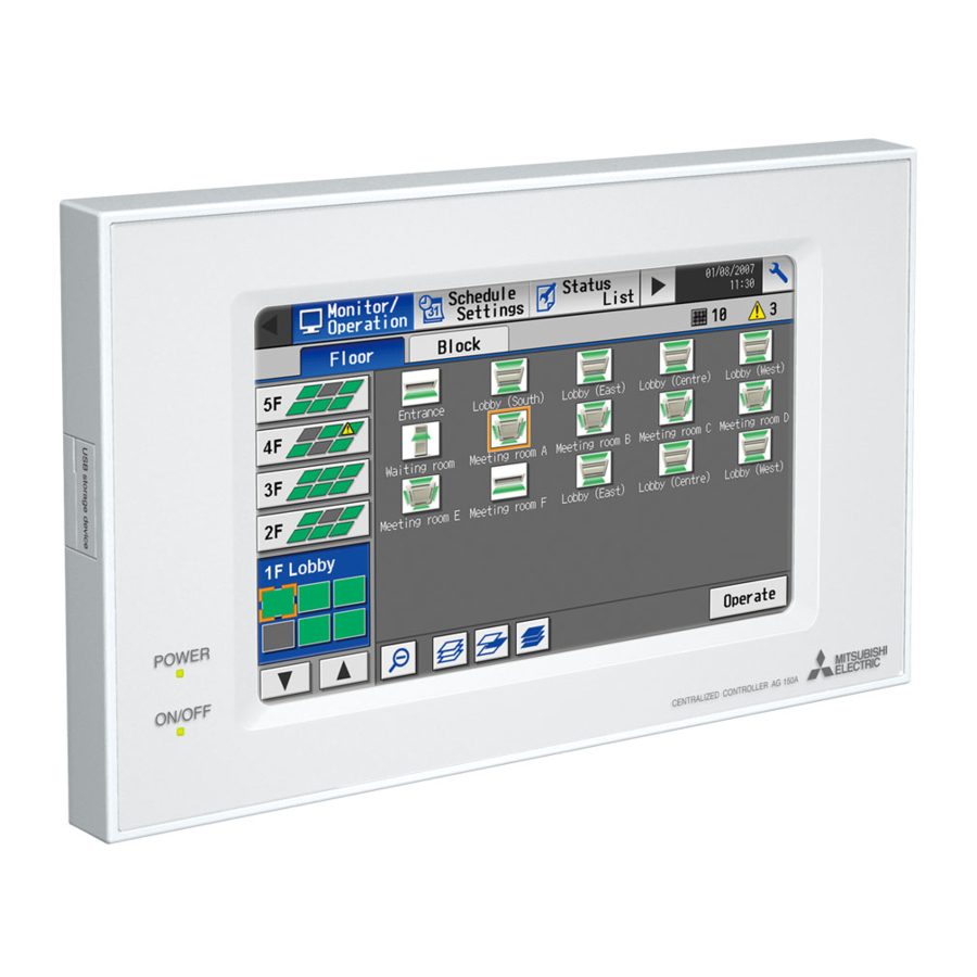
Centralized Controller
AG-150A
AG-150A-A
GB-50ADA-A
GB-50ADA-J
Before using the controller, please read this Instruction Book carefully to ensure proper operation.
Retain this manual for future reference.
(Web browser for System maintenance engineer)
Contents
1 Introduction ........................................................................... 2
1-1 Terms Used in This Manual.................................................... 2
1-2 Computer Requirements ........................................................ 2
control software (TG-2000A) .................................................. 2
2 Setting the Operating Environment ....................................... 3
2-1 Setting the PC IP Address...................................................... 3
2-2 Setting the Web Browser........................................................ 5
2-3 Setting the Java Execution Environment................................ 7
3 Performing Operations .......................................................... 8
3-1 Logging in on the AG-150A .................................................... 8
3-2 Checking the Operation Condition........................................ 12
3-3 Performing the Operations ................................................... 17
3-4 Checking the Measurement Condition ................................. 21
3-5 Checking the List of Malfunctioning Units............................. 24
3-7 Setting Schedules................................................................. 27
3-8 Checking the Malfunction Log .............................................. 41
3-9 Setting the Current Date and Time....................................... 42
3-10 Registering Users ............................................................... 43
3-11 Checking the Send Mail Log............................................... 45
3-12 Checking the Gas Amount.................................................. 46
4 Registering a License for Optional Functions ..................... 47
Instruction Book
WT05490X15
Ver. 3.00
Advertisement
Table of Contents

Subscribe to Our Youtube Channel
Related Manuals for Mitsubishi Electric AG-150A


Summary of Contents for Mitsubishi Electric AG-150A
-
Page 1: Table Of Contents
1 Introduction ................2 1-1 Terms Used in This Manual............ 2 1-2 Computer Requirements ............2 1-3 Notes on using AG-150A with the integrated centralized control software (TG-2000A) ..........2 2 Setting the Operating Environment ........3 2-1 Setting the PC IP Address............3 2-2 Setting the Web Browser............ -
Page 2: Introduction
(not applicable to GB-50ADA-A and GB-50ADA-J). Use this license key to use the initial setting browser, or in any other situations when a temporary license key “Web Monitor” is necessary. Note: Use a security device such as a VPN router when connecting the AG-150A to the Internet to prevent unauthorized access. -
Page 3: Setting The Operating Environment
Setting the PC IP Address Set an IP address on the PC that enables AG-150A to connect via a web browser. For instance, if the AG- 150A IP address is [192.168.1.1], the PC IP address will need to belong to the same system [192.168.1.101]. - Page 4 (4) In the [Internet Protocol (TCP/IP) Properties] dialog, click [Use the following IP address] and enter the IP address (for example, “192.168.1.101”) that you want to set in the IP address field. You normally set [255.255.255.0] as the subnet mask. Note: Ask your LAN administrator to provide the IP addresses and subnet mask.
-
Page 5: Setting The Web Browser
Setting the Web Browser Use a security device such as a VPN router when connecting the AG-150A to the Internet to prevent unauthorized access. If no security devices are installed, the operation settings may be changed by an unauthorized person without the knowledge of the user. - Page 6 Note: If connecting to more than one AG-150A, you can specify multiple IP addresses like [192.168.1.1; 192.168.1.2], however, it is also possible to use the asterisk (*) and specify [192.168.1*].
-
Page 7: Setting The Java Execution Environment
Setting the Java Execution Environment When using Java Plug-in version 1.6.0_10 or later, make the following environment settings (not required for version 1.6.0_09 or earlier). Note: The setting samples and screenshots used in this manual are those of Java Plug-in version 1.6.0_11. 2-3-1 Disabling the next-generation Java Plug-in (1) Open Java Control Panel by double-clicking Java in the Control Panel. -
Page 8: Performing Operations
Follow the directions given here when performing operations. Note: If the AG-150A is restarted due to a power interruption etc., wait until the screen on the AG-150A main unit displays the normal operation screen (it takes several minutes before the normal operation screen is displayed) before using a web browser to access the AG-150A. - Page 9 : http://[IP address of the AG-150A]/fr/administrator.html German : http://[IP address of the AG-150A]/de/administrator.html Italian : http://[IP address of the AG-150A]/it/administrator.html Japanese : http://[IP address of the AG-150A]/ja/administrator.html Portuguese : http://[IP address of the AG-150A]/pt/administrator.html Russian : http://[IP address of the AG-150A]/ru/administrator.html Spanish : http://[IP address of the AG-150A]/es/administrator.html...
- Page 10 AG-150A can encrypt communication data using HTTPS (SSL). When connecting the AG-150A to the LAN that can be accessed by the general public, it is recommended that the following settings be made so that the units are monitored and controlled on the encrypted Web page.
- Page 11 (4) If the security alert has not been disabled, after entering the web address and hitting the Enter (Return) key, a security alert message will alert asking if you want to proceed . This is because the AG-150A uses the self-authentication system. Click [Yes] and proceed.
-
Page 12: Checking The Operation Condition
Click the menu item [Monitor/Operation], or click [Condition List] in the sub menu to display a list of the operation condition of all the air conditioner, Ventilator (LOSSNAY), Air To Water (PWFY) groups, and general equipment. Layout of the selected floor can be displayed when floor layout setting is performed on AG-150A. (not applicable to GB-50ADA-A and GB-50ADA-J) This screen allows the operator to view a list of all the groups to monitor for malfunctions and prevent units being left on by mistake. - Page 13 Item Description When floor layout setting is performed on AG-150A (not applicable to GB-50ADA-A and GB- 50ADA-J), preset floors are selectable besides [Overview] . When a floor is selected, a window that shows group icons will be displayed on the floor layout.
- Page 14 Note: The energy saving icon is displayed while the energy-saving control is performed in a group of ventilator units. Note: When connecting multiple AG-150A controllers by connecting an Expansion Controller to the system, “Schedule set,” “Schedule Not Available,” and “Energy saving” will be displayed only on the AG-150A controller that is executing these functions.
- Page 15 3-2-2 Checking the operation condition of groups in different blocks Click [Block] in the Overview/Floor layout screen to display the operation condition of air conditioner, Ventilator (LOSSNAY), Air To Water (PWFY) groups, and general equipment for each block. Use this screen if you want to check data not included in the List screen such as operation mode and set temperature or if you want to check operation condition for each block.
- Page 16 Group icon Not Available initial startup) Note: When connecting multiple AG-150A controllers by connecting an Expansion Controller to the system, “Schedule set” and “Schedule Not Available” will be displayed only on the AG-150A controller that is executing this function. Group name display The group names are displayed.
-
Page 17: Performing The Operations
Performing the Operations Text below explains how to perform air conditioner, Ventilator (LOSSNAY), Air To Water (PWFY), or general equipment operations that target one group, one block, or all groups, and how to perform HWHP (CAHV) operations that target one group or all groups. 3-3-1 Performing the operations of air conditioners and various groups Text below explains how to perform air conditioner, Ventilator (LOSSNAY), Air To Water (PWFY), or general equipment operations that target one group, one block, or all groups. - Page 18 Item Description Click to adjust the air direction. (Mid3) (Mid 2) (Mid 1) (Mid 0) (Horizontal) (Swing) (Auto) Air direction Note: If it is a model that does not support air direction adjustment, this item is not displayed. Note: Available functions vary depending on the unit model. Click to adjust the fan speed.
- Page 19 3-3-1-2 Performing the operations that target one block (1) Select the block you want to operate as an entire block from the operation condition monitoring screen for block lists and click [Batch Operation]. When air conditioner groups, ventilator (LOSSNAY) groups, and general equipment groups exist together in the selected block, a new screen will appear to select the group.
- Page 20 3-3-2 Performing the operations of HWHP (CAHV) Text below explains how to perform HWHP (CAHV) operations that target one group or all groups. 3-3-2-1 Performing the operations that target one group When you click on a group icon in the operation condition monitoring screen that shows the list of all groups, the operation screen for that group will appear.
-
Page 21: Checking The Measurement Condition
Checking the Measurement Condition Text below explains how to check the measurement condition either by list or graph. Note: An AI controller (PAC-YG63MCA) and a commercially available temperature sensor and humidity sensor are required to measure the temperature and humidity. Note: A PI controller (PAC-YG60MCA) and a commercially available pulse output meter are required to measure the electric, water, heat, and gas consumptions. - Page 22 3-4-2 Using a graph Click [Trend Graph] on the measurement condition list screen, and select the measured item to be displayed. The measured value can be checked by graph. The graph can also be downloaded as a CSV file. Note: [Temperature], [Humidity], [Electric power for peak cut control], and [electric power] can be displayed in the trend graph. Overview display Click to display the measurement value as Update to most recent...
- Page 23 Item Description Click [Download] to download the graph in CSV format. The data format of the downloaded data is as follows. Item Format 121: Temperature data 122: Humidity data First line File type 123: Peak cut control data 125: Electric energy yyyy/mm/dd Second line Date...
-
Page 24: Checking The List Of Malfunctioning Units
Checking the List of Malfunctioning Units Click the menu item [Monitor/Operation] and then click the sub menu [Malfunction List]. A list of units that are currently malfunctioning appears. All reset Click to reset errors on all units as one batch operation. - Page 25 When an error is reset, units other than the ones in error may come to a stop. Types of units in error and the affected units that will stop Units in error Units that stop AG-150A (EC), GB-50ADA None Outdoor unit All indoor units that are connected to the outdoor unit in error...
-
Page 26: Checking The List Of Units With A Triggered Filter Sign
Checking the List of Units with a Triggered Filter Sign Click the menu item [Monitor/Operation] and click the sub menu [Filter Sign List]. A list of the units with a triggered filter sign appears. All reset Click to reset the filter sign on all units with triggered filter signs. -
Page 27: Setting Schedules
If a license has not been acquired, only the weekly schedule 1 functions available can be used. Note: The same schedule settings that are made via the Web browser can be made on the AG-150A LCD screen. Note: When connecting multiple AG-150A controllers by connecting an Expansion Controller to the system, schedule settings for the groups should be made only on one of the AG-150A controllers. - Page 28 It is possible to set different weekly/annual/today’s schedules for each air conditioner group. Moreover, for any weekly/annual/today’s schedule run for a particular day, the priority in which it is run will be from the highest and the order will be [Today’s], [Annual], [Weekly]. Group 1 August, 2008 Group 2...
- Page 29 3-7-1 Setting the Weekly Schedule Click the menu item [Schedule Settings] and click [Weekly 1], [Weekly 2], [Weekly 3], [Weekly 4] or [Weekly 5] in the sub menu to display the each Weekly Schedule setting screen. To set a weekly schedule, you first must select what will be the target of this schedule and then set the schedule details from Sunday right through to Saturday.
- Page 30 Select the name of the block that the group belongs to, and then select the group name in the Setting Object box. Alternatively it is possible to just select the group name and the group number. Once the group is selected, the contents of the schedule saved for that group will be displayed in the Contents of Schedule box.
- Page 31 (1-3)Select all groups When you want to set a schedule that will apply to all groups, select [All Group] in the Setting Range box. When air conditioner groups, ventilator (LOSSNAY) groups, Air To Water (PWFY) groups, and general equipment groups exist together in the system, a new screen will appear to select the group.
- Page 32 (4)Set the contents of the schedule When one of the [Edit] buttons in the Contents of Schedule box is clicked, a screen to set a schedule operation will appear. Use this screen to set when to run an operation and set the type of schedule operation (ON/OFF, operation mode, temperature setting, fan direction, fan speed, prohibit remote controller operation) and then press the [OK] button.
- Page 33 3-7-1-2 Setting the Weekly Schedule for HWHP (CAHV) group If a HWHP (CAHV) group has been registered, the [Air Conditioners] and [HWHP] buttons will appear as shown in the figure below. Click [HWHP] to access the window for setting the weekly schedule for HWHP (CAHV) units.
- Page 34 (1-2)Select all groups When you want to set a schedule that will apply to all groups, select [All Group] in the Setting Range box. Next a screen to select the schedule setup method will appear. Select either [New settings] or [Based on the following group settings]. If you plan to add to an existing setting, and then choose to base it on an existing setting and select the name of the group you want to base the setting on and click the [OK] button.
- Page 35 3-7-2 Setting an Annual Schedule Click the menu item [Schedule Settings] and click [Annual] in the sub menu to display the Annual Schedule setting screen. You can use the annual schedule to set schedules for days such as public holidays and summer vacation that need to be scheduled differently to the weekly schedule.
- Page 36 (3)Set the contents of the schedule setting When one of the [Edit] buttons in the Contents of Schedule box is clicked, a screen to set a schedule operation will appear. Use this screen to set when to run an operation and set the type of schedule operation (ON/OFF, operation mode, temperature setting,fan direction, fan speed, prohibit remote controller operation) and then press the [OK] button.
- Page 37 (6)Save the contents of schedule After you finished setting the contents of the schedule, save the schedule setting by clicking the [Save Settings] button. If the contents of the schedule setting have changed since the previous save, you can click the [Undo] button to restore the setting contents back to the saved settings.
- Page 38 (4)Specify the day(s) for pattern allocation Follow the same procedures as outlined in section 3-7-2-1(4). (5)Copy a schedule to another pattern or to another group Follow the same procedures as outlined in section 3-7-2-1(5). (6)Save the contents of schedule Follow the same procedures as outlined in section 3-7-2-1(6). 3-7-3 Modifying Today's Schedule Click the menu item [Schedule Settings], or click [Today] in the sub menu to display the Today’s Schedule setting screen.
- Page 39 order to reach the scheduled temperature at the scheduled time. (When the unit starts the first time after power reset, the operation starts 30 minutes before the scheduled time.) When using this function, also set the operation mode and setting temperature. If "Prohibit Remote Controller" is set at the same time, remote controller is prohibited at its setting time.
- Page 40 3-7-3-2 Modifying Today's Schedule for HWHP (CAHV) group If a HWHP (CAHV) group has been registered, the [Air Conditioners] and [HWHP] buttons will appear as shown in the figure below. Click [HWHP] to access the window for setting the today's schedule for HWHP (CAHV) units.
-
Page 41: Checking The Malfunction Log
Checking the Malfunction Log Click the menu item [Malfunction Log] to display a log of unit errors (the last 64 errors). Click the sub menu [Communication Error] to display, the M-NET communication error log. Note: If Expansion Controllers are connected, the latest 64 errors for each Expansion Controller system (EC1, EC2, or EC3) will appear. -
Page 42: Setting The Current Date And Time
Note: The clock setting made on the screen below will be reflected on the clocks on other units that are connected to the M-NET line, on the Expansion Controllers (PAC-YG50ECA), and on the AG-150A controller whose “Time master setting” is set to Sub (with someexceptions). -
Page 43: Registering Users
Please use this screen to add or modify a user name and password to login to the AG-150A, and to register a group that can be operated by a public user. If the groups that can be operated have been specified, when a public user logs in, that user will only be able to view and operate the groups that were specified. - Page 44 (1)Add or edit user information Click an [Edit] button in the User Information display to display the Expansion Controller system selection buttons screen for setting user information. Enter the user name, password and select the groups available to that user and click [OK]. Note: When a public user logs in, only the groups specified here will be available to that user.
-
Page 45: Checking The Send Mail Log
3-11 Checking the Send Mail Log Click the menu item [Maintenance] to display the log of mail sent when an error occurred and after error recovery. In order for a mail to be sent when an error occurs, the date related to sending the mail must be to set using Initial Setting Web. -
Page 46: Checking The Gas Amount
3-12 Checking the Gas Amount Click [Maintenance] on the menu and then [Gas Amount Check], a screen will appear that allows the user to check the gas amount. Use this option to check for refrigerant leak from the outdoor unit. Note: Those outdoor units that do not support the gas amount checking function via the remote command will not appear on this screen. -
Page 47: Registering A License For Optional Functions
"Web Monitor" is necessary. Note: When multiple AG-150A controllers are connected by connecting an Expansion Controller to the system, the license to use the optional functions is required only for the AG-150A controller on which the functions are actually used. - Page 48 [Modification list] Ver. Category Item Contents Page/Section Section 3-1-1 Increased Weekly Five types of weekly schedule patterns are available Section 3-7 Function schedule patterns instead of two. Section 3-7-1 Weekly schedule The Monitor/Operation screen was modified to display Section 3-2-1 Function number display the weekly schedule number that is currently effective.
- Page 52 This product is designed and intended for use in the residential, commercial and light-industrial environment. The product at hand is • Low Voltage Directive 2006/95/EC based on the following • Electromagnetic Compatibility Directive EU regulations: 2004/108/EC • Restriction of Hazardous Substances 2011/65/EU Please be sure to put the contact address/telephone number on this manual before handing it to the customer.
Need help?
Do you have a question about the AG-150A and is the answer not in the manual?
Questions and answers