
Related Manuals for Toro 22306


Summary of Contents for Toro 22306
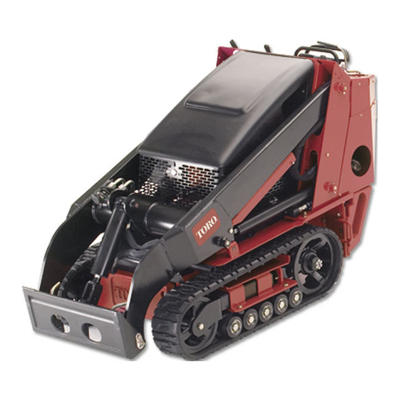
- Page 1 Form No. 3354-650 Rev B Dingo® TX 420 and TX 425 Compact Utility Loader Model No. 22306—Serial No. 260000001 and Up Model No. 22307—Serial No. 260000001 and Up Register your product at www.Toro.com Original Instructions (EN)
-
Page 2: Introduction
Warning Service Dealer or Toro Customer Service and have the model and serial numbers of your product CALIFORNIA ready. The model and serial numbers are stamped Proposition 65 Warning into a plate mounted under the hood near the belt drive. Write the numbers in the space provided. -
Page 3: Table Of Contents
Contents Drive System Maintenance......33 Servicing the Tracks......33 Controls System Maintenance....36 Introduction ............2 Adjusting the Traction Control Safety ..............4 Alignment ......37 Safe Operating Practices ...... 4 Adjusting the Traction Control Slope Chart ......... 8 Neutral Position ....37 Safety and Instructional Decals .... -
Page 4: Safety
Safety hearing protection. Long hair, loose clothing or jewelry may get tangled in moving parts. Improper use or maintenance by the operator • Inspect the area where the equipment is to be or owner can result in injury. To reduce used and remove all objects such as rocks, toys, the potential for injury, comply with these and wire which can be thrown by the machine. - Page 5 • Ensure that you operate the traction unit in traction unit. Tall grass can hide obstacles. areas where there are no obstacles in close • Use only Toro-approved attachments. proximity to the operator. Failure to maintain Attachments can change the stability and...
- Page 6 Make any necessary repairs before spark plug wires before making any repairs. restarting. Disconnect the negative terminal first and • Use only genuine Toro replacement parts to the positive last. Reconnect positive first and ensure that original standards are maintained. negative last.
- Page 7 hydraulic fluid. Use cardboard or paper to find hydraulic leaks; never use your hands. Hydraulic fluid escaping under pressure can penetrate skin and cause injury requiring surgery within a few hours by a qualified surgeon or gangrene may result.
-
Page 8: Slope Chart
Slope Chart... -
Page 9: Safety And Instructional Decals
Safety and Instructional Decals Safety decals and instructions are easily visible to the operator and are located near any area of potential danger. Replace any decal that is damaged or lost. 108-4658 2. Fast 1. Operator’s Manual location. 3. Slow 108-4674 108-5599... - Page 10 107-9309 1. Warning—read the Operator’s Manual for information on charging the battery; contains lead; do not discard. 2. Read the Operator’s Manual. HYDRAULIC COUPLERS HYDRAULIC COUPLERS HYDRAULIC COUPLERS HYDRAULIC COUPLERS HYDRAULIC COUPLERS HYDRAULIC COUPLERS HYDRAULIC COUPLERS HYDRAULIC COUPLERS HYDRAULIC COUPLERS HYDRAULIC COUPLERS HYDRAULIC COUPLERS HYDRAULIC COUPLERS...
- Page 11 108-4670 108-4671 93-9084 1. Lift point 2. Tie-down point...
-
Page 12: Setup
Setup Charging the battery produces gasses Step that can explode. Never smoke near the battery and keep sparks and flames away from battery. 3. When the battery is fully charged, unplug Charging the Battery the charger from the electrical outlet, then disconnect the charger leads from the battery No Parts Required posts (Figure 2). -
Page 13: Product Overview
Product Overview Figure 3 1. Track 5. Loader arms 9. Mount plate 13. Fuel tank 2. Track adjustment chamber 6. Hood 10. Tie-down/lift loop 14. Reverse safety plate 3. Lift cylinder 7. Auxiliary hydraulic couplers 11. Control panel 4. Cylinder lock 8. - Page 14 Traction Control To move forward, move the traction control forward. To move rearward, move the traction control rearward (Figure 5). To turn, rotate the traction control in the desired direction (Figure 5). The farther you move the traction control in any direction, the faster the traction unit will move in that direction.
-
Page 15: Parking Brake Lever
Parking Brake Lever procedures based on a 100, 200, or 400 hour schedule. These reminders come on starting three To set the parking brake, push the brake lever hours prior to the service interval time and flash forward and to the left and then pull it rearward at regular intervals for six hours. -
Page 16: Specifications
66 inches (168 cm) Attachments/Accessories A selection of Toro approved attachments and accessories are available for use with the machine to enhance and expand its capabilities. Contact your Authorized Service Dealer or Distributor or go to www.Toro.com for a list of all approved attachments and accessories. -
Page 17: Stability Data
205 slope, rearward up a 125 slope, or sideways on a 145 slope, as listed in the following table for the TX 420 traction unit. TX 420, Model 22306 Maximum Recommended Slope when Operating with:... -
Page 18: Operation
Operation In certain conditions during fueling, static Note: Determine the left and right sides of the electricity can be released causing a spark machine from the normal operating position. which can ignite the gasoline vapors. A fire Important: Before operating, check the or explosion from gasoline can burn you and fuel and oil level, and remove debris from the others and can damage property. -
Page 19: Checking The Engine Oil Level
Note: A fuel stabilizer/conditioner is most effective when mixed with fresh gasoline. To minimize the chance of varnish deposits in the fuel system, use fuel stabilizer at all times. Filling the Fuel Tank 1. Park the traction unit on a level surface, lower the loader arms, and stop the engine. -
Page 20: Starting And Stopping The
Important: If the engine is run at high speeds when the hydraulic system is cold (i.e., when the ambient air temperature is near freezing or lower), hydraulic system damage could occur. When starting the engine in cold conditions, allow the engine to run in the middle throttle position for 2 to 5 minutes before moving the throttle to fast (rabbit). -
Page 21: Using The Cylinder Lock
2. Open the rear access cover. 3. Using a wrench, turn the tow valves on the hydraulic pumps twice counter-clockwise (Figure 12). Figure 13 1. Cylinder lock 3. Clevis pin 2. Lift cylinder 4. Hairpin cotter 5. Lower the cylinder lock over the cylinder rod and secure it with the clevis pin and hairpin cotter (Figure 13). -
Page 22: Using Attachments
Check the Installing an Attachment receiver plate and clean it if necessary. Important: Use only Toro-approved attachments. Attachments can change the stability and the operating characteristics of the traction unit. The warranty of the traction unit may be voided if used with unapproved attachments. -
Page 23: Securing The Traction Unit For Transport
Connecting the Hydraulic Hoses 8. Confirm that the connection is secure by pulling on the hoses. If the attachment requires hydraulics for operation, 9. Move the auxiliary hydraulics lever to neutral. connect the hydraulic hoses as follows: 1. Stop the engine. Removing an Attachment 2. -
Page 24: Maintenance
Maintenance Note: Determine the left and right sides of the machine from the normal operating position. Recommended Maintenance Schedule(s) Maintenance Service Maintenance Procedure Interval After the rst 8 operating • Replace the hydraulic lter. hours • Change the engine oil. After the rst 50 •... -
Page 25: Premaintenance Procedures
If you leave the key in the ignition switch, someone could accidently start the engine and seriously injure you or other bystanders. Remove the key from the ignition and disconnect the wire from the spark plug before you do any maintenance. Set the wire aside so that it does not accidentally contact the spark plug. Premaintenance Procedures Before opening any of the covers, stop the engine... -
Page 26: Closing The Rear Access Cover
Installing the Side Screens Slide the side screens into place in the slots in the front screen and frame. Removing the Front Screen If the engine has been running the heat shield will be very hot and could burn you. Figure 18 1. -
Page 27: Lubrication
11. Tighten the bolts securing the front weight (Figure 20). 12. Install the side screens and close the hood. Lubrication Greasing the Traction Unit Grease all pivot joints every 8 operating hours and immediately after every washing. Grease Type: General-purpose grease. 1. -
Page 28: Engine Maintenance
Figure 24 4. Pump grease into the fittings until grease begins to ooze out of the bearings (approximately 3 pumps). Figure 25 5. Wipe up any excess grease. 1. Knob 6. Foam pre-lter 2. Air cleaner cover 7. Paper lter Engine Maintenance 3. -
Page 29: Servicing The Engine Oil
5. Lightly tap the paper filter on a flat surface to Crankcase Capacity: w/filter, 2.1 qt. (2 l) remove dust and dirt (Figure 27). Viscosity: See table below Figure 27 1. Paper element 2. Rubber seal Figure 28 6. Inspect the paper filter for tears, an oily film, and damage to the rubber seal. -
Page 30: Servicing The Spark Plugs
5. When the oil has drained completely, replace 7. Install the replacement oil filter to the filter the plug. adapter. Turn the oil filter clockwise until the rubber gasket contacts the filter adapter, then Note: Dispose of the used oil at a certified tighten the filter an additional 1/2 turn. -
Page 31: Fuel System Maintenance
Important: Never clean the spark plugs. Always replace the spark plugs when they have a black coating, worn electrodes, an oily film, or cracks. Figure 33 1. Filter 2. Hose clamp 5. Squeeze the ends of the hose clamps together Figure 32 and slide them away from the filter (Figure 33). -
Page 32: Electrical System Maintenance
1. Lower the loader arms, stop the engine, and remove the key. 2. Syphon the gasoline from the tank using a pump type syphon. Note: Now is the best time to install a new fuel filter because the fuel tank is empty. Electrical System Maintenance G003794... -
Page 33: Drive System Maintenance
Important: Do not overfill the battery disconnect the charger leads from the battery because electrolyte (sulfuric acid) can posts (Figure 35). cause severe corrosion and damage to the 5. Replace the battery cover. chassis. Drive System 5. Wait five to ten minutes after filling the battery cells. - Page 34 6. Lower the traction unit to the ground. tension using the following procedure: Replacing the Tracks (TX 420, Model 22306) When the tracks are badly worn, replace them. 1. Lower the loader arms, stop the engine, and remove the key.
- Page 35 7. When the track is off of the tension wheel, remove it from the drive sprocket and road wheels (Figure 39). 8. Beginning at the drive sprocket, coil the new track around the sprocket, ensuring that the lugs on the track fit between the spacers on the sprocket (Figure 39).
-
Page 36: Controls System Maintenance
16. Torque the nut to 300 ft-lb (407 N⋅m). 17. Turn the tensioning screw counter-clockwise until the distance between the tension nut and the back of the tension tube (Figure 37) is 2-3/4 inches (7 cm). 18. Align the closest notch in the tension screw to the locking bolt hole and secure the screw with the locking bolt and nut. -
Page 37: Alignment
Adjusting the Traction Control Alignment If the traction control bar does not rest flush and square with the reference bar when in the full backward position, immediately complete the following procedure: 1. Park the traction unit on a flat surface and Figure 45 lower the loader arm. -
Page 38: Hydraulic System Maintenance
When the traction unit is running, you could be caught and injured in moving parts or burned on hot surfaces. Stay away from pinch points, moving parts, and hot surfaces when adjusting the running traction unit. 5. If the left track moves, lengthen or shorten the right traction rod until the track stops moving. -
Page 39: Changing The Hydraulic Fluid
Changing the Hydraulic Fluid Change the hydraulic fluid after every 400 operating hours or yearly. 1. Position the traction unit on a level surface. 2. Open the hood. 3. Install the cylinder lock, stop the engine, and remove the key. 4. -
Page 40: Cleaning
Hydraulic fluid escaping under pressure can penetrate skin and cause injury. Fluid injected into the skin must be surgically removed within a few hours by a doctor familiar with this form of injury or gangrene may result. • Keep your body and hands away from pin hole leaks or nozzles that eject high pressure hydraulic fluid. -
Page 41: Cleaning The Chassis
Cleaning the Chassis Over time, the chassis under the engine collects dirt and debris that must be removed. Using a flashlight, open the hood and inspect the area under the engine on a regular basis. When the debris is 1 to 2 inches deep, complete the following procedure (refer to Figure 51 throughout this procedure): Figure 52... - Page 42 Important: The fuel line and wires must be away from the engine pulleys and the frame. 21. Replace the rear panel and secure it with the six bolts and nuts removed previously (Figure 51). 22. Secure the battery tray with the bolts and washers removed previously.
-
Page 43: Storage
Storage B. Run the engine to distribute conditioned fuel through the fuel system (5 minutes). 1. Lower the loader arms, stop the engine, and C. Stop the engine, allow it to cool and drain remove the key. the fuel tank using a pump type syphon. 2. -
Page 44: Troubleshooting
Troubleshooting Problem Possible Cause Corrective Action The starter does not crank 1. The battery is 1. Charge the battery or discharged. replace it. 2. The electrical 2. Check the electrical connections are connections for good corroded or loose. contact. 3. The relay or switch is 3. - Page 45 Problem Possible Cause Corrective Action The engine overheats. 1. The engine load is 1. Reduce ground speed. excessive. 2. The oil level in crankcase 2. Check and add oil to the is low. crankcase. 3. The cooling ns and 3. Remove any obstructions air passages under the from the cooling ns and engine blower housing...
-
Page 46: Schematics
Schematics Electrical Schematic (Rev. A) - Page 47 Hydraulic Schematic (Rev. A)
- Page 51 The use of any add-on or modied parts will be grounds for disallowing a warranty claim made in accordance with this article. The Toro® Company will not be liable under this Article to warrant failures of warranted parts caused by the use of an add-on or modied part.
- Page 52 (Dealer) to obtain guarantee policies for your country, province, or state. If for any reason you are dissatised with your Distributor’s service or have difculty obtaining guarantee information, contact the Toro importer. If all other remedies fail, you may contact us at Toro Warranty Company.