Table of Contents
Advertisement
Advertisement
Table of Contents

Related Manuals for Cisco 575 LRE CPE

Summary of Contents for Cisco 575 LRE CPE
- Page 1 Cisco 575 LRE CPE Hardware Installation Guide April 2001 Corporate Headquarters Cisco Systems, Inc. 170 West Tasman Drive San Jose, CA 95134-1706 http://www.cisco.com Tel: 408 526-4000 800 553-NETS (6387) Fax: 408 526-4100 Customer Order Number: DOC-7811469= Text Part Number: 78-11469-01...
- Page 2 You can determine whether your equipment is causing interference by turning it off. If the interference stops, it was probably caused by the Cisco equipment or one of its peripheral devices. If the equipment causes interference to radio or television reception, try to correct the interference by using one or more of the following measures: •...
- Page 3 Enterprise/Solver, EtherChannel, EtherSwitch, FastHub, FastSwitch, IOS, IP/TV, LightStream, MICA, Network Registrar, Post-Routing, Pre-Routing, Registrar, StrataView Plus, Stratm, SwitchProbe, TeleRouter, and VCO are registered trademarks of Cisco Systems, Inc. or its affiliates in the U.S. and certain other countries. All other brands, names, or trademarks mentioned in this document or Web site are the property of their respective owners. The use of the word partner does not imply a partnership relationship between Cisco and any other company.
-
Page 5: Table Of Contents
Cisco Documentation CD-ROM Ordering Documentation Documentation Feedback Obtaining Technical Assistance Cisco.com Technical Assistance Center xvii Contacting TAC by Using the Cisco TAC Website xvii Contacting TAC by Telephone xvii Overview C H A P T E R Features Front-Panel Description... - Page 6 A P P E N D I X Connector and Cable Specifications A P P E N D I X Connector Specifications ENET Port WALL Port PHONE Port Cable Specifications Straight-Through Cable Pinouts Cisco 575 LRE CPE Hardware Installation Guide 78-11469-01...
- Page 7 Jewelry Removal Warning Main Disconnecting Device Overtemperature Warning Power Warning Circuit Breaker (15A) Warning Voltage Warning C-11 Lightning Activity Warning C-13 Product Disposal Warning C-14 No On/Off Switch Warning C-15 SELV Circuit Warning C-16 Cisco 575 LRE CPE Hardware Installation Guide 78-11469-01...
- Page 8 Contents Cisco 575 LRE CPE Hardware Installation Guide viii 78-11469-01...
-
Page 9: Preface
Ethernet and local area networking. Purpose The Cisco 575 LRE CPE Hardware Installation Guide documents the hardware features of the CPE. The guide describes the physical and performance characteristics of the CPE, explains how to install a CPE, and provides troubleshooting information and specifications. -
Page 10: Organization
Terminal sessions and system displays are in font. • screen • Information you enter is in font. boldface screen • Nonprinting characters, such as passwords or tabs, are in angle brackets (< >). Cisco 575 LRE CPE Hardware Installation Guide 78-11469-01... - Page 11 (Voor vertalingen van de waarschuwingen die in deze publicatie verschijnen, kunt u het aanhangsel C “Translated Safety Warnings” (Vertalingen van veiligheidsvoorschriften) raadplegen.) Cisco 575 LRE CPE Hardware Installation Guide 78-11469-01...
- Page 12 La traduzione delle avvertenze riportate in questa pubblicazione si trova nell’appendice C, “Translated Safety Warnings” (Traduzione delle avvertenze di sicurezza). Cisco 575 LRE CPE Hardware Installation Guide 78-11469-01...
- Page 13 (Se förklaringar av de varningar som förekommer i denna publikation i appendix C "Translated Safety Warnings" [Översatta säkerhetsvarningar].) Cisco 575 LRE CPE Hardware Installation Guide xiii 78-11469-01...
-
Page 14: Related Publications
Related Publications Related Publications You can order printed copies of documents with a DOC-xxxxxx= number. For more information about the Cisco 575 LRE and related products, refer to the following publications: • Catalyst 2900 Series XL Hardware Installation Guide (order number DOC-786461=) •... -
Page 15: Cisco Documentation Cd-Rom
408 526-7208 or, in North America, by calling 800 553-NETS(6387). Documentation Feedback If you are reading Cisco product documentation on the World Wide Web, you can send us your comments by completing the online survey. When you display the document listing for this platform, click Give Us Your Feedback. If you are using the product-specific CD and you are connected to the Internet, click the pencil-and-paper icon in the toolbar to display the survey. -
Page 16: Obtaining Technical Assistance
This highly integrated Internet application is a powerful, easy-to-use tool for doing business with Cisco. Cisco.com provides a broad range of features and services to help customers and partners streamline business processes and improve productivity. Through Cisco.com, you can find information about Cisco and our networking solutions,... -
Page 17: Technical Assistance Center
P4—You need information or assistance on Cisco product capabilities, • product installation, or basic product configuration. In each of the above cases, use the Cisco TAC website to quickly find answers to your questions. To register for Cisco.com, go to the following website: http://www.cisco.com/register/... - Page 18 P1—Your production network is down, causing a critical impact to business • operations if service is not restored quickly. No workaround is available. P2—Your production network is severely degraded, affecting significant • aspects of your business operations. No workaround is available. Cisco 575 LRE CPE Hardware Installation Guide xviii 78-11469-01...
-
Page 19: Overview
Rear-panel description Features The Cisco 575 LRE CPE, hereafter referred to as the CPE, is based on very-high-data-rate digital subscriber line (VDSL) technology. The CPE connects a computer or laptop to a Catalyst 2912 XL LRE or 2924 LRE XL switch at distances of up to 4921 feet (1500 meters) by using Long-Reach Ethernet technology over ordinary telephone lines. - Page 20 In a typical installation, CPEs are installed in rooms of a multidwelling tenant building. The CPE data rates and profile settings are controlled by a Catalyst 2912 LRE XL or 2924 LRE XL switch. Figure 1-1 shows a typical LRE installation. Cisco 575 LRE CPE Hardware Installation Guide 78-11469-01...
- Page 21 For installations where telephone services will be routed to a PBX switch, you can install a Cisco LRE POTS Splitter (PS-1M-LRE-48). For more information about this POTS splitter, refer to the Installation Notes for the Cisco LRE 48 POTS Splitter.
-
Page 22: Front-Panel Description
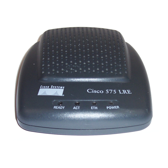
LEDs and their meanings. Figure 1-2 Front-Panel of the CPE Table 1-1 CPE Front Panel LEDs Function READY LRE link to base switch OK Ethernet activity Ethernet link OK POWER Power indicator Cisco 575 LRE CPE Hardware Installation Guide 78-11469-01... -
Page 23: Rear-Panel Description
Connector Label Connector Description Power connector ENET RJ-45 connector for the Ethernet port on your PC or laptop WALL RJ-11 connector for the telephone wall jack PHONE RJ-11 connector for a telephone Cisco 575 LRE CPE Hardware Installation Guide 78-11469-01... - Page 24 Chapter 1 Overview Rear-Panel Description Cisco 575 LRE CPE Hardware Installation Guide 78-11469-01...
-
Page 25: Installation
C H A P T E R Installation This chapter describes how to install your Cisco 575 LRE CPE and interpret the LEDs to ensure proper operation. Read the topics, and perform these procedures in the order that they are presented: Pre-installation information and guidelines •... -
Page 26: Preparing For Installation
Before working on equipment that is connected to power lines, remove Warning jewelry (including rings, necklaces, and watches). Metal objects will heat up when connected to power and ground and can cause serious burns or weld the metal object to the terminals. Cisco 575 LRE CPE Hardware Installation Guide 78-11469-01... - Page 27 Ultimate disposal of this product should be handled according to all national Warning laws and regulations. Warning Unplug the power cord before you work on a system that does not have an on/off switch. Cisco 575 LRE CPE Hardware Installation Guide 78-11469-01...
-
Page 28: Emc Regulatory Statements
U.S. regulatory information for this product is in the front matter of this manual. Taiwan Package Contents When you unpack the CPE, be sure that the package contains the items in the following list. If any items are missing, notify your authorized Cisco sales representative: • Cisco 575 LRE CPE AC power cord and adapter •... -
Page 29: Installing The Cpe On A Desk
The CPE is sold individually or in multipackages of six and twenty-four. The Note multipackages include only one hardware installation guide, the release notes, and the Cisco Information Packet for every six CPEs. Installing the CPE On a Desk Locate the adhesive strip with the rubber feet in the CPE mounting-kit. - Page 30 Allow a minimum of three inches (7.6 centimeters) between the rear Note of the desk and the screw template so that there is enough room for the cables to clear the wall. (See Figure 2-1.) Cisco 575 LRE CPE Hardware Installation Guide 78-11469-01...
- Page 31 Remove the screw template from underneath the desk. Step 8 Slide the CPE onto the mounting screws until it locks in place. (See Figure 2-2.) Step 9 Cisco 575 LRE CPE Hardware Installation Guide 78-11469-01...
-
Page 32: Installing The Cpe On A Wall
Tips the CPE before mounting it on wall because the connectors might be hidden from view after the CPE is installed. For more information, see the connection procedures beginning on page 12. Cisco 575 LRE CPE Hardware Installation Guide 78-11469-01... - Page 33 Position the screw template so that the two side-by-side slots are facing away from the floor. (See Figure 2-3.) This ensures the cables will face towards the floor after they are connected. Note Do not attach the screw template to the wall yet. Cisco 575 LRE CPE Hardware Installation Guide 78-11469-01...
- Page 34 Step 8 Remove the screw template from the wall. Slide the CPE onto the screws until it locks in place. (See Figure 2-4.) Step 9 Cisco 575 LRE CPE Hardware Installation Guide 2-10 78-11469-01...
- Page 35 Chapter 2 Installation Installing the CPE On a Wall Figure 2-4 Installing the CPE On a Wall CPE slides on this way Screw Screw Cisco 575 LRE CPE Hardware Installation Guide 2-11 78-11469-01...
-
Page 36: Connecting To A Pc Or Laptop
PC or jack power laptop Connect the other end of the Ethernet cable to the RJ-45 connector of the Ethernet Step 2 card in your PC or laptop. (See Figure 2-6.) Cisco 575 LRE CPE Hardware Installation Guide 2-12 78-11469-01... - Page 37 If this is the case, connect one end of the Ethernet cable to the CPE and leave the other end of the Ethernet cable on top of the desk. (See Figure 2-7.) Cisco 575 LRE CPE Hardware Installation Guide 2-13 78-11469-01...
-
Page 38: Connecting To A Wall-Mounted Telephone Jack
Figure 2-5.) Note Use a standard telephone cord with RJ-11 connectors on both ends. Step 2 Connect the other end of the telephone cord to the telephone jack in the wall. Cisco 575 LRE CPE Hardware Installation Guide 2-14 78-11469-01... -
Page 39: Connecting To A Telephone
They also prevent nonfiltered telephone rings or nonfiltered telephone transitions (such as on-hook to off-hook) from interrupting the LRE connection. For more information about microfilters, contact your Cisco sales representative. Connecting the Power Cord Connect the power cord to the power connector on the CPE rear panel. -
Page 40: Attaching The Cable Lock
To install the cable lock, follow these steps: Locate the cable lock in the accessory kit. Step 1 Step 2 Slide the cable lock onto the CPE until it clicks in place. (See Figure 2-9 Figure 2-10.) Cisco 575 LRE CPE Hardware Installation Guide 2-16 78-11469-01... - Page 41 Chapter 2 Installation Attaching the Cable Lock Figure 2-9 Attaching the Cable Lock Cable lock Figure 2-10 Cable Lock Installed on CPE (Side View) To electric outlet Cable lock Cisco 575 LRE CPE Hardware Installation Guide 2-17 78-11469-01...
- Page 42 CPE if it is mounted onto a desktop. Simply slide the cable lock into the CPE and snap it into place. Figure 2-11 Securing the Cable Lock with Mounting Screw Screw Cable lock Cisco 575 LRE CPE Hardware Installation Guide 2-18 78-11469-01...
-
Page 43: Powering On The Cpe
CPE configuration, data speed settings, and monitoring are controlled from a Catalyst 2912 LRE XL or Catalyst 2924 LRE XL switch. Refer to the Catalyst 2900 Series XL and Catalyst 3500 Series XL Software Configuration Guide for additional information. Cisco 575 LRE CPE Hardware Installation Guide 2-19 78-11469-01... - Page 44 Chapter 2 Installation Where to Go Next Cisco 575 LRE CPE Hardware Installation Guide 2-20 78-11469-01...
-
Page 45: Troubleshooting
For more information, refer to the Catalyst 2900 Series XL and Catalyst 3500 Series XL Software Configuration Guide. Table 3-1 lists the CPE problems that you might encounter and their solutions. Cisco 575 LRE CPE Hardware Installation Guide 78-11469-01... - Page 46 Repair the cable trunking or select an alternative pair. CPE is not communicating with, or Verify switch and upstream might be attempting to exceed the network status. bandwidth selected by, the Catalyst 2900 LRE XL switch. Cisco 575 LRE CPE Hardware Installation Guide 78-11469-01...
- Page 47 “Straight-Through Cable Pinouts” section on page B-3. • The Ethernet cable is wired incorrectly or is defective. Replace with a tested good • cable. Data service unavailable. Verify switch and upstream network status. Cisco 575 LRE CPE Hardware Installation Guide 78-11469-01...
- Page 48 Chapter 3 Troubleshooting Cisco 575 LRE CPE Hardware Installation Guide 78-11469-01...
-
Page 49: Appendix
A P P E N D I X Technical Specifications Table A-1 lists the technical specifications for the Cisco 575 LRE CPE, and Table A-2 lists the agency approvals for EMI and safety. Table A-1 Technical Specifications for the Cisco 575 LRE CPE... - Page 50 FCC Part 15 Class B No. 950 IEC 950/EN 60950 EN 55022 Class B (CISPR 22 Class B) AS/NZS 3260, TS001 VCCI Class B AS/NZS 3548 Class B BCIQ CCIB/CCEE CCIB/CCEE NOM019-1988 Cisco 575 LRE CPE Hardware Installation Guide 78-11469-01...
-
Page 51: Appendix
The ENET port is a 10/100 port that uses an RJ-45 connector with Ethernet pinouts. The ENET port has the transmit (TD) and receive (RD) signals internally crossed so that a straight-through cable (included) can be attached to the port. Figure B-2 shows the pinouts. Cisco 575 LRE CPE Hardware Installation Guide 78-11469-01... -
Page 52: Wall Port
Figure B-3 for the connector pinouts. Figure B-3 RJ-11 WALL Port Connector Pinouts Label 1 2 3 4 5 6 Pass-through 1 Pass-through 2 LRE tip LRE ring Pass-through 5 Pass-through 6 Cisco 575 LRE CPE Hardware Installation Guide 78-11469-01... -
Page 53: Phone Port
1 2 3 4 5 6 Pass-through 1 Pass-through 2 Phone tip Phone ring Pass-through 5 Pass-through 6 Cable Specifications Straight-Through Cable Pinouts The schematics of the straight-through cable are shown in Figure B-5. Cisco 575 LRE CPE Hardware Installation Guide 78-11469-01... - Page 54 Appendix B Connector and Cable Specifications Cable Specifications Figure B-5 Straight-Through Cable Pinouts Switch Switch 3 TD+ 3 RD+ 6 TD– 6 RD– 1 RD+ 1 TD+ 2 RD– 2 TD– Cisco 575 LRE CPE Hardware Installation Guide 78-11469-01...
-
Page 55: Appendix
A P P E N D I X Translated Safety Warnings This appendix repeats in multiple languages the warnings in this guide. Cisco 575 LRE CPE Hardware Installation Guide 78-11469-01... -
Page 56: Qualified Personnel Warning
¡Atención! Estos equipos deben ser instalados y reemplazados exclusivamente por personal técnico adecuadamente preparado y capacitado. Varning Denna utrustning ska endast installeras och bytas ut av utbildad och kvalificerad personal. Cisco 575 LRE CPE Hardware Installation Guide 78-11469-01... -
Page 57: Installation Warning
Leia as instruções de instalação antes de ligar o sistema à sua fonte de energia. ¡Advertencia! Ver las instrucciones de instalación antes de conectar el sistema a la red de alimentación. Varning! Läs installationsanvisningarna innan du kopplar systemet till dess strömförsörjningsenhet. Cisco 575 LRE CPE Hardware Installation Guide 78-11469-01... -
Page 58: Jewelry Removal Warning
Schmuck (einschließlich Ringe, Ketten und Uhren) abnehmen. Metallgegenstände erhitzen sich, wenn sie an das Netz und die Erde angeschlossen werden, und können schwere Verbrennungen verursachen oder an die Anschlußklemmen angeschweißt werden. Cisco 575 LRE CPE Hardware Installation Guide 78-11469-01... - Page 59 är kopplad till kraftledningar. Metallobjekt hettas upp när de kopplas ihop med ström och jord och kan förorsaka allvarliga brännskador; metallobjekt kan också sammansvetsas med kontakterna. Cisco 575 LRE CPE Hardware Installation Guide 78-11469-01...
-
Page 60: Main Disconnecting Device
El conjunto de clavija y toma ha de encontrarse siempre accesible ya que hace las veces de dispositivo de desconexión principal. Varning! Man måste alltid kunna komma åt stickproppen i uttaget, eftersom denna koppling utgör den huvudsakliga frånkopplingsanordningen. Cisco 575 LRE CPE Hardware Installation Guide 78-11469-01... -
Page 61: Overtemperature Warning
40°C. Aviso Para evitar o sobreaquecimento do sistema, não o utilize em áreas que excedam a temperatura ambiente máxima recomendada de 40°C (104°F). Cisco 575 LRE CPE Hardware Installation Guide 78-11469-01... -
Page 62: Power Warning
Il dispositivo è stato progettato per l’uso con sistemi di alimentazione TN. Advarsel Utstyret er utfomet til bruk med TN-strømsystemer. Aviso O dispositivo foi criado para operar com sistemas de corrente TN. Cisco 575 LRE CPE Hardware Installation Guide 78-11469-01... -
Page 63: Circuit Breaker (15A) Warning
(surtension), ce produit dépend de l'installation électrique du local. Vérifier qu'un fusible ou qu'un disjoncteur de 120 V alt., 15 A U.S. maximum (240 V alt., 16 A international) est utilisé sur les conducteurs de phase (conducteurs de charge). Cisco 575 LRE CPE Hardware Installation Guide 78-11469-01... - Page 64 Denna produkt är beroende av i byggnaden installerat kortslutningsskydd (överströmsskydd). Kontrollera att säkring eller överspänningsskydd används på fasledarna (samtliga strömförande ledare) för internationellt bruk max. 240 V växelström, 16 A (i USA max. 120 V växelström, 15 A). Cisco 575 LRE CPE Hardware Installation Guide C-10 78-11469-01...
-
Page 65: Voltage Warning
Bei nicht übereinstimmender Spannung kann es zu Geräteschäden und Feuergefahr kommen. Wenn die auf dem Etikett angegebene Spannung nicht mit der Steckdosenspannung übereinstimmt, schließen Sie das Gerät nicht an diese Steckdose an. Cisco 575 LRE CPE Hardware Installation Guide C-11 78-11469-01... - Page 66 Varning Inkompatibla spänningar kan resultera i materiella skador samt utgör brandfara. Om den spänning som anges på etiketten skiljer sig från strömuttagets spänning ska chassit inte anslutas till detta uttag. Cisco 575 LRE CPE Hardware Installation Guide C-12 78-11469-01...
-
Page 67: Lightning Activity Warning
No operar el sistema ni conectar o desconectar cables durante el transcurso de descargas eléctricas en la atmósfera. Varning! Vid åska skall du aldrig utföra arbete på systemet eller ansluta eller koppla loss kablar. Cisco 575 LRE CPE Hardware Installation Guide C-13 78-11469-01... -
Page 68: Product Disposal Warning
Deitar fora este produto em conformidade com todas as leis e regulamentos nacionais. Al deshacerse por completo de este producto debe seguir todas ¡Advertencia! las leyes y reglamentos nacionales. Varning! Vid deponering hanteras produkten enligt gällande lagar och bestämmelser. Cisco 575 LRE CPE Hardware Installation Guide C-14 78-11469-01... -
Page 69: No On/Off Switch Warning
Antes de trabajar sobre cualquier sistema que carezca de ¡Advertencia! interruptor de Encendido/Apagado (ON/OFF), desenchufar el cable de alimentación. Varning! Dra ur nätsladden innan du utför arbete på ett system utan strömbrytare. Cisco 575 LRE CPE Hardware Installation Guide C-15 78-11469-01... -
Page 70: Selv Circuit Warning
SELV-circuits niet op telefoonnetwerkvoltage-circuits (TNV) worden aangesloten. Hoewel ENET-poorten gebruik maken van RJ-45-aansluitingen waarin RJ-11-telefoonstekkers passen, mogen TNV-circuits niet op een ENET-poort worden aangesloten. Wees voorzichtig tijdens het aansluiten van kabels. Cisco 575 LRE CPE Hardware Installation Guide C-16 78-11469-01... - Page 71 SELV-Schaltungen nicht an TNV-Schaltungen anschließen. Die ENET-Anschlüsse verwenden zwar RJ-45-Steckverbindungen, die RJ-11- Telefoniestecker akzeptieren, jedoch dürfen TNV-Schaltungen nicht mit den ENET-Anschlüssen verbunden werden. Beim Anschließen der Kabel mit Vorsicht vorgehen. Cisco 575 LRE CPE Hardware Installation Guide C-17 78-11469-01...
- Page 72 (TNV). Embora as portas ENET utilizem conectores RJ-45 que aceitarão fichas telefónicas do tipo RJ-11, os circuitos TNV não devem ser ligados às portas ENET. Tenha o devido cuidado ao ligar os cabos. Cisco 575 LRE CPE Hardware Installation Guide C-18 78-11469-01...
- Page 73 SELV-kretsar med telefonnätspänning (TNV). Även om ENET-portarna använder RJ-45 kontakter som accepterar RJ-11 telefonikontakter behöver inte telefonnätspänning (TNV) vara uppkopplad till ENET-portarna. Var försiktig när du kopplar ihop kablarna. Cisco 575 LRE CPE Hardware Installation Guide C-19 78-11469-01...
- Page 74 Appendix C Translated Safety Warnings SELV Circuit Warning Cisco 575 LRE CPE Hardware Installation Guide C-20 78-11469-01...