
Related Manuals for Honeywell 7866


Summary of Contents for Honeywell 7866
- Page 1 7866 Triple Range Digital H and CO Analyzer/Indicator and Gas Sampling Panel Operation and Maintenance Manual 70-82-25-110 9/06 Industrial Measurement and Control...
- Page 2 Contact your local sales office for warranty information. If warranted goods are returned to Honeywell during the period of coverage, Honeywell will repair or replace without charge those items it finds defective. The foregoing is Buyer's sole remedy and is in lieu of all other warranties, expressed or implied, including those of merchantability and fitness for a particular purpose.
- Page 3 This manual describes the installation and operation of the 7866 Triple Range Digital H and CO Analyzer/Indicator and Gas Sampling Panel and its digital controller. Contacts World Wide Web The following lists Honeywell’s World Wide Web sites that will be of interest to our customers. Honeywell Organization WWW Address (URL) Corporate http://www.honeywell.com Industrial Measurement and Control http://www.honeywell.com/imc...
- Page 4 Regular checks as part of routine inspections or establishing from the material data sheets that it is resistant to specific chemicals. 9. A copy of the certification marking can be found on page v of this manual and Honeywell drawing 51452210.
- Page 5 Copy of the certification marking 9/06 7866 Triple Range Digital H and CO Analyzer/Indicator - Operation and Maintenance...
- Page 6 Chassis Ground. Identifies a connection to the chassis or frame of the equipment shall be bonded to Protective Earth at the source of supply in accordance with national and local electrical code requirements. 7866 Triple Range Digital H and CO Analyzer/Indicator - Operation and Maintenance...
-
Page 7: Table Of Contents
Overview ............................19 Sensing Unit Requirements and Location ..................19 Mounting the Sensing Unit......................20 Piping or Tubing Connections...................... 20 Mounting the 7866 Digital Controller/Indicator ................23 Electrical Considerations......................26 Wiring Between Sensing Unit, Controller, and Indicator ............27 Checklist............................32 SET UP MODE.................... - Page 8 Overview ............................47 Sensing Unit Calibration Warning ....................47 7866 Analyzer Input Calibration ....................48 7866 Remote Indicator Input Calibration..................51 Restoring Factory-set Input Calibration ..................52 Output Calibration ........................53 Security Lockout .......................... 54 Setting the Alarm Limits ......................56 OPERATION .......................
- Page 9 Table 8-2 Binary Count Sequence for Coarse Zero Jumper Pattern ............68 Table 8-3 Coarse-Zero Jumper Pattern ...................... 69 Table 8-4 Troubleshooting Procedures ...................... 70 Table 9-1 Replaceable Parts for 7872 Gas Sampling Panel............... 78 9/06 7866 Triple Range Digital H and CO Analyzer/Indicator - Operation and Maintenance...
- Page 10 Figure 1-1 Digital 7866 Analyzer ........................ 1 Figure 1-2 Sensing Unit, Showing Removal of Entire Sensing Assembly..........3 Figure 1-3 7866 Digital Controller, Front View ..................5 Figure 1-4 Triple-Range Hydrogen and Carbon Dioxide Analyzer Controller and Display Logic Chart... 6 Figure 1-5 Screen capture of Process Instrument Explorer running on a Pocket PC........
-
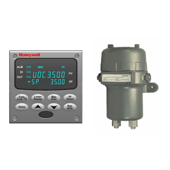
Page 11: Introduction
(receiver)—both shown in Figure 1-1—and a power supply. The sensing unit is located at the sampling site; the 7866 Digital Controller is arranged for panel mounting in a non-hazardous area. The sensing unit receives a continuous flow of the binary or multi-component gas mixture, measures the concentration of the sample gas and transmits an electrical signal to the control unit. -
Page 12: Sensing Unit
Introduction Sensing Unit The 7866 Thermal Conductivity analyzer’s Sensor Assembly is supplied in an explosion proof housing. The housing consists of a rugged cast aluminum construction that permits reliable operation under adverse ambient conditions. The Sensor Assembly consists of two sections—the cell block assembly and the electronic assembly (Figure 1-2). -
Page 13: Figure 1-2 Sensing Unit, Showing Removal Of Entire Sensing Assembly
Inlet and outlet ports for sample gas Inlet and outlet ports for sample gas Figure 1-2 Sensing Unit, Showing Removal of Entire Sensing Assembly 9/06 7866 Triple Range Digital H and CO Analyzer/Indicator - Operation and Maintenance... -
Page 14: 7866 Digital Controller
90 Vac to 264 Vac or 24 Vac/dc. The line frequency can be 50 hertz or 60 hertz. Power for the 7866 Sensing Unit is supplied by a separate 30 Volt dc power supply. This power supply is also utilized by the controller to power its interconnections with the sensing unit. -
Page 15: Table 1-1 Function Of Keys
Configuration mode – Group or function prompt Figure 1-3 7866 Digital Controller, Front View Table 1-1 Function of Keys Function • Places the controller in the Configuration Set Up group select mode. Sequentially displays Set... -
Page 16: Figure 1-4 Triple-Range Hydrogen And Carbon Dioxide Analyzer Controller And Display Logic Chart
R3 SPAN = Range 3 Span 75% H 75% H (25% N (25% N (25% N (25% N Figure 1-4 Triple-Range Hydrogen and Carbon Dioxide Analyzer Controller and Display Logic Chart 7866 Triple Range Digital H and CO Analyzer/Indicator - Operation and Maintenance 9/06... -
Page 17: Principles Of Operation
Table 1-2 Relative Thermal Conductivity of Common Gases Component Thermal Conductivity (K) Component Thermal Conductivity (K) 1.000 0.342 1.028 0.350 1.040 0.540 1.450 0.665 5.530 0.704 6.803 0.771 0.958 0.989 9/06 7866 Triple Range Digital H and CO Analyzer/Indicator - Operation and Maintenance... -
Page 18: Process Instrument Explorer Software
Create/edit configurations live, just connect software to the controller via a communications port. • Create/edit configurations offline and download to controller later via a communications port. • Communication types available on every 7866: Infrared (optional) RS 485 (optional) Ethernet (optional) •... -
Page 19: Figure 1-6 Depiction Of Infrared Communications
You can now communicate. After 4 minutes, the port will be shut down again. Each controller may also be assigned a different communications address. Figure 1-6 Depiction of infrared communications 9/06 7866 Triple Range Digital H and CO Analyzer/Indicator - Operation and Maintenance... -
Page 20: Ce Conformity (Europe)
WARNING If this equipment is used in a manner not specified by the manufacturer, the protection provided by the equipment may be impaired. 7866 Triple Range Digital H and CO Analyzer/Indicator - Operation and Maintenance 9/06... -
Page 21: Specifications And Model Selection Guide
One range, as specified. For standard ranges, see Selection Guide Table in the Model Selection Guide. Explosion Proof Applications When measuring flammable gas mixture that contains oxygen, the maximum oxygen concentration must not exceed 21%. 9/06 7866 Triple Range Digital H and CO Analyzer/Indicator - Operation and Maintenance... - Page 22 Reference gas inlet and outlet: 1/4” OD tubing (compression fittings supplied) Electrical power inlet: Opening for 1/2” conduit (control unit only) Sensing unit power inlet (24 Vdc from control unit): 1/2” NPT (female conduit) 7866 Triple Range Digital H and CO Analyzer/Indicator - Operation and Maintenance...
- Page 23 Infrared Communications (Standard) Type: Serial Infrared (SIR) Length of Link: 3 ft. (1 m) maximum for IrDA 1.0 compliant devices Baud Rate: 19,200 or 38,400 baud selectable 9/06 7866 Triple Range Digital H and CO Analyzer/Indicator - Operation and Maintenance...
- Page 24 Group 1, Class A, ISM Equipment (EN55011, emissions), Industrial Equipment (EN61326, immunity) Method of EMC Technical File (TF) Assessment: Declaration of 51453681 Conformity: Miscellaneous Analyzer temperature: Sensing unit thermostated at 50 °C (122 °F) 7866 Triple Range Digital H and CO Analyzer/Indicator - Operation and Maintenance 9/06...
-
Page 25: Model Selection Guide
_ _ _ _ _ _ KEY NUMBER Selection Availability 7866 Digital Thermal Conductivity Analyzer for Hydrogen 07866DHH2 Cooled Generator Applications consisting of: a) 07866DHS2 Sensor Assembly (includes housing) b) 07866DHC2 Digital Control Unit 7866 Replacement Digital Control Unit Only... - Page 26 Input Voltage 210 -250VAC, 47-520 Hz DIN Adaptor Plate 30755223-002 Note 1: Warning - When measuring a gas mixture that contains oxygen, the maximum oxygen concentration must not exceed 21%. 7866 Triple Range Digital H and CO Analyzer/Indicator - Operation and Maintenance 9/06...
- Page 27 Specifications and Model Selection Guide Refer to Appendix A for ordering information on the optional 7872 Gas Sampling Panel. 9/06 7866 Triple Range Digital H and CO Analyzer/Indicator - Operation and Maintenance...
- Page 28 Specifications and Model Selection Guide 7866 Triple Range Digital H and CO Analyzer/Indicator - Operation and Maintenance 9/06...
-
Page 29: Installation
Installation 3. Installation Overview This section describes the installation requirements and procedures for the 7866 Triple Range Digital Analyzer/Indicator. Sensing Unit Requirements and Location Location Locate the sensing unit as close as possible to the sampling probe to minimize response lag. This should be at a point in the gas stream which best represents the true gas composition. -
Page 30: Mounting The Sensing Unit
Rotameter-type flowmeter) can be used in this line. If a longer vent line is required, use larger diameter tubing, e.g., 12 mm (1/2”) O.D. Refer to Appendix A for sampling and venting information. 7866 Triple Range Digital H and CO... - Page 31 If a good seal does not result, remove the compression nut and slide it onto the tubing, take out the small O-ring and slip it on the tubing, then assemble the fitting. 9/06 7866 Triple Range Digital H and CO Analyzer/Indicator - Operation and Maintenance...
-
Page 32: Figure 3-1 Outline And Mounting Dimensions For Sensing Unit
5.51 1. Weight of unit is approximately 18-3/4 lb. (8.5 kg) 2. Wiring diagram is ID-2071-356. Front View Figure 3-1 Outline and Mounting Dimensions for Sensing Unit 7866 Triple Range Digital H and CO Analyzer/Indicator - Operation and Maintenance 9/06... -
Page 33: Mounting The 7866 Digital Controller/Indicator
Conformity with these standards requires the user to provide adequate protection against a shock hazard. The user shall install this controller in an enclosure that limits OPERATOR access to the rear terminals. If the controller is used in a manner not specified by Honeywell, the protection provided by the equipment may be impaired. -
Page 34: Figure 3-2 Mounting Dimensions (Not To Scale)
Before mounting the controller, refer to the nameplate on the outside of the case and make a note of the model number. It will help later when selecting the proper wiring configuration. 7866 Triple Range Digital H and CO Analyzer/Indicator - Operation and Maintenance... -
Page 35: Table 3-1 Mounting Procedure
(Figure 3-3). Push the point of the screw through the center piercing the elastomeric material and then tighten screws to 5 lb-in (56 N•cm). 9/06 7866 Triple Range Digital H and CO Analyzer/Indicator - Operation and Maintenance... -
Page 36: Electrical Considerations
Appropriate suppression devices are commercially available. ATTENTION For additional noise information, refer to document number 51-52-05-01, How to Apply Digital Instrumentation in Severe Electrical Noise Environments. 7866 Triple Range Digital H and CO Analyzer/Indicator - Operation and Maintenance 9/06... -
Page 37: Wiring Between Sensing Unit, Controller, And Indicator
Make certain fully qualified personnel make this installation and all local regulations are observed. Failure to comply with these instructions could result in fire caused by explosion inside the housing. 9/06 7866 Triple Range Digital H and CO Analyzer/Indicator - Operation and Maintenance... -
Page 38: Figure 3-4 Mains Power Supply
Applying 90-264 Vac to an instrument rated for 24 Vac/dc will severely damage the instrument and is a fire and smoke hazard. damage the instrument and is a fire and smoke hazard. Figure 3-4 Mains Power Supply 7866 Triple Range Digital H and CO Analyzer/Indicator - Operation and Maintenance 9/06... -
Page 39: Figure 3-5 Interconnections Between Sensing Unit, Controller, And Indicator
Wiring Connections at the Digital Controller The output signal from the 7866 Digital Controller can be configured as a 4-20 milliampere signal or a 0- 20 milliampere signal. This signal is used to drive a recording device or to report to a DCS or PLC. The signal will proportionately reflect the percentage of measured gas. -
Page 40: Figure 3-6 Rs-422/485 Communications Option Connections
Use only Category 5 (STP CAT5) shielded twisted-pair Ethernet cables. For strain relief, secure your Ethernet cable to the controller with the tie wraps included in the kit using the holes in the bottom controller flange. 7866 Triple Range Digital H and CO Analyzer/Indicator - Operation and Maintenance... -
Page 41: Table 3-3 Terminals For Connecting A Udc To A Mdi Compliant Hub Or Switch Utilizing A Cross-Over Cable
Shield Position 24 RXD- TXD- Position 25 RXD+ TXD+ Position 26 TXD- RXD- Position 27 TXD+ RXD+ Use only Category 5 (STP CAT5) shielded twisted-pair Ethernet cables. 9/06 7866 Triple Range Digital H and CO Analyzer/Indicator - Operation and Maintenance... -
Page 42: Checklist
The meter should be wired in series with the signal wire between terminal 12 of the sensing unit and terminal 26 of the 7866 Digital Controller. The test meter used, whether for voltage or current output, should be a digital voltmeter or a millivolt potentiometer for best accuracy. -
Page 43: Set Up Mode
Set Up Mode 4. Set Up Mode Overview This section describes the steps to configure the 7866 Controller/Indicator for your application. Configuration Tips Introduction Table 4-1 lists some tips that will help you enter data more quickly. Table 4-1 Configuration Tips... -
Page 44: Unit Set Up Group
100%. PWR FREQ Input Frequency Selection 60 HZ 60 HZ 50 HZ DECIMAL Decimal Point Location XXX.X – One decimal place XXX.X XX.XX – Two decimal places 7866 Triple Range Digital H and CO Analyzer/Indicator - Operation and Maintenance 9/06... -
Page 45: Table 4-3 Indicator Unit Group Function Prompts
75-100%, or 100 - 75%. Input Frequency Selection 60 HZ 60 HZ PWR FREQ 50 HZ DECIMAL Decimal Point Location XXX.X – One decimal place XXX.X XX.XX – Two decimal places 9/06 7866 Triple Range Digital H and CO Analyzer/Indicator - Operation and Maintenance... -
Page 46: Alarms Set Up Group
ETHERNET—Enables Ethernet communications port. Appears only when a communication board is installed. ATTENTION The PIE Tool will not be able to communicate via this port if it is disabled. 7866 Triple Range Digital H and CO Analyzer/Indicator - Operation and Maintenance 9/06... - Page 47 TX DELAY—Configurable response-delay timer allows you to force the instrument to delay its response for a time period of from 1 to 500 milliseconds compatible with the host system hardware/software. 9/06 7866 Triple Range Digital H and CO Analyzer/Indicator - Operation and Maintenance...
- Page 48 Loopback test transmits on the RS-485 bus. The host computer should not be transmitting on the link while the Loopback test is active. 7866 Triple Range Digital H and CO Analyzer/Indicator - Operation and Maintenance 9/06...
-
Page 49: Calibration Group
(Lower Display) (Upper Display) Software Version VERSION 7866_n The first number set (7866) details the unit class as the 7866 product and the next number set gives the software version. RAM TEST Status of RAM test performed in PASS or FAIL background If status was FAIL, cycle power to see if error clears. -
Page 50: Figure 4-1 Ethernet Configuration Screen
This controller may be configured to support up to two Emails. Each Email can be sent to a different address. Emails are sent only when the selected alarm transitions from the OFF to the ON state. 7866 Triple Range Digital H and CO... -
Page 51: Figure 4-2 Email Configuration Screen
If the SMTP address on your network is changed, such as can happen when a server is replaced, then you must reconfigure the Email SMTP IP address in this instrument to match. 9/06 7866 Triple Range Digital H and CO Analyzer/Indicator - Operation and Maintenance... -
Page 52: Configuring Your Ethernet Connection
Select “PC COMM Setup”, then select “Infrared”. You cannot configure your Pocket PC for Ethernet. Figure 4-3 IR Communications Address Close the IR configuration window and then single click on the “Online Configuration” button. 7866 Triple Range Digital H and CO Analyzer/Indicator - Operation and Maintenance... -
Page 53: Figure 4-4 Configuration Upload In Progress
Section 4.8. Once you have changed the Ethernet settings and downloaded them to your controller, you will now be able to communicate with it via Ethernet. 9/06 7866 Triple Range Digital H and CO Analyzer/Indicator - Operation and Maintenance... -
Page 54: Connecting To The Controller Via Ethernet Communications
Once you have made an Ethernet connection between your PC and the controller, then change the Local Area Network (LAN) settings on your PC to be as follows: IP Address: 10.0.0.3 Subnet Mask: 255.255.255.0 Default Gateway: 10.0.0.1 7866 Triple Range Digital H and CO Analyzer/Indicator - Operation and Maintenance 9/06... -
Page 55: Figure 4-5 Ethernet Communications Address
“PC Comm Setup”. Now configure your “Communication Type” to Ethernet and your Ethernet address to 10.0.0.2 as shown in Figure 4-5. Figure 4-5 Ethernet Communications Address 9/06 7866 Triple Range Digital H and CO Analyzer/Indicator - Operation and Maintenance... -
Page 56: Figure 4-6 Configuration Upload In Progress
On some PCs and LANs, it is possible to simply allow the PC to get these settings automatically via the DHCP server. Contact your Information Technologies (IT) representative to see if this is available on your PC. 7866 Triple Range Digital H and CO Analyzer/Indicator - Operation and Maintenance... -
Page 57: Calibration
; 25 % N Indicator calibration The 7866 Indicator is calibrated at the factory before shipping. You do not need to recalibrate it before operating it. The PV Input selection is factory set for 1-5V to be consistent with the Analyzer output of 4-20mA. If you change the analyzer output to 0-20 mA you must change the PV Input to 0-5V. -
Page 58: 7866 Analyzer Input Calibration
If, after the Zero or Span "live" value has stabilized, no change is made, you should still perform the same key-press sequences. For example, if in Step 5 you make no change to the displayed value, continue to Step 7 by pressing the FUNCTION key twice. 7866 Triple Range Digital H and CO Analyzer/Indicator - Operation and Maintenance... -
Page 59: Table 5-2 Input Calibration For Range 2
If, after the Zero or Span "live" value has stabilized, no change is made, you should still perform the same key-press sequences. For example, if in Step 5 you make no change to the displayed value, continue to Step 7 by pressing the FUNCTION key twice. 9/06 7866 Triple Range Digital H and CO Analyzer/Indicator - Operation and Maintenance... -
Page 60: Table 5-3 Input Calibration For Range 3
If, after the Zero or Span "live" value has stabilized, no change is made, you should still perform the same key-press sequences. For example, if in Step 5 you make no change to the displayed value, continue to Step 7 by pressing the FUNCTION key twice. 7866 Triple Range Digital H and CO Analyzer/Indicator - Operation and Maintenance... -
Page 61: 7866 Remote Indicator Input Calibration
Calibration 7866 Remote Indicator Input Calibration Disconnect the PV Input terminals from the Analyzer output and connect them to a voltage milliampere source. For zero and span enter values which are consistent with the PV Input selection (1-5 volts or 0-5 volts). -
Page 62: Restoring Factory-Set Input Calibration
You will see: Upper Display: DISABL (default selection) Lower Display: PVINPUT Select RESTOR to restore factory calibration for desired Range input parameters. Saves data to the factory-set values. FUNCTION 7866 Triple Range Digital H and CO Analyzer/Indicator - Operation and Maintenance 9/06... -
Page 63: Output Calibration
The output range of the current output used to transmit ranging data to the Indicator is fixed at 4-20 mA and is not changeable in the field. 9/06 7866 Triple Range Digital H and CO Analyzer/Indicator - Operation and Maintenance... -
Page 64: Security Lockout
Calibration Security Lockout Introduction The LOCKOUT feature in the 7866 Controller inhibits changes to certain functions or parameters by unauthorized personnel. There are three different lockout levels: NONE Allows changes to all functions and parameters. CALIB Calibration group functions are hidden from view. -
Page 65: Table 5-9 Changing Security Level
If the security code is unknown, see Appendix B – Security Bypass. FUNCTION You will see LOCKOUT in the Lower Display. Select NONE. FUNCTION Saves selection to nonvolatile memory. 9/06 7866 Triple Range Digital H and CO Analyzer/Indicator - Operation and Maintenance... -
Page 66: Setting The Alarm Limits
Calibration Setting the Alarm Limits Each 7866 Digital Controller/Indicator can be supplied with two alarms and two alarm relay outputs as a standard. (Second alarm is mutually exclusive with 4-20 mA ranging output.) The alarms are set to operate in Range 3 only. The intention of the alarms is to detect the loss of Hydrogen for the sealed system. The assumption is that the lost Hydrogen will be replaced with atmospheric air. -
Page 67: Table 5-10 Alarm Adjustment Procedure
If you have forgotten the password, see Appendix B for the Security Bypass Procedure. Alarm Limits may be adjusted while the 7866 Digital Controller is operating. Care should be taken to minimize the effects of entering out-of-range values. - Page 68 Calibration 7866 Triple Range Digital H and CO Analyzer/Indicator - Operation and Maintenance 9/06...
-
Page 69: Operation
This section describes operating guidelines and procedures for the 7866 Digital Analyzer. Operating Notes All three range readings are displayed in the upper display of the 7866 digital controller/indicator. To select the measured value of a particular range, the operator selects the desired range (1, 2, or 3) by pressing the LOWER DISPLAY key on the instrument’s face. - Page 70 If the reading at the output device is not correct, adjust zero and span, using zero and span gases, in accordance with the procedures as described in Section 5.3 7866 Analyzer Input Calibration. If only a slight zero-gas error exists, it can be corrected without rechecking the span gas.
-
Page 71: Maintenance
IMPROPER SENSING UNIT DISASSEMBLY • Never open the 7866 Sensing Unit case until the line power has been disconnected at the 7866 Digital Controller. • Always loosen the set screw provided on this model before turning the top threaded cover. -
Page 72: Figure 7-1 Sensing Unit Mother And Daughter Circuit Cards Parts List
Maintenance Figure 7-1 Sensing Unit Mother and Daughter Circuit Cards Parts List 7866 Triple Range Digital H and CO Analyzer/Indicator - Operation and Maintenance 9/06... -
Page 73: Table 7-1 Sensing Unit Cell Assembly Cable Connections
The large outside O-ring can be removed from the fitting and the three filter elements can be pushed through the flame arrestor body from outside the casting with a length of tubing. 9/06 7866 Triple Range Digital H and CO Analyzer/Indicator - Operation and Maintenance... -
Page 74: Repacking
When repacking for shipment, seal the sensor assembly inlet and outlet ports with tape to prevent packing material from clogging these ports. Figure 7-2 Gas Inlet and Outlet Fitting Parts 7866 Triple Range Digital H and CO Analyzer/Indicator - Operation and Maintenance... -
Page 75: Spare Parts
O-ring for Explosion-proof Housing Cap 31082103 Thermistor detectors (matched pair) 31130135 Plastic washer seals (for above detectors) 31301420 Resistor pair for Heater Assembly 31411258 Heater control Thermistor 31353402 9/06 7866 Triple Range Digital H and CO Analyzer/Indicator - Operation and Maintenance... - Page 76 Maintenance 7866 Triple Range Digital H and CO Analyzer/Indicator - Operation and Maintenance 9/06...
-
Page 77: Troubleshooting
Do not open, even when isolated, when a flammable/dust atmosphere is present. SENSING UNIT WITH EXPLOSION-PROOF DESIGN • Never open the threaded cover until the power line is disconnected at the 7866 Digital Controller. • Always loosen the set screw before turning the threaded cover. -
Page 78: Table 8-1 Coarse Zero Adjustment
010011 100011 110011 000100 010100 100100 110100 000101 010101 100101 110101 000110 010110 100110 110110 000111 010111 100111 110111 001000 011000 101000 111000 001001 011001 101001 111001 7866 Triple Range Digital H and CO Analyzer/Indicator - Operation and Maintenance 9/06... -
Page 79: Fault Isolation Tests
7866 Digital Controller. The troubleshooting table can be used to better identify the malfunction, either before or after these isolation tests are performed, according to the specific symptom. -
Page 80: Table 8-4 Troubleshooting Procedures
1a. Check for correct voltage at terminals L1/H and L2/N. 1b. Replace the display. 2. Cannot adjust for zero 2a. ZERO adjuster in 7866 Digital 2a. Adjust coarse ZERO in sensing unit in signal with “zero” gas. Controller is out of adjusting accordance with the Coarse Zero Adjustment. - Page 81 5d. Remove measuring detector, inspect for detector. cracks in glass or loose dirt in cell. 5e. Faulty detector bridge-current 5e. Replace sensing-unit printed circuit card regulator. assembly.**** 9/06 7866 Triple Range Digital H and CO Analyzer/Indicator - Operation and Maintenance...
- Page 82 ****Temperature regulator is a high-frequency variable-duty cycle controller and field repair is not recommended. Replace the entire sensing-unit card and return the faulty unit to the factory for repairs. 7866 Triple Range Digital H and CO Analyzer/Indicator - Operation and Maintenance...
-
Page 83: Additional Troubleshooting
25 °C, 77 °F, R = 5000 ohms ± 20% Measuring and reference cells resistances should be matched to 1 %. Test for short circuit between leads of each of the above components and case ground. 9/06 7866 Triple Range Digital H and CO Analyzer/Indicator - Operation and Maintenance... - Page 84 Troubleshooting 7866 Triple Range Digital H and CO Analyzer/Indicator - Operation and Maintenance 9/06...
-
Page 85: Appendix A - 7872 Gas Sampling Panel
Constructions TABLE II - SAMPLE MOISTURE CONTENT For Sampling Dry Sources TABLE III - ANALYZER COMPATIBILITY For Use with 7866 Analyzer TABLE IV - TAGGING OPTIONS None Linen Tag - Up to 15 Characters on 3 Lines Stainless Steel Tag - Up to 22 Characters on 3 Lines... -
Page 86: Installation
Before adjusting the Ref. Air Regulator or Sample Regulator, unlock the adjustment knob by pulling up on the yellow lock ring. After adjustment is made, push down on the lock ring to maintain the setting. For 7866 explosion-proof applications, set regulator pressure no higher than 2 psig The four-way selector valve is used to select from ZERO gas, SPAN gas or SAMPLE gas inlets. -
Page 87: Figure 9-1 7872 Gas Sampling Panel Mounting Dimensions
Appendix A 7872 Gas Sampling Panel Figure 9-1 7872 Gas Sampling Panel Mounting Dimensions 9/06 7866 Triple Range Digital H and CO Analyzer/Indicator - Operation and Maintenance... -
Page 88: Maintenance
Ref Air Regulator (includes Filter cartridge) 51451417-501 Sample Regulator (includes filter cartridge) 51500283-501 Gas Inlet and Vent Bulkhead Union Connectors 31076870 Bypass Flowmeter 31072935 Bypass Valve (5 psig) 31072926 Flowmeter 31072925 7866 Triple Range Digital H and CO Analyzer/Indicator - Operation and Maintenance 9/06... -
Page 89: Appendix B - Security Bypass
Your controller has a security bypass code. Secured areas cannot be accessed without the use of the Operator or Master codes. If you have forgotten or misplaced the access code, you can enter the factory default code, “7866”. Use the procedure given in Table 5-8 to enter 7866 to override the forgotten code. 9/06... - Page 90 Appendix B Security Bypass 7866 Triple Range Digital H and CO Analyzer/Indicator - Operation and Maintenance 9/06...
-
Page 91: Sales And Service
CANADA ITALY REPUBLIC OF SWITZERLAND SINGAPORE HONEYWELL LIMITED HONEYWELL S.p.A. HONEYWELL A.G. HONEYWELL PTE LTD THE HONEYWELL Via P. Gobetti, 2/b Hertistrasse 2 ARGENTINA CENTRE BLOCK 750E CHAI 20063 Cernusco Sul 8304 WALLISELLEN HONEYWELL S.A.I.C. - Page 92 Industrial Measurement and Control Honeywell 1100 Virginia Drive Fort Washington, PA 19034 www.honeywell.com/imc 70-82-25-110 Rev. D 09 06 Printed in USA...