Sign In
Upload
Manuals
Brands
Honeywell Manuals
Measuring Instruments
7866
Honeywell 7866 Manuals
Manuals and User Guides for Honeywell 7866. We have
1
Honeywell 7866 manual available for free PDF download: Operation And Maintenance Manual
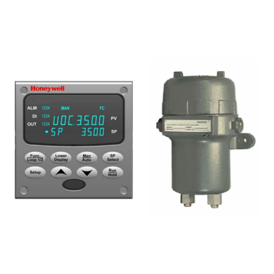
Honeywell 7866 Operation And Maintenance Manual (92 pages)
Triple Range Digital H2 and CO2 Analyzer/Indicator and Gas Sampling Panel
Brand:
Honeywell
| Category:
Measuring Instruments
| Size: 1.28 MB
Table of Contents
Table of Contents
7
Introduction
11
Overview
11
Figure 1-1 Digital 7866 Analyzer
11
Sensing Unit
12
Figure 1-2 Sensing Unit, Showing Removal of Entire Sensing Assembly
13
7866 Digital Controller
14
Table 1-1 Function of Keys
15
Figure 1-3 7866 Digital Controller, Front View
15
Figure 1-4 Triple-Range Hydrogen and Carbon Dioxide Analyzer Controller and Display Logic Chart
16
Principles of Operation
17
Table 1-2 Relative Thermal Conductivity of Common Gases
17
Process Instrument Explorer Software
18
Figure 1-5 Screen Capture of Process Instrument Explorer Running on a Pocket PC
18
Figure 1-6 Depiction of Infrared Communications
19
CE Conformity (Europe)
20
Specifications and Model Selection Guide
21
Specifications
21
Model Selection Guide
25
Installation
29
Overview
29
Sensing Unit Requirements and Location
29
Mounting the Sensing Unit
30
Piping or Tubing Connections
30
Figure 3-1 Outline and Mounting Dimensions for Sensing Unit
32
Mounting the 7866 Digital Controller/Indicator
33
Figure 3-2 Mounting Dimensions (Not to Scale)
34
Table 3-1 Mounting Procedure
35
Figure 3-3 Mounting Methods
35
Electrical Considerations
36
Wiring between Sensing Unit, Controller, and Indicator
37
Table 3-2 Permissible Wiring Bundling
37
Figure 3-4 Mains Power Supply
38
Figure 3-5 Interconnections between Sensing Unit, Controller, and Indicator
39
Figure 3-6 RS-422/485 Communications Option Connections
40
Figure 3-7 Ethernet Communications Option with Adaptor Board
40
Table 3-3 Terminals for Connecting a UDC to a MDI Compliant Hub or Switch Utilizing a Cross-Over Cable
41
Table 3-4 Terminals for Connecting a UDC Directly to a PC Utilizing a Straight-Through Cable
41
Figure 3-8 Ethernet Communications Option Without Adaptor Board
41
Checklist
42
Set up Mode
43
Overview
43
Configuration Tips
43
Table 4-1 Configuration Tips
43
Unit Set up Group
44
Table 4-2 Controller Unit Group Function Prompts
44
Table 4-3 Indicator Unit Group Function Prompts
45
Alarms Set up Group
46
Communications Set up Group
46
Table 4-4 Alarms Group Function Prompts
46
Table 4-5 Communications Group Function Prompts
46
Calibration Group
49
Status Group
49
Tool Ethernet and Email Configuration Screens
49
Table 4-6 Status Group Function Prompts
49
Figure 4-1 Ethernet Configuration Screen
50
Figure 4-2 Email Configuration Screen
51
Configuring Your Ethernet Connection
52
Connecting to the Controller Via Infrared Communications
52
Figure 4-3 IR Communications Address
52
Figure 4-4 Configuration Upload in Progress
53
Connecting to the Controller Via Ethernet Communications
54
Figure 4-5 Ethernet Communications Address
55
Figure 4-6 Configuration Upload in Progress
56
Calibration
57
Overview
57
Sensing Unit Calibration Warning
57
7866 Analyzer Input Calibration
58
Table 5-1 Input Calibration for Range 1
58
Table 5-2 Input Calibration for Range 2
59
Table 5-3 Input Calibration for Range 3
60
7866 Remote Indicator Input Calibration
61
Table 5-4 PV Input Calibration
61
Restoring Factory-Set Input Calibration
62
Table 5-5 Restoring Analyzer's Factory-Set Input Calibration Values
62
Table 5-6 Restoring Indicator's Factory-Set Input Calibration Values
62
Output Calibration
63
Table 5-7 Output Calibration Procedure
63
Security Lockout
64
Table 5-8 Entering the Security Code
64
Table 5-9 Changing Security Level
65
Setting the Alarm Limits
66
Table 5-10 Alarm Adjustment Procedure
67
Operation
69
Overview
69
Operating Notes
69
Maintenance
71
Routine Maintenance
71
Parts Replacement
71
Sensing Unit
71
Figure 7-1 Sensing Unit Mother and Daughter Circuit Cards Parts List
72
Table 7-1 Sensing Unit Cell Assembly Cable Connections
73
Repacking
74
Figure 7-2 Gas Inlet and Outlet Fitting Parts
74
Spare Parts
75
Table 7-2 Recommended Spare Parts
75
Troubleshooting
77
Overview
77
General
77
Recalibration
77
Table 8-1 Coarse Zero Adjustment
78
Table 8-2 Binary Count Sequence for Coarse Zero Jumper Pattern
78
Fault Isolation Tests
79
Table 8-3 Coarse-Zero Jumper Pattern
79
Table 8-4 Troubleshooting Procedures
80
Additional Troubleshooting
83
Appendix A - 7872 Gas Sampling Panel
85
Overview
85
Model Selection Guide
85
Installation
86
Figure 9-1 7872 Gas Sampling Panel Mounting Dimensions
87
Maintenance
88
Table 9-1 Replaceable Parts for 7872 Gas Sampling Panel
88
Figure 9-2 7872 Gas Sampling Panel Exploded View
88
Appendix B - Security Bypass
89
Overview
89
Sales and Service
91
Advertisement
Advertisement
Related Products
Honeywell Dolphin 7800
Honeywell Dolphin 7850
Honeywell 7800 SERIES EC7895A
Honeywell 7800 SERIES RM7895A
Honeywell AlarmNet 7845GSMCN
Honeywell 7800 SERIES
Honeywell AlarmNet 7845i-GSM
Honeywell AlarmNet 7847i
Honeywell AlarmNet 7810iR
Honeywell 7850LP-I1-5210E - Hand Held Products Dolphin 7850
Honeywell Categories
Thermostat
Controller
Control Unit
Security Camera
Accessories
More Honeywell Manuals
Login
Sign In
OR
Sign in with Facebook
Sign in with Google
Upload manual
Upload from disk
Upload from URL