Table of Contents
Advertisement
Quick Links
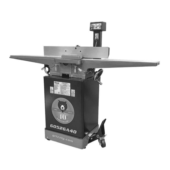
MODEL G0526A40
40TH ANNIVERSARY EDITION
6" JOINTER
OWNER'S MANUAL
(For models manufactured since 12/22)
COPYRIGHT © DECEMBER, 2022 BY GRIZZLY INDUSTRIAL, INC.
WARNING: NO PORTION OF THIS MANUAL MAY BE REPRODUCED IN ANY SHAPE
OR FORM WITHOUT THE WRITTEN APPROVAL OF GRIZZLY INDUSTRIAL, INC.
#KS22533 PRINTED IN TAIWAN
V1.12.22
***Keep for Future Reference***
Advertisement
Table of Contents

Related Manuals for Grizzly G0526A40


Summary of Contents for Grizzly G0526A40
- Page 1 (For models manufactured since 12/22) COPYRIGHT © DECEMBER, 2022 BY GRIZZLY INDUSTRIAL, INC. WARNING: NO PORTION OF THIS MANUAL MAY BE REPRODUCED IN ANY SHAPE OR FORM WITHOUT THE WRITTEN APPROVAL OF GRIZZLY INDUSTRIAL, INC. #KS22533 PRINTED IN TAIWAN V1.12.22...
- Page 2 This manual provides critical safety instructions on the proper setup, operation, maintenance, and service of this machine/tool. Save this document, refer to it often, and use it to instruct other operators. Failure to read, understand and follow the instructions in this manual may result in fire or serious personal injury—including amputation, electrocution, or death.
-
Page 3: Table Of Contents
Table of Contents INTRODUCTION ..........2 SECTION 5: ACCESSORIES ......32 Contact Info............ 2 SECTION 6: MAINTENANCE ......33 Manual Accuracy ........... 2 Schedule ............33 Identification ........... 3 Cleaning & Protecting ........33 Controls & Components ......... 4 Lubrication ........... 34 Machine Data Sheet ........ -
Page 4: Introduction
Always consider safety first, as it applies to your individual working conditions. Use this and other machinery with caution and respect. Failure to do so could result in serious personal injury, damage to equip- ment, or poor work results. Model G0526A40 (Mfd. Since 12/22) -
Page 5: Identification
Always use hold-down or push blocks when jointing material narrower than 3" or surface planing material thinner than 3". e) Never perform jointing, planing, or rabbeting cuts on pieces shorter than 8" in length. Model G0526A40 (Mfd. Since 12/22) -
Page 6: Controls & Components
ON button by turning OFF button clockwise adjusted relative to cutterhead inserts before until it pops out. ANY operations (see Page 39 for additional details). B. POWER Light: Illuminates when jointer is connected to power supply. C. ON Button: Starts motor. Model G0526A40 (Mfd. Since 12/22) - Page 7 Q. Fence Lock: Loosens to allow adjustment of fence position along width of tables. Tightens to secure fence. R. Swing Stop: When engaged, stops fence at 90°. When disengaged, allows fence to adjust for bevel cuts. Model G0526A40 (Mfd. Since 12/22)
-
Page 8: Machine Data Sheet
MACHINE DATA SHEET Customer Service #: (570) 546-9663 · To Order Call: (800) 523-4777 · Fax #: (800) 438-5901 MODEL G0526A40 6" JOINTER ‐ 40TH ANNIVERSARY EDITION Product Dimensions: Weight................................292 lbs. Width (side-to-side) x Depth (front-to-back) x Height............... 60 x 20-1/2 x 40-1/2 in. - Page 9 The information contained herein is deemed accurate as of 11/30/2022 and represents our most recent product specifications. Model G0526A40 PAGE 2 OF 3 Due to our ongoing improvement efforts, this information may not accurately describe items previously purchased. Model G0526A40 (Mfd. Since 12/22)
-
Page 10: Section 1: Safety
Never operate under the influence of drugs or injury or blindness from flying particles. Everyday alcohol, when tired, or when distracted. eyeglasses are NOT approved safety glasses. Model G0526A40 (Mfd. Since 12/22) - Page 11 Make sure they are properly installed, you experience difficulties performing the intend- undamaged, and working correctly BEFORE ed operation, stop using the machine! Contact our operating machine. Technical Support at (570) 546-9663. Model G0526A40 (Mfd. Since 12/22)
-
Page 12: Additional Safety For Jointers
Straight knives should never project MAXIMUM CUTTING DEPTH. To reduce risk of more than ⁄ " (0.125") from cutterhead body. kickback, never cut deeper than ⁄ " per pass. -10- Model G0526A40 (Mfd. Since 12/22) -
Page 13: Section 2: Power Supply
-11- Model G0526A40 (Mfd. Since 12/22) - Page 14 Two-prong outlets do not meet the grounding requirements for this machine. Do not modify or use an adapter on the plug provided—if it will not fit the outlet, have a qualified electrician install the proper outlet with a verified ground. -12- Model G0526A40 (Mfd. Since 12/22)
-
Page 15: Section 3: Setup
IMPORTANT: Save all packaging materials until you are completely satisfied with the machine and have resolved any issues between Grizzly or the shipping agent. You MUST have the original pack- aging to file a freight claim. It is also extremely helpful if you need to return your machine later. -
Page 16: Inventory
" (Foot Pedal) ....4 • Hex Nuts ⁄ "-16 (Foot Pedal) ..... 2 • Hex Bolts ⁄ "-16 x 2 ⁄ " (Foot Pedal) ..2 Box #2 Inventory (Not Shown) • Stand Assembly w/Motor ......1 -14- Model G0526A40 (Mfd. Since 12/22) -
Page 17: Cleanup
Figure 7. T23692 Orange Power Degreaser. Repeat Steps 2–3 as necessary until clean, then coat all unpainted surfaces with a quality metal protectant to prevent rust. -15- Model G0526A40 (Mfd. Since 12/22) -
Page 18: Site Considerations
Only install in an Shadows, glare, or strobe effects that may distract access restricted location. or impede the operator must be eliminated. Wall Min. 30" for Maintenance 60" 20½" = Electrical Connection Figure 8. Minimum working clearances. -16- Model G0526A40 (Mfd. Since 12/22) -
Page 19: Assembly
Evenly eling feet as needed with hex nuts so stand rests level and stable on floor. Motor Remove rear panel to access mounting holes in stand during next step. Figure 12. Pulleys correctly aligned. -17- Model G0526A40 (Mfd. Since 12/22) - Page 20 Approximately Figure 14. Location of motor mount hex nuts. " Deflection Motor Pulley Figure 16. Correct belt deflection when properly tensioned. 11. Tighten motor mount hex nuts (see Figure 14) and replace rear panel. -18- Model G0526A40 (Mfd. Since 12/22)
- Page 21 Carriage Carriage Support Base Alignment Area Bottom View Carriage Cutterhead Guard Flat Washer & Locking Jam Nut Figure 20. Fence assembly installed onto carriage base and secured. Figure 18. Cutterhead guard aligned with carriage. -19- Model G0526A40 (Mfd. Since 12/22)
- Page 22 #10 flat washers (see 16. Install fence tilt lever (see Figure 22). Figure 23). Tilt Lever Fixed Outfeed/Infeed Handle Table Handwheel Figure 22. Fence tilt lever installed. Figure 23. Table handwheel installed. -20- Model G0526A40 (Mfd. Since 12/22)
-
Page 23: Dust Collection
" flat washers (see ). Figure 26. Dust hose attached to dust port. Tug hose to make sure it does not come off. Note: A tight fit is necessary for proper performance. Figure 25. Column installed. -21- Model G0526A40 (Mfd. Since 12/22) -
Page 24: Test Run
SECTION 7: SERVICE. Factory adjustments that should be verified: • Cutterhead Inserts (Page 38). • Depth Scale Calibration (Page 40). • Fence Stop Accuracy (Page 42). • Table Parallelism (Page 45). -22- Model G0526A40 (Mfd. Since 12/22) -
Page 25: Section 4: Operations
Read books/magazines or get formal training before beginning any proj- ects. Regardless of the content in this sec- tion, Grizzly Industrial will not be held liable for accidents caused by lack of training. -23- Model G0526A40 (Mfd. Since 12/22) -
Page 26: Stock Inspection & Requirements
" Min. paint, or products that contain asbestos. Cutting these may lead to injury or machine damage. Figure 29. Minimum stock dimensions for jointer. -24- Model G0526A40 (Mfd. Since 12/22) -
Page 27: Setting Depth Of Cut
(see Figure 30). Figure 31. Location of depth-of-cut scale. Depth Indicator Scale Infeed Infeed Table Table Handwheel Lock Figure 32. Depth-of-cut components location. Figure 30. Infeed table controls. -25- Model G0526A40 (Mfd. Since 12/22) -
Page 28: Squaring Stock
Surface Plane on a Thickness Planer— Opposite face of workpiece is surface planed flat with a thickness planer. Previously Jointed Edge Previously Surface Planed Face -26- Model G0526A40 (Mfd. Since 12/22) -
Page 29: Surface Planing
Repeat Step 6 until entire surface is flat. Tip: When squaring up stock, cut opposite side of workpiece with a planer instead of the jointer to ensure boths sides are parallel. Removed Surface Figure 33. Example of surface planing operation. -27- Model G0526A40 (Mfd. Since 12/22) -
Page 30: Edge Jointing
Repeat Step 6 until the entire edge is flat. Tip: When squaring up stock, cut opposite edge of workpiece with a table saw instead of the jointer—otherwise, both edges of work- piece will not be parallel with each other. -28- Model G0526A40 (Mfd. Since 12/22) -
Page 31: Bevel Cutting
DO NOT let them get closer Figure 35. Example of fence setup for bevel cut than 4" from moving cutterhead at any time of 45°. during operation! Repeat cutting process, as necessary, until you are satisfied with the results. -29- Model G0526A40 (Mfd. Since 12/22) -
Page 32: Rabbet Cutting
However, it is possible to make rabbet cuts with workpieces up to 1" thick without removing the cutterhead guard. This is done by performing the rabbet cut with the workpiece on end (similar to when you are edge jointing). -30- Model G0526A40 (Mfd. Since 12/22) - Page 33 Re-install cutterhead guard if removed in Start jointer. Step 3. Place workpiece firmly against fence and infeed table. CAUTION: To ensure workpiece remains stable during cut, concave sides of workpiece must face toward table and fence. -31- Model G0526A40 (Mfd. Since 12/22)
-
Page 34: Section 5: Accessories
T32402—EDGE Khor G2 Safety Glasses, Tint serious personal injury or machine damage. T32404—EDGE Mazeno Safety Glasses, Clear To reduce this risk, only install accessories recommended for this machine by Grizzly. NOTICE Refer to our website or latest catalog for T32323 T32401 additional recommended accessories. -
Page 35: Section 6: Maintenance
Any other unsafe condition. Monthly Check V-belt tension, damage, or wear (Page 43). • • Clean/vacuum dust buildup from inside cabi- net and off motor. Figure 40. Recommended products for protecting unpainted cast-iron and steel. -33- Model G0526A40 (Mfd. Since 12/22) -
Page 36: Lubrication
Frequency .......... As Needed Lubricate the outfeed table leadscrew with light machine oil as needed (see Figure 42). Wipe off excess oil and sawdust with a cloth. Figure 44. Fence lubrication locations. Figure 42. Leadscrew lubrication location. -34- Model G0526A40 (Mfd. Since 12/22) -
Page 37: Section 7: Service
10. Test all legs for power; repair/replace if at fault. 11. Centrifugal switch/contact points at fault. 11. Adjust centrifugal switch/clean contact points. Replace either if at fault. 12. Motor or motor bearings at fault. 12. Replace motor. -35- Model G0526A40 (Mfd. Since 12/22) - Page 38 6. Excessive depth of cut. 6. Reduce depth of cut (Page 25). 7. Lack of proper dust collection or clogged 7. Clear blockages, ensure dust collection is operating dust port. efficiently; upgrade dust collector. -36- Model G0526A40 (Mfd. Since 12/22)
- Page 39 2. Warped infeed or outfeed table. 2. Regrind/replace table. cut produced. 3. Insert(s) not adjusted at even heights in 3. Remove, clean, and re-install any inserts that are "raised" in cutterhead (Page 38). cutterhead. -37- Model G0526A40 (Mfd. Since 12/22)
-
Page 40: Rotating/Replacing Indexable Inserts
Wear heavy leather gloves to avoid the risk of serious personal injury during the follow- ing steps. The Model G0526A40 V-helical cutterhead is equipped with 4-sided indexable carbide inserts. Each insert can be removed, rotated, and re- To replace or rotate an indexable insert: installed to use any of its four cutting edges. -
Page 41: Setting Outfeed Table Height
Infeed Outfeed Table Table Lock Lock Figure 47. Location of table locks. Place straightedge on outfeed table so it extends over cutterhead. -39- Model G0526A40 (Mfd. Since 12/22) -
Page 42: Calibrating Depth Scale
Figure 50. Infeed table adjusted even with as shown in Figure 49. outfeed table. Tighten outfeed table lock so outfeed table will not move during operation. Re-install cutterhead guard, fence, and cabinet rear access panel. -40- Model G0526A40 (Mfd. Since 12/22) -
Page 43: Adjusting Gibs
Note: Tighter gibs reduce play but make it harder to adjust tables. Repeat Steps 2–4 with outfeed table. Set outfeed table height as described in Setting Outfeed Table Height on Page 39. -41- Model G0526A40 (Mfd. Since 12/22) -
Page 44: Setting Fence Stops
Tighten jam nut loosened in Step 3. Figure 54. 90˚ swing stop engaged. Adjust the 90˚ fence stop bolt until it makes contact with 90˚ swing stop. Tighten jam nut loosened in Step 4. -42- Model G0526A40 (Mfd. Since 12/22) -
Page 45: Tensioning/Replacing V-Belt
Figure 57. Location of motor mount hex nuts. Tighten motor mount hex nuts (see Figure 57), and replace cabinet rear access panel and Press down on motor to keep tension on belt. belt guard. -43- Model G0526A40 (Mfd. Since 12/22) -
Page 46: Aligning Pulleys
(see Figure 60). edge available that will fit; however, the most accurate results will come from using a straightedge. Pulley Figure 60. Motor pulley set screw locations. Replace cabinet rear access panel and belt guard. -44- Model G0526A40 (Mfd. Since 12/22) -
Page 47: Checking/Adjusting Table Parallelism
Figure 63. Typical locations to place shims when adjusting table parallelism. Outfeed Infeed Re-check outfeed table height (refer to Setting Outfeed Table Height on Page 39), and re-adjust if necessary. Figure 61. Checking table parallelism. -45- Model G0526A40 (Mfd. Since 12/22) -
Page 48: Checking/Adjusting Cutterhead Guard
Item(s) Needed Figure 64. Cutterhead guard components. Additional Person ..........1 Precision Ruler 6" ..........1 Phillips Head Screwdriver #2 ......1 Hex Wrench 3mm ..........1 -46- Model G0526A40 (Mfd. Since 12/22) - Page 49 " flat washer and and Phillips head screw loosened in Step 4. locking jam nut. Remove scrap wood installed in Step 6 and repeat Step 2. If necessary, repeat Steps 3–8 until cutterhead guard is properly adjusted. -47- Model G0526A40 (Mfd. Since 12/22)
-
Page 50: Section 8: Wiring
Technical Support at (570) 546-9663. The photos and diagrams included in this section are best viewed in color. You can view these pages in color at www.grizzly.com. -48- Model G0526A40 (Mfd. Since 12/22) -
Page 51: Wiring Diagram
NHD NLD-22 TAICHUAN MAGNETIC SWITCH ASSY 13NO Contactor NHD C-12D 110V 14NO NHD NTH-21 110V Neutral MOTOR Motor Junction Box Start Capacitor 300MFD 125VAC 110 VAC Ground 5-15 Plug READ ELECTRICAL SAFETY -49- Model G0526A40 (Mfd. Since 12/22) ON PAGE 48! -
Page 52: Section 9: Parts
SECTION 9: PARTS We do our best to stock replacement parts when possible, but we cannot guarantee that all parts shown are available for purchase. Call (800) 523-4777 or visit www.grizzly.com/parts to check for availability. Table 35 27 BUY PARTS ONLINE AT GRIZZLY.COM! -50- Model G0526A40 (Mfd. - Page 53 P0526A40051 HEX BOLT 1/4-20 X 1/2 P0526A40022 FLAT WASHER 16MM P0526A40052 FLAT WASHER 1/4 P0526A40023 EXT RETAINING RING 10MM P0526A40058 REVOLVING HANDLE 5/16-18, 3/4 X 3-1/4 BUY PARTS ONLINE AT GRIZZLY.COM! -51- Model G0526A40 (Mfd. Since 12/22) Scan QR code to visit our Parts Store.
-
Page 54: Fence
116 P0526A40116 ROLL PIN 4 X 12 133 P0526A40133 FLAT WASHER 1/2 117 P0526A40117 SHOULDER BOLT 5/16-18 X 7/16, 1/4 X 1/2 BUY PARTS ONLINE AT GRIZZLY.COM! -52- Model G0526A40 (Mfd. Since 12/22) Scan QR code to visit our Parts Store. -
Page 55: Cutterhead
HEX NUT 3/8-24 P0526A40214 CUTTERHEAD PULLEY P0526A40207 LOCK WASHER 3/8 P0526A40215 SET SCREW 1/4-20 X 3/8 P0526A40208 STUD-SE 3/8-24 X 3-5/16, 1, 3/8" BUY PARTS ONLINE AT GRIZZLY.COM! -53- Model G0526A40 (Mfd. Since 12/22) Scan QR code to visit our Parts Store. -
Page 56: Stand
Stand 311A 311B 311C 320-1 320-4 320-2 320-3 320-5 320-7 320-6 316-1 316-2 320-8 320-9 BUY PARTS ONLINE AT GRIZZLY.COM! -54- Model G0526A40 (Mfd. Since 12/22) Scan QR code to visit our Parts Store. - Page 57 PHLP HD SCR M4-.7 X 15 383 P0526A40383 HEX BOLT 5/16-16 X 3/8 P0526A40328 MOTOR CORD 12G 3W 19" 408 P0526A40408 GREEN TAPE 100 X 1620MM BUY PARTS ONLINE AT GRIZZLY.COM! -55- Model G0526A40 (Mfd. Since 12/22) Scan QR code to visit our Parts Store.
-
Page 58: Labels & Cosmetics
Safety labels help reduce the risk of serious injury caused by machine hazards. If any label comes off or becomes unreadable, the owner of this machine MUST replace it in the original location before resuming operations. For replacements, contact (800) 523-4777 or www.grizzly.com. BUY PARTS ONLINE AT GRIZZLY.COM! -56- Model G0526A40 (Mfd. -
Page 59: Warranty & Returns
WARRANTY & RETURNS Grizzly Industrial, Inc. warrants every product it sells for a period of 1 year to the original purchaser from the date of purchase. This warranty does not apply to defects due directly or indirectly to misuse, abuse, negligence, accidents, repairs or alterations or lack of maintenance.