Table of Contents
Advertisement
Quick Links
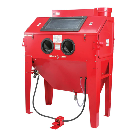
MODEL G0708
24" x 48" BLAST CABINET
OWNER'S MANUAL
(For models manufactured since 01/15)
COPYRIGHT © NOVEMBER, 2009 BY GRIZZLY INDUSTRIAL, INC., REVISED JANUARY, 2018 (HE)
WARNING: NO PORTION OF THIS MANUAL MAY BE REPRODUCED IN ANY SHAPE
OR FORM WITHOUT THE WRITTEN APPROVAL OF GRIZZLY INDUSTRIAL, INC.
#CR12333 PRINTED IN CHINA.
Advertisement
Table of Contents

Related Manuals for Grizzly G0708


Summary of Contents for Grizzly G0708
- Page 1 OWNER'S MANUAL (For models manufactured since 01/15) COPYRIGHT © NOVEMBER, 2009 BY GRIZZLY INDUSTRIAL, INC., REVISED JANUARY, 2018 (HE) WARNING: NO PORTION OF THIS MANUAL MAY BE REPRODUCED IN ANY SHAPE OR FORM WITHOUT THE WRITTEN APPROVAL OF GRIZZLY INDUSTRIAL, INC.
- Page 2 This manual provides critical safety instructions on the proper setup, operation, maintenance, and service of this machine/tool. Save this document, refer to it often, and use it to instruct other operators. Failure to read, understand and follow the instructions in this manual may result in fire or serious personal injury—including amputation, electrocution, or death.
-
Page 3: Table Of Contents
Table of Contents INTRODUCTION ..........................2 Manual Accuracy ........................2 Contact Info ..........................2 Machine Description ........................2 Identification ..........................3 Machine Data Sheet ........................4 SECTION 1: SAFETY ........................6 Safety Instructions for Machinery ....................6 Additional Safety for Blast Cabinets ................... 8 SECTION 2: CIRCUIT REQUIREMENTS .................. -
Page 4: Introduction
Any updates to your model of machine will be reflected in these documents An internal set of fluorescent work lamps provide as soon as they are complete. -
Page 5: Identification
Gloves A. Power Switch G. Foot Pedal Blasting Switch B. Dust Collector H. Pressure Regulator w/Gauge C. Fluorescent Lamp Assembly Front Loading Door Latch D. Side-Loading Door E. Metering Valve and Dump Chute Viewing Window Model G0708 (Mfd. Since 1/15) -
Page 6: Machine Data Sheet
Maximum Abrasive Capacity ............................250 lbs. Suggested Abrasive Capacity ............................55 lbs. Abrasive Type ................................Dry Only Load & Unload Access ............................. Front and Sides Maximum Load Capacity ..............................88 lbs. Design Type ................................Floor Model Model G0708 Page 1 of 2 Model G0708 (Mfd. Since 1/15) - Page 7 Included Dust Collector Filter Screened Work Table Adjustable Hopper Flow Valve Foot Pedal Blasting Control Hopper Dump Gate Easy-Clean Dust Collector Reusable Dust Collector Filter Element External Lighting System Model G0708 Page 2 of 2 Model G0708 (Mfd. Since 1/15)
-
Page 8: Section 1: Safety
Be aware of running machinery. Never operate under the dust hazards associated with each workpiece influence of drugs or alcohol, when tired, or when material, and always wear a NIOSH-approved distracted. respirator to reduce your risk. Model G0708 (Mfd. Since 1/15) - Page 9 Contact our Technical Support Department at around flammables, or in poorly-lit areas. Keep (570) 546-9663. work area clean, dry, and well lighted to mini- mize risk of injury. Model G0708 (Mfd. Since 1/15)
-
Page 10: Additional Safety For Blast Cabinets
If normal safety pre- Failure to do so could result in serious per- sonal injury, damage to equipment, or poor cautions are overlooked or ignored, serious personal injury may occur. work results. Model G0708 (Mfd. Since 1/15) -
Page 11: Section 2: Circuit Requirements
Minimum Circuit Size ......15 Amps exceed 50 feet in length! • The extension cord must have a ground wire and plug pin. • A qualified electrician MUST size cords over 50 feet long to prevent motor damage. Model G0708 (Mfd. Since 1/15) -
Page 12: Section 3: Setup
Save the containers and all packing materials for possible inspection by the carrier or its agent. Otherwise, filing a freight claim can be difficult. When you are completely satisfied with the condi- tion of your shipment, inventory the contents. -10- Model G0708 (Mfd. Since 1/15) -
Page 13: Inventory
—Cabinet Screws ⁄ -20 x ⁄ " ....26 obtained at your local hardware store. — Flange Nuts ⁄ "-20 ........ 26 Spare Front Door Seal ⁄ " x ⁄ " x 79" ..1 -11- Model G0708 (Mfd. Since 1/15) -
Page 14: Hardware Recognition Chart
Hardware Recognition Chart -12- Model G0708 (Mfd. Since 1/15) -
Page 15: Site Considerations
Only install in an Shadows, glare, or strobe effects that may distract access restricted location. or impede the operator must be eliminated. 92" 22" 22" 35" Figure 3. Space required for full range of movement. -13- Model G0708 (Mfd. Since 1/15) -
Page 16: Mounting To Shop Floor
Anchor studs are stronger and more per- manent alternatives to lag shield anchors; however, they will stick out of the floor, which may cause a tripping hazard if you decide to move your machine. -14- Model G0708 (Mfd. Since 1/15) -
Page 17: Air Supply Setup
If even small amounts of fine media dust enter the when not in use. compressor through the intake or during general service, rings, pistons, valves, and bearings can be quickly destroyed. -15- Model G0708 (Mfd. Since 1/15) -
Page 18: Assembly
⁄ -20 x ⁄ " cabinet screws. Fasten the pressure gauge and regulator "L" bracket (Figure 7) to the left front leg using two cabinet screws and flange nuts. Figure 9. Suction port baffle. -16- Model G0708 (Mfd. Since 1/15) - Page 19 12. Working from inside of the canister, insert the canister plunger through the canister wall so it can be seen protruding from the outside of the canister. -17- Model G0708 (Mfd. Since 1/15)
- Page 20 The pedal may also be fastened to the floor if and adjust the receivers so the doors slightly the unit will not be moved. compress the foam seal when closed (Figure 14). Receiver Figure 14. Door latched closed. Figure 16. Foot pedal positioning. -18- Model G0708 (Mfd. Since 1/15)
-
Page 21: Test Run
Make sure all tools and objects used during setup are cleared away from the machine. Make sure that the power switch is in the OFF position (see Figure 17). Figure 17. ON/OFF switch. -19- Model G0708 (Mfd. Since 1/15) - Page 22 Put on safety glasses, and connect the blast power supply. cabinet to the air supply. Adjust the regulator knob to 120 PSI as shown on the gauge. -20- Model G0708 (Mfd. Since 1/15)
-
Page 23: Section 4: Operations
Remove water, oil, grease, and loose paint projects. Regardless of the content in this or scale from the workpiece, then place the section, Grizzly Industrial will not be held workpiece into blast cabinet. liable for accidents caused by lack of train- ing. -
Page 24: Basic Operation
6mm tip is used most often. Refer to Page 25 for air pressure and media options. This section details the correct order of operations for using the Model G0708. To use the blast cabinet: Conduct the daily check listed in Maintenance on Page 29. - Page 25 (Figure 22). Figure 24. Main power button. 12. Point the blast gun tip at the workpiece in a direction where the ricochetting spray of abrasive will not contact the windows. Figure 22. Properly latched door. -23- Model G0708 (Mfd. Since 1/15)
- Page 26 120 PSI on this machine; however, most media blasting operations should occur at 80 PSI. Figure 26. Canister plunger. 15. When media blasting is complete, disconnect the cabinet from power and the air supply. -24- Model G0708 (Mfd. Since 1/15)
-
Page 27: Blasting Media
However, the cutting ability at lower air pressure and CFM can be poor—with a higher hazard of silicosis and machine clogging. Many sand-type media contain free silica and present a health hazard for silicosis. -25- Model G0708 (Mfd. Since 1/15) - Page 28 Various grit sizes can be used from basic cleaning of most materials. light blasting operations to heavy-duty rust, paint, and mill scale removal. The resulting finish is a good surface ready to anchor and bond coatings and paints. -26- Model G0708 (Mfd. Since 1/15)
- Page 29 For the Model G0708, filter cleaning inter- val will have to be increased to maintain flow. —Ground Walnut: (4.5-5) This is a soft media that is produced from crushed or ground walnut shells.
-
Page 30: Media Notes
Media Notes -28- Model G0708 (Mfd. Since 1/15) -
Page 31: Section 5: Accessories
H7359—Campbell Hausfeld: 5 HP, 60-gallon H2499—Small Half-Mask Respirator Air Compressor H3631—Medium Half-Mask Respirator If you do not need to operate the Model G0708 H3632—Large Half-Mask Respirator at full capacity of 16 CFM @ 120 PSI, the H7359 H3635—Cartridge Filter Pair P100... -
Page 32: Section 6: Maintenance
Empty cabinet, wipe down inside and inspect for leaks or damage. • Cover windows and repaint bare metal por- tions of cabinet. Figure 30. Dust collector service. • Remove filter and clean/replace as required. -30- Model G0708 (Mfd. Since 1/15) -
Page 33: Section 7: Service
(Page 22). 8. Blast gun is damaged or has bad seals. 8. Disassemble blast gun, clean and reseal. 9. Foot valve is damaged, clogged, or has 9. Clean and reseal foot valve. leaks. -31- Model G0708 (Mfd. Since 1/15) -
Page 34: Filter Replacement
Spin the wing nut off of the retaining stud, and remove the filter (Figure 31). Place a new five-micron filter over the retain- ing stud, then reinstall the wing nut and the dust collector. -32- Model G0708 (Mfd. Since 1/15) -
Page 35: Motor Brush Replacement
(Figure 32). Retainer Motor Cover Latch Brush Canister Housing Figure 34. Retainer removal. Figure 32. Motor cover. Using the Phillips screwdriver, remove the four motor cover screws and the cover (Figure 32). -33- Model G0708 (Mfd. Since 1/15) - Page 36 Reassemble the housings with the brass sleeves and the new carbon brushes (Figure 36) and set aside. Figure 38. Brush power lead location. Inspect the commutator surface (Figure 37). Carbon Tracking on Commutator Surface Figure 37. Commutator. -34- Model G0708 (Mfd. Since 1/15)
- Page 37 15. Route the motor cover and the dust collector assembly into the canister, and latch the dust collector in place. 16. Test the dust collector operation. Correct Incorrect Figure 40. Safe power wire routing. -35- Model G0708 (Mfd. Since 1/15)
-
Page 38: Section 8: Wiring
Technical source. Support at (570) 546-9663. The photos and diagrams included in this section are best viewed in color. You can view these pages in color at www.grizzly.com. -36- Model G0708 (Mfd. Since 1/15) -
Page 39: Wiring Diagram
Ground Worklamp Assembly Bulb FL T8 18W Ballast 110V-130V Bulb FL T8 18W Ground Machine ON/OFF Switch 110 VAC Inline Plug & Recepticle Dust Collector Motor Ground READ ELECTRICAL SAFETY -37- Model G0708 (Mfd. Since 1/15) ON PAGE 35! -
Page 40: Air System Diagram
Two-Stage Dedicated Media Blasting Air Compresssor Air Dryer System Blast Cabinet Blast Gun Blast Cabinet Air Regulator Cabinet Hopper with Media Media Metering Valve Blast Cabinet Foot Valve READ ELECTRICAL SAFETY -38- Model G0708 (Mfd. Since 1/15) ON PAGE 35! -
Page 41: Electrical Component Locations
Figure 42. Lamp and power switch system. Figure 43. Lamp ballast. Figure 45. Power switch and lamp connection. Figure 46. Dust collector motor. Figure 44. Dust collector unit. READ ELECTRICAL SAFETY -39- Model G0708 (Mfd. Since 1/15) ON PAGE 35! -
Page 42: Section 9: Parts
SECTION 9: PARTS 39-1 39-2 39-3 39-4 39-5 39-6 39-7 39-8 39-9 39-10 49-1 -40- Model G0708 (Mfd. Since 1/15) -
Page 43: Parts List
BALLAST 110V-130V 40-WATT 39-5 P0708039-5 MAIN HOUSING P0708080 MACHINE POWER CORD 3-WIRE 14-GA 39-6 P0708039-6 MALE POWER CORD 3-WIRE 14-GA P0708081 FEMALE POWER CORD 3-WIRE 14-GA 39-7 P0708039-7 CARTRIDGE FILTER 5-MICRON P0708099 FENDER WASHER 6MM -41- Model G0708 (Mfd. Since 1/15) -
Page 44: Machine Label Placement & Parts List
MUST maintain the original location and readability of the labels on the machine. If any label is removed or becomes unreadable, REPLACE that label before using the machine again. Contact Grizzly at (800) 523-4777 or www.grizzly.com to order new labels. -42-... - Page 45 Would you recommend Grizzly Industrial to a friend? _____ Yes _____No Would you allow us to use your name as a reference for Grizzly customers in your area? Note: We never use names more than 3 times. _____ Yes _____No 10.
- Page 46 FOLD ALONG DOTTED LINE Place Stamp Here GRIZZLY INDUSTRIAL, INC. P.O. BOX 2069 BELLINGHAM, WA 98227-2069 FOLD ALONG DOTTED LINE Send a Grizzly Catalog to a friend: Name_______________________________ Street_______________________________ City______________State______Zip______ TAPE ALONG EDGES--PLEASE DO NOT STAPLE...
-
Page 47: Warranty And Returns
WARRANTY AND RETURNS Grizzly Industrial, Inc. warrants every product it sells for a period of 1 year to the original purchaser from the date of purchase. This warranty does not apply to defects due directly or indirectly to misuse, abuse, negligence, accidents, repairs or alterations or lack of maintenance.