Table of Contents
Advertisement
Quick Links
For questions or help with this product contact Tech Support at (570) 546-9663 or techsupport@grizzly.com
The following changes were recently made since the owner's manual was printed:
•
The motor changed.
•
The start capacitor changed.
Aside from this information, all other content in the owner's manual applies and MUST be read and under-
stood for your own safety. IMPORTANT: Keep this update with the owner's manual for future reference.
For questions or help, contact our Tech Support at (570) 546-9663 or techsupport@grizzly.com.
Revised Parts
39V3
REF
PART #
DESCRIPTION
39V3
P0792039V3
MOTOR 2HP 220V 1-PH V3.04.18
39V3-8V2 P0792039V3-8V2 S CAPACITOR 100M 275V 1-5/8 X 3-3/8 V3.04.22
WARNING: NO PORTION OF THIS MANUAL MAY BE REPRODUCED IN ANY SHAPE
OR FORM WITHOUT THE WRITTEN APPROVAL OF GRIZZLY INDUSTRIAL, INC.
READ THIS FIRST
39V3-8V2
COPYRIGHT © MAY, 2022 BY GRIZZLY INDUSTRIAL, INC.
#SS22340 PRINTED IN CHINA
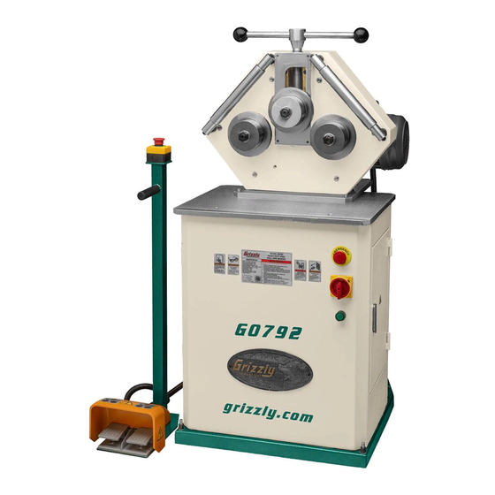
Model G0792
***IMPORTANT UPDATE***
For Machines Mfd. Since 04/18
and Owner's Manual Revised 03/16
Revised Specifications
Electrical:
Full-Load Current Rating . .......................10A
Motor:
Amps ......................................................10A
Advertisement
Table of Contents

Related Manuals for Grizzly G0792


Summary of Contents for Grizzly G0792
- Page 1 ***IMPORTANT UPDATE*** For Machines Mfd. Since 04/18 and Owner's Manual Revised 03/16 For questions or help with this product contact Tech Support at (570) 546-9663 or techsupport@grizzly.com The following changes were recently made since the owner's manual was printed: •...
- Page 2 (Replaces Page 28 in Owner's Manual) Electrical Components Emergency Stop Button Emergency Stop Button Master Power Switch Relay Transformer Contactor Power Button Foot Pedal Controls Figure 32. Foot pedal assembly, emergency stop button, and forward-facing controls. Terminal Figure 30. Electrical cabinet components. Figure 33. Motor junction box and starting switch. Figure 31. Foot pedal wiring. G0792 Update (Mfd. Since 04/18)
- Page 3 SIEMENS 3TB41 24V SIEMENS 3TB41 24V SIEMENS 3TB41 24V 14NO 22NC 32NC 44NO 14NO 22NC 32NC 44NO 14NO 22NC 32NC 44NO POWER Button To Foot Pedal & E-Stop To Motor Page 30 Page 30 6-15 Plug Ground G0792 Update (Mfd. Since 04/18)
- Page 4 Page 29 To Control Panel Page 29 Foot Pedal & E-Stop Diagram Ground Ground Foot Pedal Controls Foot Pedal Controls To Control Panel ZB2-BE102 Page 29 To Control Panel ZB2-BE102 E-Stop Button Page 29 E-Stop Button G0792 Update (Mfd. Since 04/18)
- Page 5 OWNER'S MANUAL (For models manufactured since 12/15) COPYRIGHT © NOVEMBER, 2015 BY GRIZZLY INDUSTRIAL, INC., REVISED MARCH, 2016 (MN) WARNING: NO PORTION OF THIS MANUAL MAY BE REPRODUCED IN ANY SHAPE OR FORM WITHOUT THE WRITTEN APPROVAL OF GRIZZLY INDUSTRIAL, INC.
- Page 6 This manual provides critical safety instructions on the proper setup, operation, maintenance, and service of this machine/tool. Save this document, refer to it often, and use it to instruct other operators. Failure to read, understand and follow the instructions in this manual may result in fire or serious personal injury—including amputation, electrocution, or death.
-
Page 7: Table Of Contents
Table of Contents INTRODUCTION ..........................2 Contact Info ..........................2 Manual Accuracy ........................2 Identification ..........................3 Controls & Components ......................4 Machine Data Sheet ........................5 SECTION 1: SAFETY ........................6 Safety Instructions for Machinery ....................6 Additional Safety for Ring Roll Benders ..................8 SECTION 2: POWER SUPPLY ...................... -
Page 8: Introduction
ID label (see below). This information is required for us to provide proper tech support, and it helps us determine if updated documenta- tion is available for your machine. Manufacture Date Serial Number Model G0792 (Mfd. Since 12/15) -
Page 9: Identification
Headstock Control Pedestal Main Power Switch Left Roller Feed Control Right Roller Power ON Electrical Panel Feed Control Button Access Door To reduce your risk of serious injury, read this entire manual BEFORE using machine. Model G0792 (Mfd. Since 12/15) -
Page 10: Controls & Components
D. Upper Roller Crank Handle: Adjusts posi- tion of upper roller relative to lower rollers. Moving upper roller closer to lower rollers increases bend in workpiece. Model G0792 (Mfd. Since 12/15) -
Page 11: Machine Data Sheet
MODEL G0792 HEAVY-DUTY RING ROLL PIPE BENDER Product Dimensions: Weight ................................... 583 lbs. Width (side-to-side) x Depth (front-to-back) x Height ..................29 x 40 x 51 in. Foot Print (Length/Width) .............................40 x 24-1/2 in. Shipping Dimensions: Type ..................................Wood Crate Weight .................................... 626 lbs. -
Page 12: Section 1: Safety
Everyday ery. Never operate under the influence of drugs or eyeglasses are NOT approved safety glasses. alcohol, when tired, or when distracted. Model G0792 (Mfd. Since 12/15) - Page 13 EXPERIENCING DIFFICULTIES. If at any time debris. Make sure they are properly installed, you experience difficulties performing the intend- undamaged, and working correctly BEFORE ed operation, stop using the machine! Contact our operating machine. Technical Support at (570) 546-9663. Model G0792 (Mfd. Since 12/15)
-
Page 14: Additional Safety For Ring Roll Benders
FOOT PROTECTION. Heavy workpieces acci- dentally falling off of rollers during operation can cause crushing injuries to the feet of operator. To reduce your risk, wear steel-toed boots when using machine. Model G0792 (Mfd. Since 12/15) -
Page 15: Section 2: Power Supply
To reduce the risk of these hazards, avoid over- loading the machine during operation and make sure it is connected to a power supply circuit that meets the specified circuit requirements. Model G0792 (Mfd. Since 12/15) - Page 16 Minimum Gauge Size ......14 AWG all local codes and ordinances. Maximum Length (Shorter is Better)..50 ft. -10- Model G0792 (Mfd. Since 12/15)
-
Page 17: Section 3: Setup
Grizzly or the shipping agent. You MUST have the original pack- Item Inventory (Figure 4) aging to file a freight claim. -
Page 18: Cleanup
Figure 5. T23692 Orange Power Degreaser. Repeat Steps 2–3 as necessary until clean, then coat all unpainted surfaces with a quality metal protectant to prevent rust. -12- Model G0792 (Mfd. Since 12/15) -
Page 19: Site Considerations
Wall Min. 30" for Maintenance Keep Keep 40" Workpiece Workpiece Loading Area Loading Area Unobstructed Unobstructed 29" = Electrical Connection Illustration Not To Scale Figure 6. Minimum working clearances. -13- Model G0792 (Mfd. Since 12/15) -
Page 20: Assembly
Assembly Lifting & Placing The Model G0792 comes with the headstock in the horizontal position. To safely lift the machine, you must first adjust the headstock to the vertical HEAVY LIFT! position and install the upper roller crank handle. Straining or crushing injury... -
Page 21: Anchoring To Floor
Concrete ommend placing it on machine mounts, as these provide an easy method for leveling and they have Drilled Hole vibration-absorbing pads. Figure 10. Popular method for anchoring machinery to a concrete floor. -15- Model G0792 (Mfd. Since 12/15) -
Page 22: Test Run
Connect machine to power source. to machine. Emergency Stop/RESET but- ton safety feature is not working correctly. This safety feature must work properly before proceeding with regular operations. Call Tech Support for help. -16- Model G0792 (Mfd. Since 12/15) -
Page 23: Section 4: Operations
Read books/magazines or get formal training before beginning any proj- ects. Regardless of the content in this sec- tion, Grizzly Industrial will not be held liable for accidents caused by lack of training. -17- Model G0792 (Mfd. Since 12/15) -
Page 24: Rolling Arcs
Move upper roller down until it just touches workpiece, as shown in Figure 14, then con- nect machine to power. The Model G0792 Ring Roll Pipe Bender can be used to create arcs, circles, and spirals by feed- ing the pipe back and forth through the machine... - Page 25 To position headstock in horizontal position: DISCONNECT MACHINE FROM POWER! Remove two cap screws shown in Figure 20. Figure 18. Example bend after multiple bending passes. Screws Figure 20. Location of cap screws that secure headstock in vertical position. -19- Model G0792 (Mfd. Since 12/15)
-
Page 26: Rolling Compound Arcs
Use cap screws removed in Step 2 to secure headstock to horizontal mount (see Figure Rolling a compound arc requires accessory roll- 21). ers that do not come with the Model G0792, such as Round Material Dies offered by Grizzly (see Page 22 for more information). Horizontal... - Page 27 Note: Due to differences in workpiece mate- rials and achievable shapes, you will likely need to experiment with a combination of adjustments to get the results you want. This includes rotating the lower adjustment bolt (see Figure 23). -21- Model G0792 (Mfd. Since 12/15)
-
Page 28: Section 5: Accessories
Figure 25. Model G7153 Universal Bender. Round Material Dies Expand your bending capability with these round T20451 material dies from Grizzly, allowing you to bend H7194 round stock for marine hand rails, coils of tubing, Figure 27. Assortment of basic eye protection. -
Page 29: Section 6: Maintenance
Cap Screw M8-1.25 x 16 Protecting Drive Gear Cover Cleaning the Model G0792 is relatively easy. Wipe down all unpainted and machined surfaces Drive Shaft daily to keep them rust free and in top condition. Cover This includes any surface that is vulnerable to rust if left unprotected. - Page 30 Leadscrew Drive Gears Oil Type ..Grizzly T23962 or ISO 68 Equivalent Grease Type ..T23964 or NLGI#2 Equivalent Oil Amount ......... As Needed Lubrication ....Every 50 Operating Hours Lubrication Frequency ....... As Needed The drive gears, shown in Figure 29, should...
-
Page 31: Section 7: Service
5. Roller(s) at fault/incorrectly installed. 5. Ensure rollers are correctly installed, replace if necessary. 6. Centrifugal switch at fault. 6. Replace. 7. Motor bearings at fault. 7. Test by rotating shaft; rotational grinding/loose shaft requires bearing replacement. -25- Model G0792 (Mfd. Since 12/15) - Page 32 Workpiece does not 1. Not enough bending pressure. 1. Increase bending pressure of upper roller. move when rollers 2. Grease/oil on workpiece/rollers, causing 2. Thoroughly clean workpiece/rollers to prevent rotate. rollers to slip against workpiece. slipping. -26- Model G0792 (Mfd. Since 12/15)
-
Page 33: Section 8: Wiring
Technical Support at (570) 546-9663. The photos and diagrams included in this section are best viewed in color. You can view these pages in color at www.grizzly.com. -27- Model G0792 (Mfd. Since 12/15) -
Page 34: Electrical Components
Figure 32. Foot pedal assembly, emergency stop button, and forward-facing controls. Terminal Figure 30. Electrical cabinet components. Figure 33. Motor junction box and starting switch. Figure 31. Foot pedal wiring. READ ELECTRICAL SAFETY -28- Model G0792 (Mfd. Since 12/15) ON PAGE 27! -
Page 35: Electrical Panel Wiring Diagram
Contactor LA158-BW SIEMENS 3TB41 24V SIEMENS 3TB41 24V SIEMENS 3TB41 24V 14NO 22NC 32NC 14NO 22NC 44NO 32NC 44NO 14NO 22NC 32NC 44NO POWER Button 6-15 Plug Ground READ ELECTRICAL SAFETY -29- Model G0792 (Mfd. Since 12/15) ON PAGE 27! -
Page 36: Motor Diagram
3 3 2 2 1 1 ESS1-40 Starting Switch To Control Panel Page 29 Foot Pedal & E-Stop Diagram Ground Foot Pedal Controls To Control Panel ZB2-BE102 Page 29 E-Stop Button READ ELECTRICAL SAFETY -30- Model G0792 (Mfd. Since 12/15) ON PAGE 27! -
Page 37: Section 9: Parts
SECTION 9: PARTS We do our best to stock replacement parts when possible, but we cannot guarantee that all parts shown are available for purchase. Call (800) 523-4777 or visit www.grizzly.com/parts to check for availability. Main 46 47 53 81... - Page 38 ELEVATION SLIDE BLOCK P0792102 PHLP HD SCR M5-.8 X 26 P0792044 GEAR SHAFT P0792103 PHLP HD SCR M5-.8 X 95 P0792045 COMPRESSION SPRING 10.5 X 15 P0792104 FLEXIBLE CONDUIT 7/8" X 24" (PLASTIC) P0792046 SPRING SHAFT -32- Model G0792 (Mfd. Since 12/15)
-
Page 39: Electrical Panel
221 P0792221 FLAT WASHER 4MM 210 P0792210 POWER BUTTON ANIUEC LA158-BE101 222 P0792222 CAP SCREW M6-1 X 12 211 P0792211 DIN RAIL (MIDDLE) 223 P0792223 STRAIN RELIEF M20-2 TYPE-3 212 P0792212 CONTACTOR SIEMENS 3TB41 22-0X -33- Model G0792 (Mfd. Since 12/15) -
Page 40: Labels & Cosmetics
FOR GRIZZLY MACHINES ONLY! DO NOT REPRODUCE OR CHANGE THIS ARTWORK G0792 Machine Labels B WITHOUT WRITTEN APPROVAL! Grizzly will not accept labels changed without approval. FOR GRIZZLY MACHINES ONLY! DO NOT REPRODUCE OR CHANGE THIS R GRIZZLY MACHINES ONLY! DO NOT REPRODUCE OR CHANGE THIS ARTWORK •... - Page 41 Would you recommend Grizzly Industrial to a friend? _____ Yes _____No Would you allow us to use your name as a reference for Grizzly customers in your area? Note: We never use names more than 3 times. _____ Yes _____No 10.
- Page 42 FOLD ALONG DOTTED LINE Place Stamp Here GRIZZLY INDUSTRIAL, INC. P.O. BOX 2069 BELLINGHAM, WA 98227-2069 FOLD ALONG DOTTED LINE Send a Grizzly Catalog to a friend: Name_______________________________ Street_______________________________ City______________State______Zip______ TAPE ALONG EDGES--PLEASE DO NOT STAPLE...
-
Page 43: Warranty & Returns
WARRANTY & RETURNS Grizzly Industrial, Inc. warrants every product it sells for a period of 1 year to the original purchaser from the date of purchase. This warranty does not apply to defects due directly or indirectly to misuse, abuse, negligence, accidents, repairs or alterations or lack of maintenance.