
Related Manuals for Grizzly G0937


Summary of Contents for Grizzly G0937
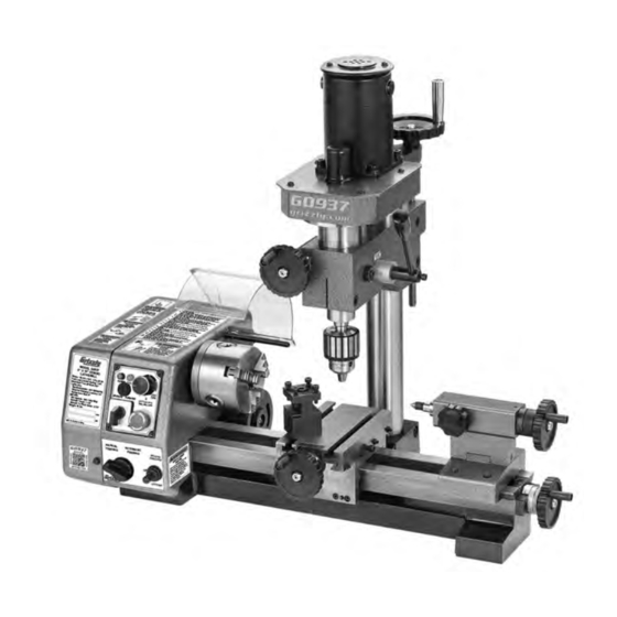
- Page 1 MODEL G0937 6" X 10" COMBO LATHE/MILL OWNER'S MANUAL (For models manufactured since 12/20)
- Page 2 This manual provides critical safety instructions on the proper setup, operation, maintenance, and service of this machine/tool. Save this document, refer to it often, and use it to instruct other operators. Failure to read, understand and follow the instructions in this manual may result in fire or serious personal injury—including amputation, electrocution, or death.
-
Page 3: Table Of Contents
CONTENTS Machine Data Sheet................Important Safety Instructions............Power Supply..................Features and Legend................. 1. The Headstock................. 2. The Running Gear..............3. The Tailstock................4. The Saddle and the Cross-Slide..........5. The Mill/Drill Head..............6. The Motor................. Inventory..................... Unpacking & Preparing for Use............Mounting the Machine............... -
Page 4: Machine Data Sheet
MACHINE DATA SHEET Customer Service #: (570) 546-9663 · To Order Call: (800) 523-4777 · Fax #: (800) 438-5901 MODEL G0937 6" X 10" COMBO LATHE/MILL Product Dimensions: Weight................................99 lbs. Width (side-to-side) x Depth (front-to-back) x Height............... 24-1/2 x 21 x 22-1/2 in. - Page 5 Main Specifications: Lathe Info Swing Over Bed............................6 in. Distance Between Centers........................10 in. Swing Over Cross Slide..........................3 in. Maximum Tool Bit Size........................... 5/16 in. Carriage Travel............................7 in. Cross Slide Travel..........................2-7/8 in. Spindle Bore............................11/32 in. Spindle Taper............................MT#2 Number Of Spindle Speeds........................
-
Page 6: Important Safety Instructions
2. Do not attempt to use inappropriate attachments in an attempt to exceed the tool's capacity. Approved accessories are available from Grizzly Industrial, Inc. 3. Check for damaged parts before using any machine. Any part that appears damaged should be carefully checked to determine that it will operate properly and perform its intended function. - Page 7 For Your Own Safety, Read Instruction Manual Before Operating This Machine The purpose of safety symbols is to attract your attention to possible hazardous conditions. This manual uses a series of symbols and signal words intended to convey the level of impor- tance of the safety messages.
- Page 8 WEARING PROPER APPAREL. Do not wear FORCING MACHINERY. Do not force machine. clothing, apparel or jewelry that can become It will do the job safer and better at the rate for entangled in moving parts. Always tie back or which it was designed. cover long hair.
- Page 9 Additional Safety for Metal Lathes The primary risks of operating a Metal Lathe are as follows: You can be seriously injured or killed by getting entangled in, crushed between, or struck by rotating parts on a lathe. You can be struck with deadly force by unsecured tools or workpieces attached to rotating objects. To reduce your risk of serious injury when operating this machine, completely heed and understand the following: CLOTHING, JEWELRY &...
- Page 10 Additional Safety for Mills/Drills You can be seriously injured or killed by getting clothing, jewelry, or long hair entangled with rotating cutter/spindle. You can be severely cut or have fingers amputated from contact with rotating cutters. You can be blinded or struck by broken cutting tools, metal chips, workpieces, or adjustment tools thrown from the rotating spindle with great force.
- Page 11 Additional Lathe Chuck Safety ENTANGLEMENT. Entanglement with a rotat- CHUCK CAPACITY. Avoid exceeding the capacity ing chuck can lead to death, amputation, broken of the chuck by clamping an oversized workpiece. bones, or other serious injury. Never attempt to If the workpiece is too large to safely clamp with slow or stop the lathe chuck by hand, and always the chuck, use a faceplate or a larger chuck if pos- roll up long sleeves, tie back long hair, and remove...
-
Page 12: Power Supply
POWER SUPPLY Availability Before installing the machine, consider the avail- ability and proximity of the required power supply Serious injury could occur if you connect circuit. If an existing circuit does not meet the machine to power before completing setup requirements for this machine, a new circuit must process. - Page 13 Grounding & Plug Requirements Improper connection of the equipment-grounding wire can result in a risk of electric shock. The This machine MUST be grounded. In the event wire with green insulation (with or without yellow of certain malfunctions or breakdowns, grounding stripes) is the equipment-grounding wire.
-
Page 14: Features And Legend
FEATURES This multi-purpose machine is designed for processing small parts, both metal and non-metal, into various shapes (e.g., square, offset, cylindrical and conical, etc.) by cutting, drilling, or milling. It can also be used for cutting metric or inch threads. With the drilling/milling head installed, the machine can successfully perform drilling or milling processes. -
Page 15: The Running Gear
THE MILL/DRILL HEAD To use the Model G0937 as a mill or drill, first confirm the mill/drill chuck is securely installed on the mill/ drill arbor/spindle (Morse #1). Once the chuck is installed, it is very difficult to separate the assembly. We recommend obtaining a new arbor if you would like to use a different chuck. -
Page 16: Inventory
INVENTORY Descriptions Model G0937 Combo Lathe/Mill Hex Wrenches 2, 3, 4, 6mm 1 Each Wrenches 5.5 X 7, 8 X 10mm 1 Each Spanner Wrenches 1 Each 28 X 32, 38 X 42mm Tailstock Center MT#1 Plastic Oil Can Fuse... -
Page 17: Unpacking & Preparing For Use
UNPACKING & PREPARING FOR USE UNPACKING & PREPARING FOR USE On receipt, carefully unpack the machine and inspect to ensure that no damage was suffered in transit and all parts are accounted for. Should any damage be apparent, or parts missing, please contact customer service immediately. -
Page 18: Starting Procedure
STARTING PROCEDURE A. DURING INSTALLATION/INITIAL START Taking all precautions previously stated, ensure the cross-slide is well away from the chuck and the clutch turned left for automatic feeding. Close the chuck’s protective cover, and connect the machine to power. Lathe Spindle Break-In Turn the power supply switch (C) to the ‘Cutting’... -
Page 19: Operation
2. Select ‘Cutting’ or ‘Drill/Mill’ by turning the power supply switch (C) as your operation requires. 3. Set the Forward/Off/Reverse switch on the main control panel to the 'Forward' position. 4. For cutting, select either manual or automatic feeding with the clutch, as operation requires. IMPORTANT: This should ALWAYS be a deliberate, conscious action. -
Page 20: Settings & Adjustments
AFTER USE Remove all swarf from the machine and thoroughly clean all surfaces. If coolant has been used, ensure it has completely drained from the tray. Components should be dry, and all machined surfaces should be lightly oiled. Always remove cutting tools and store machine in a safe place when not in use. MOTOR BRUSHES The motor brushes may be changed by unscrewing the caps at the end of the motor. - Page 21 B. CROSS-SLIDE FEED HANDLE The cross-slide feed should run smoothly, and the scale must rotate with the handle. If any stiffness occurs, it is probably the result of swarf lodging between the mating surfaces. Undo the screw securing the handwheel, remove the handwheel, and pull off the collar with the scale taking great care to retain the small spring plate which sits in a groove beneath the collar.
-
Page 22: Wiring Diagram
WIRING DIAGRAM K3 K4 XMT-1115 GAN L1 P1 P2 P3 110V PE-2 PE-1 100-120V 50-60Hz Item No. Name Item No. Name XMT-1115 PC Board Choose Switch Lathe Motor Change Switch Mill Head Motor Limit Switch Potentiometer Fuse Emergency Stop Switch Power Indicator Light... -
Page 23: Parts
PARTS Mill BUY PARTS ONLINE AT GRIZZLY.COM! Scan QR code to visit our Parts Store. - Page 24 MILL HEADSTOCK P0937225 SET SCREW M6-1 X 20 P0937156 SPINDLE COVER P0937257 MILL CARBON BRUSH (2-PC SET) P0937157 EXT RETAINING RING 20MM P0937258 MILL CARBON BRUSH COVER BUY PARTS ONLINE AT GRIZZLY.COM! Scan QR code to visit our Parts Store.
- Page 25 HEX NUT M4-.7 P0937012 SPINDLE BOX COVER REF PART # DESCRIPTION REF PART # DESCRIPTION BUY PARTS ONLINE AT GRIZZLY.COM! Scan QR code to visit our Parts Store. P0937013 SPINDLE P0937080 FLAT WASHER 5MM P0937014 KEY 3 X 3 X 6 RE...
- Page 26 GEAR SHAFT BRACKET P0937254 TAP SCREW M3 X 8 P0937078 HEX NUT M5-.8 P0937255 LATHE CARBON BRUSH (2-PC SET) P0937079 SUPPORT PLATE P0937256 LATHE CARBON BRUSH COVER BUY PARTS ONLINE AT GRIZZLY.COM! Scan QR code to visit our Parts Store.
- Page 27 MUST replace it in the original location before resuming operations. For replacements, contact (800) 523-4777 or www.grizzly.com. BUY PARTS ONLINE AT GRIZZLY.COM! Scan QR code to visit our Parts Store.
-
Page 28: Warranty & Returns
WARRANTY & RETURNS Grizzly Industrial, Inc. warrants every product it sells for a period of 1 year to the original purchaser from the date of purchase. This warranty does not apply to defects due directly or indirectly to misuse, abuse, negligence, accidents, repairs or alterations or lack of maintenance.