Table of Contents
Advertisement
Quick Links
The following changes were recently made to these machines since the owner's manual was
printed:
•
Now CSA certified to meet CSA 22.2 #71.2-08 and UL 987-7th standards.
•
Changed the motor nominal voltage from 220V to 240V.
•
Added a power cord with an included plug.
This document provides relevant updates to portions of the owner's manual that no longer apply and addi-
tional information required by CSA—aside from this information, all other content in the owner's manual
applies and MUST be read and understood for your own safety. IMPORTANT: Keep this update with the
owner's manual for future reference. For questions or help, contact our Tech Support at (570) 546-9663
or techsupport@grizzly.com.
Changed Specifications
Electrical
Power Requirement . .....................................................................................240V, Single-Phase, 60 Hz
Minimum Circuit Size ........................................................................................................................20A
Power Cord Gauge ....................................................................................................................12 AWG
Included Plug Type .......................................................................................................................... 6-20
Motor
Voltage ............................................................................................................................................240V
Amps .................................................................................................................................................15A
Operation Info
Cutterhead Speed .................................................................................................................. 4800 RPM
New/Revised G0656/P/PX/X Parts
226-1
226-2
226-3
226
92V2
COPYRIGHT © AUGUST, 2012 BY GRIZZLY INDUSTRIAL, INC., REVISED DECEMBER, 2016 (MN)
WARNING: NO PORTION OF THIS MANUAL MAY BE REPRODUCED IN ANY SHAPE
OR FORM WITHOUT THE WRITTEN APPROVAL OF GRIZZLY INDUSTRIAL, INC.
READ THIS FIRST
226-7
226-4
226-10
226-8
226-5
226-11
226-9
226-6
310V2
#BLTS15233 PRINTED IN CHINA
Model G0656/P/PX/X
***IMPORTANT UPDATE***
For Machines Mfg. Since April, 2014
& Owner's Manual Printed September, 2009
REF
PART #
92V2
P0656092V2
226
P0656226
226-1
P0656226-1
226-2
P0656226-2
226-3
P0656226-3
226-4
P0656226-4
226-5
P0656226-5
226-6
P0656226-6
226-7
P0656226-7
226-8
P0656226-8
226-9
P0656226-9
226-10 P6204ZZ
226-11 P6203ZZ
310V2 P0656310V2
*
310V2 P0656P310V2
*
310V2 P0656PX310V2 ID LABEL CSA V2.08.12 (G0656PX)
*
310V2 P0656X310V2
* Not Shown on Diagram
DESCRIPTION
PWR CORD 12G 3W 72" 6-20P V2.04.14
MOTOR 3PH 240V 1-PH
MOTOR FAN COVER
MOTOR FAN
CAPACITOR COVER
R CAPACITOR 30M 450V 1-1/2 x 2-3/4
MOTOR JUNCTION BOX
S CAPACITOR 200M 250V 1-1/2 X 3-1/2
CENTRIFUGAL SWITCH 16MM 3450
MOTOR CORD 14AWG X 3C
CONTACT PLATE 16MM
BALL BEARING 6204ZZ
BALL BEARING 6203ZZ
ID LABEL CSA V2.08.12 (G0656)
ID LABEL CSA V2.08.12 (G0656P)
ID LABEL CSA V2.08.12 (G0656X)
Advertisement
Table of Contents

Related Manuals for Grizzly G0656P


Summary of Contents for Grizzly G0656P
- Page 1 92V2 310V2 P0656PX310V2 ID LABEL CSA V2.08.12 (G0656PX) 310V2 P0656X310V2 ID LABEL CSA V2.08.12 (G0656X) * Not Shown on Diagram COPYRIGHT © AUGUST, 2012 BY GRIZZLY INDUSTRIAL, INC., REVISED DECEMBER, 2016 (MN) WARNING: NO PORTION OF THIS MANUAL MAY BE REPRODUCED IN ANY SHAPE OR FORM WITHOUT THE WRITTEN APPROVAL OF GRIZZLY INDUSTRIAL, INC. #BLTS15233 PRINTED IN CHINA...
- Page 2 SECTION 1: SAFETY For Your Own Safety, Read Instruction Manual Before Operating This Machine The purpose of safety symbols is to attract your attention to possible hazardous conditions. This manual uses a series of symbols and signal words intended to convey the level of impor- tance of the safety messages.
- Page 3 WEARING PROPER APPAREL. Do not wear FORCING MACHINERY. Do not force machine. clothing, apparel or jewelry that can become It will do the job safer and better at the rate for entangled in moving parts. Always tie back or which it was designed. cover long hair. Wear non-slip footwear to reduce risk of slipping and losing control or accidentally NEVER STAND ON MACHINE. Serious injury contacting cutting tool or moving parts.
- Page 4 Additional Safety for Jointers Serious cuts, amputation, entanglement, or death can occur from contact with rotating cutterhead or other moving components! Flying chips can cause blindness or eye injuries. Workpieces or inserts/knives thrown by cutterhead can strike nearby operator or bystanders with deadly force. To reduce the risk of these hazards, operator and bystanders MUST completely heed the hazards and warnings below.
- Page 5 SECTION 2: POWER SUPPLY Availability Circuit Requirements for 240V Before installing the machine, consider the avail- This machine is prewired to operate on a power ability and proximity of the required power supply supply circuit that has a verified ground and meets circuit. If an existing circuit does not meet the the following requirements: requirements for this machine, a new circuit must Nominal Voltage ........240V be installed. To minimize the risk of electrocution, Cycle ............60 Hz fire, or equipment damage, installation work and Phase ............
- Page 6 Grounding Instructions This machine MUST be grounded. In the event Serious injury could occur if you connect of certain malfunctions or breakdowns, grounding reduces the risk of electric shock by providing a machine to power before completing setup path of least resistance for electric current. process. DO NOT connect to power until instructed later in this manual.
- Page 7 G0656/P/PX/X Wiring Diagram Ground 240 VAC 6-20 Plug (As Recommended) View this page in color at www.grizzly.com. PUSH BUTTON SWITCH (viewed from behind) The motor wiring shown here is current at the time of printing, but it match your machine.
- Page 8 G0656/P/PX/X Update (Mfg. Since 8/12)
- Page 9 For Machines Mfd. Since 04/15 and Manual Insert Printed 04/10 For questions or help with this product contact Tech Support at (570) 546-9663 or techsupport@grizzly.com The following changes were recently made to this machine since the manual insert was printed: •...
- Page 10 Model g0656 manual to reduce the risk of injury when using this machine. If you have any further questions about this manual insert or the differences between the Model G0656X and the Model G0656, contact our Technical Support at (570) 546-9663 or email techsupport@grizzly. com.
- Page 11 Mark replacement carbide inserts should be included with the cutterhead. if you need additional inserts, call grizzly Customer service at (800) 523-4777 and order part p0452z002, replacement Carbide insert 14x14x2mm. figure 3. straightedge outward mark at edge of outfeed table.
- Page 12 to rotate or change a carbide insert: note: Proper cleaning is critical to achieving a smooth finish. Dirt or dust trapped between 1. DisConnECt JointEr FroM poWEr! the insert and cutterhead will slightly raise the insert, and make noticeable marks on your 2.
- Page 13 MACHINE DATA SHEET MODEL G0656X 8" JOINTER w/SPIRAL CUTTERHEAD & MOBILE BASE Product Dimensions: Shipping Dimensions: Box #1 Box #2 Electrical: Motors: Main Main Specifications: Operation Information Model G0656X Page 1 of 2 g0656X Manual insert...
- Page 14 Cutting Capacities Cutterhead Information Table Information Construction Other Infomation Other Specifications: Features: Model G0656X Page 2 of 2 g0656X Manual insert...
- Page 15 table parts breakdown g0656X Manual insert...
- Page 16 table parts list REF PART # DESCRIPTION REF PART # DESCRIPTION P0452Z009 L-WRENCH TORX T20 PSB53M CAP SCREW M5-.8 X 18 P0452Z001 DRIVER BIT TORX T20 P0656048 SCREW SHAFT PSS01M SET SCREW M6-1 X 10 PK69M KEY 4 X 4 X 12 P0656005 PULLEY P0656050...
- Page 17 fence parts breakdown g0656X Manual insert...
- Page 18 fence parts list REF PART # DESCRIPTION REF PART # DESCRIPTION PS14M PHLP HD SCR M6-1 X 12 PSS01M SET SCREW M6-1 X 10 PW03M FLAT WASHER 6MM P0656127 ADJUST LEVER P0656103 HANDWHEEL P0656128 SMALL BRACKET BLOCK P0656104 BUSHING P0656129 BRACKET BLOCK PSS85M SET SCREW M6-1 X 45...
- Page 19 stand parts breakdown -10- g0656X Manual insert...
- Page 20 stand parts list PART # DESCRIPTION PART # DESCRIPTION P0656201 CABINET 226-5 P0656226-5 JUNCTION BOX PLN04M LOCK NUT M8-1.25 226-6 P0656226-6 S CAPACITOR 200M 250V 3-1/2 X 1-1/2 PW01M FLAT WASHER 8MM 226-7 P0656226-7 CENTRIFUGAL SWITCH P0656204 WHEEL 226-8 P0656226-8 MOTOR CORD 14AWG X 3C P0656205 SLEEVE...
- Page 21 (800) 523-4777 or www.grizzly.com to order new labels. -12-...
- Page 22 8" JOINTER w/BUILT-IN MOBILE BASE OWNER'S MANUAL COPYRIGHT © NOVEMBER, 2007 BY GRIZZLY INDUSTRIAL, INC. REVISED DECEMBER, 2017 (HE) WARNING: NO PORTION OF THIS MANUAL MAY BE REPRODUCED IN ANY SHAPE OR FORM WITHOUT THE WRITTEN APPROVAL OF GRIZZLY INDUSTRIAL, INC.
- Page 23 This manual provides critical safety instructions on the proper setup, operation, maintenance, and service of this machine/tool. Save this document, refer to it often, and use it to instruct other operators. Failure to read, understand and follow the instructions in this manual may result in fire or serious personal injury—including amputation, electrocution, or death.
-
Page 24: Table Of Contents
Table of Contents INTRODUCTION ..........2 Basic Controls ..........20 Foreword ............2 Stock Inspection & Requirements....21 Contact Info............ 2 Squaring Stock..........22 Machine Data Sheet ........3 Surface Planing..........22 Identification ........... 5 Edge Jointing ..........23 Bevel Cutting..........24 SECTION 1: SAFETY ........ -
Page 25: Introduction
ID label. This will help us help you faster. tions, specifications, drawings, and photographs in this manual. Sometimes we make mistakes, but Grizzly Technical Support our policy of continuous improvement also means that sometimes the machine you receive is 1815 W. -
Page 26: Machine Data Sheet
Machine Data Sheet MACHINE DATA SHEET Customer Service #: (570) 546-9663 · To Order Call: (800) 523-4777 · Fax #: (800) 438-5901 MODEL G0656 8" X 72" JOINTER WITH MOBILE BASE Product Dimensions: Weight................................465 lbs. Width (side-to-side) x Depth (front-to-back) x Height............... 72-1/2 x 26 x 47-1/4 in. Footprint (Length x Width)....................... - Page 27 Main Specifications: Main Specifications Jointer Size..............................8 in. Bevel Jointing..........................0 – 45 deg. L/R Maximum Width of Cut..........................8 in. Maximum Depth of Cut..........................1/8 in. Minimum Workpiece Length........................10 in. Minimum Workpiece Thickness........................ 1/2 in. Maximum Rabbeting Depth........................1/2 in. Number of Cuts Per Minute........................
-
Page 28: Identification
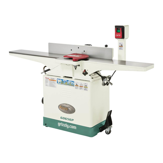
Identification Figure 1. Model G0656 identification. A. Outfeed Table B. Fence C. Cutterhead Guard D. Fence Adjustment Wheel E. Fence Tilt Handle ON/OFF Switch G. Infeed Table H. Fence Tilt Lock Outfeed Table Lock Fence Lock K. Depth Stop Lever Infeed Table Lock M. -
Page 29: Section 1: Safety
SECTION 1: SAFETY For Your Own Safety, Read Instruction Manual Before Operating This Machine The purpose of safety symbols is to attract your attention to possible hazardous conditions. This manual uses a series of symbols and signal words intended to convey the level of impor- tance of the safety messages. - Page 30 WEARING PROPER APPAREL. Do not wear FORCING MACHINERY. Do not force machine. clothing, apparel or jewelry that can become It will do the job safer and better at the rate for entangled in moving parts. Always tie back or which it was designed. cover long hair.
-
Page 31: Additional Safety Instructions For Jointers
Serious cuts, amputation, entanglement, or death can occur from contact with rotating cutterhead or other moving components! Flying chips from cutting operations can cause blindness or eye injuries. Workpieces or inserts/knives thrown by cutterhead (kickback) can strike nearby operator or bystanders with deadly force. To reduce the risk of serious personal injury from these hazards, operator and bystanders MUST completely heed the hazards and warnings below. -
Page 32: Section 2: Circuit Requirements
SECTION 2: CIRCUIT REQUIREMENTS 220V Operation Power Connection Device The type of plug required to connect your machine to power depends on the type of service you cur- rently have or plan to install. We recommend using the plug shown in Figure 2. Serious personal injury could occur if you connect the machine to power before com- GROUNDED... -
Page 33: Section 3: Setup
SECTION 3: SETUP Setup Safety Items Needed for Setup The following items are needed to complete the This machine presents setup process, but are not included with your serious injury hazards machine: to untrained users. Read through this entire manu- Description al to become familiar with •... -
Page 34: Inventory
Inventory The following is a description of the main compo- nents shipped with your machine. Lay the compo- nents out to inventory them. Note: If you can't find an item on this list, check the mounting location on the machine or examine the packaging materials carefully. -
Page 35: Hardware Recognition Chart
Hardware Recognition Chart -12- Model G0656 (Mfg. since 10/07) -
Page 36: Clean Up
Refer to the Machine Data Sheet for the weight this protective coating with a solvent cleaner or and footprint specifications of your machine. citrus-based degreaser such as Grizzly’s G7895 Some residential floors may require additional Citrus Degreaser. To clean thoroughly, some parts reinforcement to support both the machine and must be removed. -
Page 37: Assembly
Assembly With the help of an assistant, lift the jointer onto the stand. Align the mounting holes on the jointer and To assemble the jointer: stand. Carefully lay the stand on its side so you can Secure the jointer to the stand with the access the underside. - Page 38 13. Shift the motor horizontally as needed to Slide the motor upward, and place the V-belt around the cutterhead pulley and the motor align the motor pulley with the cutterhead pul- pulley. ley, then replace the V-belt. 10. Slide the motor down to rest on the V-belt. 14.
- Page 39 19. Using a 2.5mm hex wrench, thread the set screw through the hole in the forked end of the cutterhead guard shaft (Figure 14). Note: Thread the set screw far enough to prevent the guard from being pulled out. Figure 15. Attaching pedestal switch to stand. 24.
-
Page 40: Dust Collection
Dust Collection Setting Outfeed Table Height The outfeed table height MUST be level with the DO NOT operate the Model G0656 without an knives when they are at top-dead-center. If the adequate dust collection system. This jointer outfeed table is set too low, the workpiece will be creates substantial amounts of wood dust tapered from front to back. -
Page 41: Test Run
Recommended —If your outfeed table is correctly set, no adjustments are necessary. Adjustments —If the knife lifts the straightedge off the table or the table is below the straight- edge, adjust the outfeed table height with For your convenience, the adjustments listed the handwheel until the straightedge just below have been performed at the factory and touches a knife at its highest point of rota-... -
Page 42: Section 4: Operations
Regardless of the con- tent in this section, Grizzly Industrial will not be held liable for accidents caused by lack of training. -19-... -
Page 43: Basic Controls
Fence Movement: The fence has a lock that Since the workpiece is held firmly against the keeps it in position (Figure 22). To move the fence as it passes over the cutterhead, the fence controls the angle of the cut. The jointer fence can fence, loosen the lock and turn the fence adjust- be moved 45°... -
Page 44: Stock Inspection & Requirements
Stock Inspection & Only process natural wood fiber through • your jointer. Never joint MDF, particle board, Requirements plywood, laminates, metal, stone, tile, glass, plastic or other synthetically made materials. • Scrape all glue off of boards before joint- Here are some rules to follow when choosing ing. -
Page 45: Squaring Stock
Squaring Stock Surface Planing Squaring stock involves four steps performed The purpose of surface planing on the jointer is in the order below: to make one flat face on a piece of stock (see Figures 26 & 27). This is a necessary step when 1. -
Page 46: Edge Jointing
Edge Jointing To surface plane on the jointer: Read and understand SECTION 1: SAFETY, beginning on Page 6. The purpose of edge jointing is to produce a fin- ished, flat-edged surface (see Figures 28 & 29) Make sure your stock has been inspected that is suitable for joinery or finishing. -
Page 47: Bevel Cutting
Bevel Cutting To edge joint on the jointer: Read and understand SECTION 1: SAFETY, beginning on Page 6. The purpose of bevel cutting is to cut a specific angle into the edge of a workpiece (see Figures Make sure your stock has been inspected 30 &... -
Page 48: Rabbet Cutting
Rabbet Cutting To bevel cut on the jointer: Read and understand SECTION 1: SAFETY, beginning on Page 6. The purpose of rabbet cutting is to remove a section of the workpiece edge (see Figures 32 Make sure your stock has been inspected &... - Page 49 To rabbet cut on the jointer: Note: If your leading hand gets within 4" of the cutterhead, lift it up and over the cutterhead, Read and understand SECTION 1: SAFETY, and place the push block on the portion of the beginning on Page 6.
-
Page 50: Section 5: Accessories
ACCESSORIES SECTION 5: ACCESSORIES H9815—Power Twist V-Belt - ⁄ " x 48" G1753—Jointer Pal Magnetic Knife Gauge ® ® (For HSS & Cobalt Knives) Smooth running with less vibration and noise than solid belts. The Power Twist V-belt can be G1756—Jointer Pal Magnetic Knife Gauge ®... - Page 51 G5562—SLIPIT 1 Qt. Gel H4982—8" HSS Replacement Jointer Knives ® G5563—SLIPIT 12 oz Spray (Set of 4) ® G2871—Boeshield T-9 12 oz Spray ® G2870—Boeshield T-9 4 oz Spray H8029—5 Piece Safety Kit ® H3788—G96 Gun Treatment 12 oz Spray ®...
- Page 52 Finally, a respirator you can look forward Features stainless steel, shock resistant construc- to wearing—at an affordable price! tion and a dust proof display. An absolute treat for the perfectionist! Figure 45. Grizzly Dial Calipers. ® Figure 43. H6175 Power Respirator. -29-...
-
Page 53: Section 6: Maintenance
SECTION 6: MAINTENANCE Always disconnect power Always disconnect power to the machine before to the machine before performing maintenance. lubricating! Failure to do Failure to do this may this may result in serious result in serious person- personal injury. al injury. Schedule Leadscrews: Lubricate with light machine oil as needed. -
Page 54: Cleaning
Fence: Place one or two drops of light machine oil Note: DO NOT completely remove the motor on the fence pivot points (Figure 48) as needed. mount bolts. Figure 48. Fence lubrication locations. Figure 49. Motor bracket fasteners (black arrows); motor mount fasteners (white arrows). Cleaning Remove the V-belt and replace it with a new one. -
Page 55: Section 7: Service
SECTION 7: SERVICE Review the troubleshooting and procedures in this section to fix or adjust your machine if a problem devel- ops. If you need replacement parts or you are unsure of your repair skills, then feel free to call our Technical Support at (570) 546-9663. - Page 56 Motor & Electrical Continued Symptom Possible Cause Possible Solution Machine has vibra- 5. Motor mount loose/broken. 5. Tighten/replace. tion or noisy opera- 6. Machine is incorrectly mounted or sits 6. Relocate machine. tion. unevenly. 7. Motor fan is rubbing on fan cover. 7.
-
Page 57: Inspecting Knives
Inspecting Knives — If the gauge does not sit firmly on the cutterhead and touch the knife edge as described, then reset that knife. (Repeat this inspection with the other knives before The height of the knives can be easily and quickly resetting.) inspected with the knife setting gauge. - Page 58 Remove the cutterhead guard from the table and lower the infeed and outfeed tables as far as they go. This will give you unrestricted access to the cutterhead. Remove the rear access panel to expose the cutterhead pulley. Rotate the cutterhead pulley to give you good access to one of the cutterhead knives.
-
Page 59: Setting Infeed Table
Setting Infeed Table Straightedge The infeed table height is set by calibrating the Outfeed Infeed depth scale, and adjusting the positive stop bolts and depth stop lever. Tools Needed Straightedge ............1 Phillips Head Screwdriver ......... 1 Wrench 14mm ........... 1 Figure 56. -
Page 60: Setting Fence Stops
Setting Fence Stops Adjust the 45˚ inward fence stop set screw until it makes contact with the back of the fence bracket. The fence stops simplify the task of adjusting the Retighten the jam nut loosened in Step 2. fence to 45˚ inward, 90˚, and 45˚ outward (135˚). To set the 90˚... -
Page 61: Adjusting Gibs
Adjusting Gibs To set the 45˚ outward fence stop: Disengage the swing stop (see Figure 23 on Page 20). The function of the table gibs is to eliminate excessive play in the table movement. The gibs Using a sliding bevel adjusted to 135˚, adjust also control how easy it will be to move the tables the fence to the 135˚... -
Page 62: Wiring Diagram
View this page in color at Always use the wiring diagram www.grizzly.com. inside the motor junction box. PUSH BUTTON SWITCH (viewed from behind) (See Figure 65) Ground Figure 65. Switch wiring. - Page 63 Table Parts Breakdown 19-1 19-2 19-3 19-4 19-5 27-1 -40- Model G0656 (Mfg. since 10/07)
- Page 64 Table Parts List REF PART # DESCRIPTION REF PART # DESCRIPTION P0656001 GIB BOLT P0656046 RETAINER P0656002 P0656047 CAP SCREW M5-.8 X 18 P0656003 KNIFE P0656048 SCREW SHAFT P0656004 SET SCREW M6-1 X 10 P0656049 KEY 4 X 4 X 12 P0656005 PULLEY P0656050...
-
Page 65: Fence Parts Breakdown
Fence Parts Breakdown 128 129 -42- Model G0656 (Mfg. since 10/07) - Page 66 Fence Parts List REF PART # DESCRIPTION REF PART # DESCRIPTION P0656101 PHLP HD SCR M6-1 X 12 P0656126 SET SCREW M6-1 X 10 P0656102 FLAT WASHER 6MM P0656127 ADJUST LEVER P0656103 HANDWHEEL P0656128 SMALL BRACKET BLOCK P0656104 BUSHING P0656129 BRACKET BLOCK P0656105 SET SCREW M6-1 X 45...
-
Page 67: Stand Parts Breakdown
Stand Parts Breakdown 226-5 226-1 226-2 226-3 226-6 226-4 226-7 226-8 231-21 231-1 231-20 231-19 231-2 231-18 231-17 231-3 231-16 231-4 231-15 231-14 231-5 231-13 231-12 231-6 231-10 231-11 231-9 231-7 231-8 -44- Model G0656 (Mfg. since 10/07) - Page 68 Stand Parts List PART # DESCRIPTION PART # DESCRIPTION P0656201 CABINET 226-5 P0656226-5 MOTOR JUNCTION BOX P0656202 LOCK NUT M8-1.25 226-6 P0656226-6 S CAPACITOR 200M 250V 1-1/2 X 3-1/2 P0656203 FLAT WASHER 8MM 226-7 P0656226-7 CENTRIFUGAL SWITCH 16MM 3450 P0656204 WHEEL 226-8 P0656226-8...
-
Page 69: Label Placement
MUST maintain the original location and readability of the labels on the machine. If any label is removed or becomes unreadable, REPLACE that label before using the machine again. Contact Grizzly at (800) 523-4777 or www.grizzly.com to order new labels. -46-... - Page 70 Would you recommend Grizzly Industrial to a friend? _____ Yes _____No Would you allow us to use your name as a reference for Grizzly customers in your area? Note: We never use names more than 3 times. _____ Yes _____No 10.
- Page 71 FOLD ALONG DOTTED LINE Place Stamp Here GRIZZLY INDUSTRIAL, INC. P.O. BOX 2069 BELLINGHAM, WA 98227-2069 FOLD ALONG DOTTED LINE Send a Grizzly Catalog to a friend: Name_______________________________ Street_______________________________ City______________State______Zip______ TAPE ALONG EDGES--PLEASE DO NOT STAPLE...
-
Page 72: Warranty And Returns
WARRANTY AND RETURNS Grizzly Industrial, Inc. warrants every product it sells for a period of 1 year to the original purchaser from the date of purchase. This warranty does not apply to defects due directly or indirectly to misuse, abuse, negligence, accidents, repairs or alterations or lack of maintenance.