Chapters
Table of Contents

Related Manuals for Honeywell 057810


Summary of Contents for Honeywell 057810
- Page 1 Montage-Anschluss-Anleitung MB-Secure 4G IP USB Erweiterungsmodul Art.-Nr. 057810 MB-Secure IP USB Kommunikationsmodul Art.-Nr. 057820 800-23827 Rev. B Änderungen vorbehalten 2021-03-17...
- Page 2 Montage-Anschluss-Anleitung / MB-Secure 4G IP USB / IP USB Erweiterungsmodul Sprachen MB-Secure 4G IP USB / IP USB Erweiterungsmodul...... 3 MB-Secure 4G IP USB / IP USB Extension Module...... 31...
-
Page 3: Table Of Contents
Montage-Anschluss-Anleitung / MB-Secure 4G IP USB / IP USB Erweiterungsmodul Inhaltsverzeichnis Sicherheitshinweise....................Allgemeines......................Anwendung..................... Leistungsmerkmale................. Unterstützte Geräte................Platinenaufbau - Übersicht.................. Platinenaufbau - Übersicht..............Verwendung der Anschlussklemmen............. LED USB....................Ethernet-Anschlusskabeltyp..............LED Anzeigen an der Ethernetbuchse........... Montage........................Einbau MB-Secure IP USB Kommunikationsmodul....... Anschluss MB-Secure IP USB Kommunikationsmodul...... -
Page 4: Sicherheitshinweise
Ein zusätzlicher USB-Anschluss steht exklusiv für den Einsatz in Verbindung mit einem 4G Über- tragungsmodul zur Verfügung. Das 4G Übertragungsmodul ist fester Bestandteil der Produktvari- ante Art.-Nr. 057810 und ist nicht als Option erhältlich. Weiterhin stellt das MB-Secure IP USB Kommunikationsmodul eine Ethernet-Schnittstelle zur Ver- fügung und ermöglicht einen zweiten IP-Übertragungsweg für die Aufschaltung und zur Übertra-... -
Page 5: Unterstützte Geräte
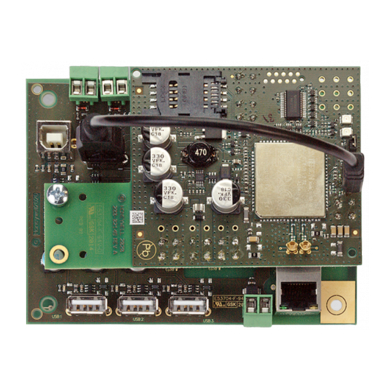
Montage-Anschluss-Anleitung / MB-Secure 4G IP USB / IP USB Erweiterungsmodul Unterstützte Geräte Das MB-Secure IP USB Kommunikationsmodul wird von folgendem Gerät unterstützt: MB-Secure ab Firmwareversion V10.xx, in Verbindung mit IQ PanelControl ab V10.xx. Platinenaufbau - Übersicht Platinenaufbau - Übersicht Erdungsbrücken USB 4 (für 4G Übertragungs- modul) -
Page 6: Ethernet-Anschlusskabeltyp
Montage-Anschluss-Anleitung / MB-Secure 4G IP USB / IP USB Erweiterungsmodul Ethernet-Anschlusskabeltyp Es muss der Kabeltyp Ethernet 10/100BASE-T Twisted Pair, Kategorie 5 oder höherwertig verwendet werden. Handelsbezeichnung z.B. CB-SUTP-3; Cat.5 E, FTP; Cat. 5 E, SFTP. SUTP = Screened Unshielded Twisted Pair. LED Anzeigen an der Ethernetbuchse LED 1 und LED 2. -
Page 7: Anschluss Mb-Secure Ip Usb Kommunikationsmodul
Die folgenden Anschlusshinweise gelten in gleicher Weise für die beiden Module bei Anschluss an die MB-Secure: MB-Secure 4G IP USB Erweiterungsmodul (Art.-Nr. 057810) und MB-Secure IP USB Kommunikationsmodul (Art.-Nr. 057820) Bei Ankopplung über den USB Anschluss darf maximal 1 Modul je Zentrale ver- wendet werden. - Page 8 Montage-Anschluss-Anleitung / MB-Secure 4G IP USB / IP USB Erweiterungsmodul Der Anschluss an die Zentrale MB-Secure erfolgt über die USB-Masterbuchse auf der Rechnerplatine der MB-Secure. Verwenden für Anschluss nur das den Kommu- nikationsmodulen beiliegende spezielle USB-Verbindungska- bel. Dieses Verbindungskabel besitzt eine zusätzlich, heraus- geführte Anschlussleitung für den 0V Anschluss.
-
Page 9: Versorgungsspannung
Reanimationseinheit kann das angeschlossene Übertragungsgerät über das Ein- und Ausschalten der Versorgungsspannung steuern. Dies bewirkt bei GSM-Netzstörungen oder bei einem internen Fehler einen automatischen Reset des GSM-Terminals mit Wiedereinschaltung. 4G Übertragungsmodul als integrierte Komponente bei Art.-Nr. 057810. Die Kommunikation der Reanimationseinheit erfolgt automatisch beim Aufstecken des 4G Übertragungsmodulplatine. -
Page 10: Technische Daten
Secure 0138xx mit der Option IP USB Kommunikationsmodul Art.-Nr. 057820 der Richtlinie 2014/30/EU entspricht. Der vollständige Text der EU-Konformitätserklärung steht auf unserer Homepage https:// www.se- curity.honeywell.de/ im Service/Downloadbereich zum Download bereit. 5.1.1 Anerkennungen VdS-Anerkennung G121801 als Option Art.-Nr. 057820 für die Einbruchmeldezen-... -
Page 11: Übertragungsgerät 4G Ip-Modul
Steht zur Übertragung nur der Funkweg zur Verfügung, kann das 4G IP USB Erweiterungs- modul (Art.-Nr. 057810) überall dort zum Einsatz kommen, wo eine Überwachung des Objekts mit einer Zentrale MB-Secure und die Übertragung von Meldungen gewünscht ist, jedoch kein drahtgebundener Übermittlungsweg für die Meldungsübertragung für die Realisierung zur Verfü-... - Page 12 Montage-Anschluss-Anleitung / MB-Secure 4G IP USB / IP USB Erweiterungsmodul 6.1.2.3 GSM-GPRS-UMTS-LTE Übertragung Mit dem 4G IP USB Erweiterungsmodul (Art.-Nr. 057810) und der Zentrale MB-Secure ist es mög- lich mittels Hilfe des GSM Dienstes GPRS (General Packet Radio Service), UMTS (Universal Mobile Telecommunications System) und LTE (Long Term Evolution) in das Internet einwählen.
- Page 13 Montage-Anschluss-Anleitung / MB-Secure 4G IP USB / IP USB Erweiterungsmodul 6.1.2.5 Konfigurationsbeispiel als redundanter Übertragungsweg GSM-Netz All-IP Ethernet (TCP/IP) Wachunternehmen MB-Secure 4G IP USB Erweiterungsmodul leitungsgebundenes Netz Router Die Grafik zeigt die grundsätzliche Möglichkeit der Aufschaltung auf eine Empfangseinrichtung eines Wachunternehmens. 6.1.2.6 Konfigurationsbeispiel GSM-GPRS Übertragung Intranet / Internet UMTS...
- Page 14 Montage-Anschluss-Anleitung / MB-Secure 4G IP USB / IP USB Erweiterungsmodul 6.1.2.7 Übertragungssystem und Übertragungswege Das 4G IP USB Erweiterungsmodul (Art.-Nr. 057810) beinhaltet ein 4G Übetragungsmodem und ist als Aufsteckplatine ausgeführt. Das 4G IP USB Erweiterungsmodul muss in das entsprechende Systemgehäuse der Zentrale MB-Secure integriert werden. Im Lieferumfang enthalten sind 2 GSM- Antennen, welche zur universellen Montage an den Honeywell ZG-Gehäusetypen geeignet sind.
-
Page 15: Hinweise Zum Mobilfunk Kartenvertrag
Montage-Anschluss-Anleitung / MB-Secure 4G IP USB / IP USB Erweiterungsmodul 6.1.3 Hinweise zum Mobilfunk Kartenvertrag Für den Betrieb des 4G IP USB Erweiterungsmodul (Art.-Nr. 057810) ist ein Mobil- funk Kartenvertrag erforderlich. Dieser Kartenvertrag ist nicht Bestandteil des Kom- plettpaketes. Für den Betreiber des 4G IP USB Erweiterungsmodul besteht daher die Möglichkeit, einen kundenspezifischen Tarif, bei einem Händler seiner Wahl... -
Page 16: Übersicht 4G Ip-Modul
Montage-Anschluss-Anleitung / MB-Secure 4G IP USB / IP USB Erweiterungsmodul Übersicht 4G IP-Modul 6.2.1 Platine 4G Übertragungsmodul SIM-Kartenhalter Anzeige-LED gelb Anzeige-LED grün Jumper Reset (Reanimation) werkseitig gesteckt Mini USB-Buchse (Anschluss zum USB Kommunikationsmodul) Diversity-Antennenanschluss Main-(Haupt)-Antennenanschluss 6.2.2 Montageübersicht Die Abbildung zeigt das MB-Secure 4G IP USB Erweiterungsmodul kompett mit aufgesetztem 4G Übertragungsmodul. - Page 17 Montage-Anschluss-Anleitung / MB-Secure 4G IP USB / IP USB Erweiterungsmodul Montieren Sie zuerst den Montagebolzen (liegt im Zubehörbeutel bei), am IP USB- Kommunikationsmodul (Position im Bild gezeigt). Stecken Sie anschließend das 4G Übertragungsmodul auf das IP USB-Kommunikationsmodul und fixieren Sie mit der beiliegenden Schraube das Modul am Bolzen.
-
Page 18: Antennenmontage
Montage-Anschluss-Anleitung / MB-Secure 4G IP USB / IP USB Erweiterungsmodul 6.2.3 Antennenmontage Dem RFW-4000 GSM/GPRS/4G liegen zwei GSM-Antennen mit Kabel und Stecker bei. Kabellänge der beiliegenden Antenne 50 In Bezug auf den GSM Netzzugang besteht die Möglichkeit 1 oder 2 Antennen zu verwen- den! Die Anzahl der angeschlossenen Antennen muss in der entsprechenden Programmiersoft- ware definiert werden. - Page 19 Montage-Anschluss-Anleitung / MB-Secure 4G IP USB / IP USB Erweiterungsmodul 6.2.3.1 Antennenmontage bei Gehäusen mit Montagewinkel Bei Gehäusen die mit Montagewinkel an der Wand befestigt wer- den, wie zum Beispiel das Gehäuse ZG2 ist die Vorgehens- weise wie folgt: Vor der Gehäusemontage an der Wand beachten: Beide Antennenkabel an der Rückseite des Gehäuses verlegen.
- Page 20 Montage-Anschluss-Anleitung / MB-Secure 4G IP USB / IP USB Erweiterungsmodul Vor der Montage: in den Gehäuseboden die beiden beilie- genden Distanzbolzen einschrauben. Den Gehäuseboden in die Einhängeleiste einhängen, gleichzeitig das Antennenkabel in das Gehäuse einführen. Das Gehäuse mit den Befestigungsschrauben gegen Aus- hängen sichern.
-
Page 21: Hinweis Zum Gsm Antennenanschluss
Montage-Anschluss-Anleitung / MB-Secure 4G IP USB / IP USB Erweiterungsmodul 6.2.4 Hinweis zum GSM Antennenanschluss Antennenkabel nur senkrecht ein-, bzw ausstecken. -
Page 22: Hinweis Zur Leitungsverlegung In Gehäusen
Antenne Antenne Antennen- Anschlusskabel (Kabellänge 50 cm) Antennenkabel im innern MB-Secure 4G IP USB Erweiterungsmodul des Gehäuses so kurz Art.-Nr. 057810 wie möglich verlegen! USB-Verbindungskabel A-Stecker auf Mini B-Stecker zum 4G Übertragungsmodul Netzteil 013960 USB-Verbindungskabel A-Stecker auf B-Stecker zur MB-Secure... -
Page 23: Hinweise Für Installation, Inbetriebnahme Und Sicherheit
Montage-Anschluss-Anleitung / MB-Secure 4G IP USB / IP USB Erweiterungsmodul Hinweise für Installation, Inbetriebnahme und Sicherheit Für einen ordnungsgemäßen Betrieb des 4G USB Erweiterungsmoduls müssen die nachfolgenden Hinweise unbedingt beachtet werden! Während der Projektierungsphase muss zunächst ermittelt werden, welches GSM-Netz im zu überwachenden Objekt zur Verfügung steht. -
Page 24: Inbetriebnahme 4G Ip-Modul
Montage-Anschluss-Anleitung / MB-Secure 4G IP USB / IP USB Erweiterungsmodul Informationen für fest montierte Mobilfunk-Endgeräte Informationen für fest montierte Mobilfunk-Endgeräte - Für Mobilfunkgeräte, die fest mon- tiert sind und einen eigenen Netzanschluss haben, gelten diese zusätzliche Hinweise. Da die Messverfahren für den SAR-Wert nur für eine Nutzung nah am Kopf oder Körper angewen- det werden können, wird die Sicherheit bei fest montierten Mobilfunkgeräten durch Angabe eines Abstandes gewährleistet. -
Page 25: Antenne Und Antennenkabellängen
Montage-Anschluss-Anleitung / MB-Secure 4G IP USB / IP USB Erweiterungsmodul SIM Karte einsetzen Oberteil ca. 90° aufklappen, SIM Karte in die Führungen des Halters einsetzen. SIM card Seitenrichtige Position der SIM Karte beachten. Schliessen SIM Halter in Pfeilrichtung bis zum Einrasten leicht in Pfeilrichtung (LOOK) schieben. - Page 26 Antennensteckers (SMA) auf die Eingangsbuchse des GSM Ter- minals (MMCX), gleichzeitig erfolgt eine mechanische Fixierung der Steckverbindung. Dem 057810 liegt eine Antennenplatine mit Montagewinkel bei. An diese Antennenplatine sind die beiden Kabeladapter der abgesetzen Antennen zu montieren. An diese Kabelad- apter sind die beiden Antennenanschlüsse zu montieren.
-
Page 27: Hinweis Zur Auswahl Der Stromversorgung
Montage-Anschluss-Anleitung / MB-Secure 4G IP USB / IP USB Erweiterungsmodul 6.4.2.3 Montagebeispiel Kabeladapter Abgesetzte Antennen dürfen nur mit der Antennenadapterpla- tine und Montagewinkel verbaut werden. Diese wird an der Position der HUB-Montageschraube an dem USB-HUB fixiert. Der Anschluss des Antennensteckers (SMA) auf die Eingangs- buchse des GSM Terminals (MMCX) erfolgt mittels diesem Kabeladapter. -
Page 28: Übertragung Und Funktion Testen
Montage-Anschluss-Anleitung / MB-Secure 4G IP USB / IP USB Erweiterungsmodul LED grün (2) LED grün -leuchtet: Versorgungsspannung liegt am RFW-4000 an. LED gelb (1) Die gelbe LED zeigt mittels unterschiedlichen Blink-, und Pausenzeiten den aktuellen Zustand des Moduls innerhalb des GSM-Netzes an: LED gelb 500ms ein / 500ms RFW-4000 Terminal Status aus:... -
Page 29: Technische Daten
150 g Abmessungen Platine (B x H x T) 121 x 35 x 90 Konformität Modul Art.-Nr. 057810 ist konform zu EN 50131-3, Grad 3, Klasse II EN50136: bei Verwendung des 4G IP USB Erweiterungs- modules in Verbindung mit der Einbruchmeldezentrale MB Secure wird eine EN50136 konforme Meldungsübertragung... - Page 30 CE Konformität MB Secure - 4G IP USB Erweiterungsmodul Hiermit erklärt die Novar GmbH, dass das Gerät Einbruchmeldezentrale MB Secure 0138xx mit der Option 4G IP USB Erweiterungsmodul Art.-Nr. 057810 der Richtlinie 2014/53/EU entspricht. Der vollständige Text der EU-Konformitätserklärung steht auf unserer Homepage https:// www.se- curity.honeywell.de/ im Service/Downloadbereich zum Download bereit.
- Page 31 Mounting and Connection Instructions MB-Secure 4G IP USB / IP USB Extension Module Contents Safety Instructions....................General Information....................Application....................Performance features................Supported devices.................. Circuit board structure - overview..............Circuit board structure - overview............Use of connection terminals..............LED USB....................Ethernet attachment cable..............LED indicators on the Ethernet socket...........
-
Page 32: Safety Instructions
An additional USB port is available exclusively for use in conjunction with a 4G transmission mod- ule. The 4G transmission module is an integral component of the product variant art. no. 057810 and is not available as a separate option. -
Page 33: Supported Devices
Mounting and Connection Instructions MB-Secure 4G IP USB / IP USB Extension Module Supported devices The MB-Secure IP USB communication module is supported by the following device: MB-Secure from firmware version V10.xx, in conjunction with IQ PanelControl from V10.xx. Circuit board structure - overview Circuit board structure - overview Use of connection terminals The terminals can be connected in two different... -
Page 34: Ethernet Attachment Cable
Mounting and Connection Instructions MB-Secure 4G IP USB / IP USB Extension Module Ethernet attachment cable An Ethernet-type10/100BASE-T Twisted Pair cable, category 5 or higher quality must be used. Trade name for example CB-SUTP-3; cat. 5 E; FTP; CV Cat. 5 E, SFTP. -
Page 35: Connection Mb-Secure Ip Usb Communication Module
The following connection instructions apply in the same way to both modules when connected to the MB-Secure: MB-Secure 4G IP USB extension module (art. no. 057810) and MB-Secure IP USB communication module (art. no. 057820) When connecting via the USB connection, a maximum of one module per control panel may be used. - Page 36 Mounting and Connection Instructions MB-Secure 4G IP USB / IP USB Extension Module The connection to the MB-Secure control panel is made via the USB master socket on the MB- Secure processor board. Only use the special USB connection cable supplied with the communication modules for the connection.
-
Page 37: Power Supply
This will result in an automatic re-set of the GSM terminal with re-start in the event of a failure in the GSM network or an internal failure. 4G transmission module as an integrated component with art. no. 057810. The reanimation unit communicates automatically when the 4G transmission module PCB is attached. -
Page 38: Technical Data
IP USB communication module part no. 057820 complies with Directive 2014/30/EU. The complete text of the EU Declaration of Conformity is available for download on our homepage https:// www.security.honeywell.de/ in the Service/Download area. 5.1.1 Recognitions VdS recognition G121801 as option art. no. 057820 for the MB Secure 0138xx... -
Page 39: Transmission Device 4G Ip Module
When setting up VdS applications, pay attention to VdS specification 2471. 6.1.2.2 Transmission path without redundancy If only radio transmission is available, the 4G IP USB extension module (art. no. 057810) can be used wherever monitoring of the property with an MB-Secure control panel and transmission of messages is desired, but no wired transmission path for message transmission is available for implementation, e.g. - Page 40 Module 6.1.2.3 GSM-GPRS-UMTS-LTE transmission With the 4G IP USB extension module (art. no. 057810) and the MB-Secure control panel, it is pos- sible to dial into the Internet using the GSM service GPRS (General Packet Radio Service), UMTS (Universal Mobile Telecommunications System) and LTE (Long Term Evolution). This enables standing and need-based IP connections to be established to one or more receiving control pan- els.
- Page 41 Mounting and Connection Instructions MB-Secure 4G IP USB / IP USB Extension Module 6.1.2.5 Configuration example as redundant transmission path This graphic shows the basic option of connecting up to a receiver at a security company. 6.1.2.6 Configuration example GSM-GPRS transmission The graphic shows how to implement a standing or need-based IP connection to a receiving control panel.
-
Page 42: Notes About Mobile Network Card Contract
Module 6.1.2.7 Transmission system and transmission paths The 4G IP USB extension module (art. no. 057810) contains a 4G transmission modem and is designed as a plug-on PCB. The 4G IP USB extension module must be integrated into the corre- sponding system housing of the MB-Secure control panel. - Page 43 Mounting and Connection Instructions MB-Secure 4G IP USB / IP USB Extension Module 6.1.3.1 Comments on applying for a mobile network card In general, an application to unlock a mobile network card can be made at any authorised specialist dealer. During the project planning phase, first establish which GSM network is available in the building under surveillance .
-
Page 44: Overview 4G Ip Module
Mounting and Connection Instructions MB-Secure 4G IP USB / IP USB Extension Module Overview 4G IP module 6.2.1 PCB 4G transmission module SIM card holder Indicator LED yellow Indicator LED green Jumper reset (reanimation) plugged in at the factory Mini USB socket (connection to USB communication module) Diversity antenna connection Main antenna connection 6.2.2 Installation overview... - Page 45 Mounting and Connection Instructions MB-Secure 4G IP USB / IP USB Extension Module First mount the mounting bolt (enclosed in the accessory bag), on the IP USB com- munication module (position shown in the picture). Then plug the 4G transmission module onto the IP USB communication module and fix the module to the bolt with the enclosed screw.
-
Page 46: Antenna Installation
Mounting and Connection Instructions MB-Secure 4G IP USB / IP USB Extension Module 6.2.3 Antenna installation The RFW-4000 GSM/GPRS/4G is supplied with two GSM anten- nas with cable and connector. The cable length for the supplied antenna is 50 cm. For GSM network access it is possible to use 1 or 2 antennas. - Page 47 Mounting and Connection Instructions MB-Secure 4G IP USB / IP USB Extension Module 6.2.3.1 Antenna installation for housings with mounting bracket For housings mounted on the wall using a mounting bracket, such as the ZG2 housing the procedure is as follows: Observe the following before mounting the housing on the wall: Lay both antenna cables along the rear wall of the housing.
- Page 48 Mounting and Connection Instructions MB-Secure 4G IP USB / IP USB Extension Module Before mounting: Screw both supplied spacer bolts into the bottom of the housing. Attach the bottom of the housing to the suspension rail, and at the same time insert the antenna cable into the housing.
-
Page 49: Note On The Gsm Antenna Connection
Mounting and Connection Instructions MB-Secure 4G IP USB / IP USB Extension Module 6.2.4 Note on the GSM antenna connection Always insert/remove antenna cable in a vertical position. -
Page 50: Note On Routing Of Wiring In Housings
Mounting and Connection Instructions MB-Secure 4G IP USB / IP USB Extension Module 6.2.5 Note on routing of wiring in housings This figure shows the routing of wiring for the transmission system inside a panel housing: To comply with the requirement of the Low-Voltage Directive, the supply line for the 230 V supply voltage for the power unit mustonly be routed inside the cross- hatched area. -
Page 51: Notes On Installation, Commissioning And Safety
Mounting and Connection Instructions MB-Secure 4G IP USB / IP USB Extension Module Notes on installation, commissioning and safety For proper operation of the 4G USB extension module, the following instructions must be observed!. During the project planning phase, first establish which GSM network is available in the building under surveillance . -
Page 52: Commissioning 4G Ip Module
Mounting and Connection Instructions MB-Secure 4G IP USB / IP USB Extension Module Information for permanently mounted wireless terminals Information for permanently mounted wireless terminal devices - the following additional noti- fications apply for wireless devices in a fixed location with their own power connection. Since the measurement methods for the SAR value can only be applied for use close to the head or body, safety is ensured for permanently mounted mobile radio devices by specifying a dis- tance. -
Page 53: Antenna And Antenna Cable Lengths
Mounting and Connection Instructions MB-Secure 4G IP USB / IP USB Extension Module Insert SIM card Open the upper part approx. 90°, insert the SIM card into the guides of the holder. SIM card Ensure that the SIM card is in the correct position. - Page 54 GSM Terminal (MMCX), while at the same time mechanically securing the plug connection. The 057810 comes with an antenna PCB with mounting bracket. The two cable adapters of the remote antennas are to be mounted on this antenna PCB.
-
Page 55: Note On Selection Of The Power Supply
Mounting and Connection Instructions MB-Secure 4G IP USB / IP USB Extension Module 6.4.2.3 Sample installation for cable adapter Remote antennas may only be installed with the antenna adapter PCB and mounting bracket. The PCB is fixed to the position of the HUB mounting screw on the USB HUB. -
Page 56: Test Transmission And Function
Mounting and Connection Instructions MB-Secure 4G IP USB / IP USB Extension Module LED green (2) LED green - lit: Supply voltage is present on the RFW-4000 . LED yellow (1) The yellow LED uses a range of different flashing and waiting times to display the current status of the module on the GSM network: LED yel- 500ms on / 500ms off: RFW-4000 terminal status... -
Page 57: Technical Data 4G Ip Module
Dimensions of PCB (W x H x T) 121 x 35 x 90 Conformity Module art. no. 057810 conforms to EN 50131-3, grade 3, class II EN50136: When using the 4G IP USB extension module in conjunction with the MB Secure intrusion alarm panel,... - Page 58 CE Conformity MB Secure - 4G IP USB Extension Module Novar GmbH hereby declares that the intrusion alarm panel MB Secure 0138xx with the option 4G IP USB extension module art. no. 057810 complies with Direc- tive 2014/53/EU. The complete text of the EU Declaration of Conformity is available for download on our homepage https:// www.security.honeywell.de/ in the Service/Download area.
- Page 59 Mounting and Connection Instructions MB-Secure 4G IP USB / IP USB Extension Module...
- Page 60 Honeywell Commercial Security Novar GmbH Johannes-Mauthe-Straße 14 800-23827 Rev. B D-72458 Albstadt 2021-03-17 www.honeywell.com/security/de © 2021 Novar GmbH...