Table of Contents
Advertisement
Quick Links
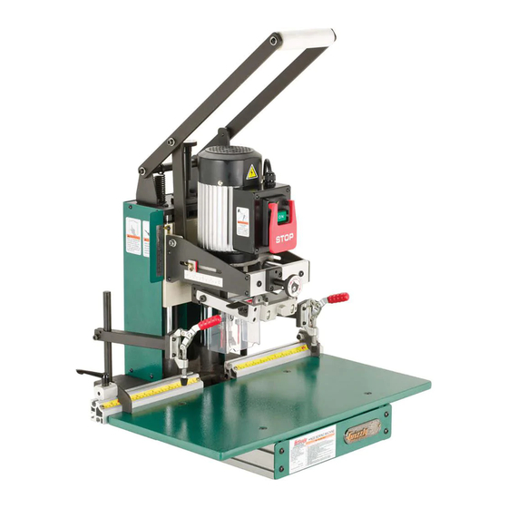
MODEL G0718
HINGE BORING MACHINE
OWNER'S MANUAL
(For models manufactured since 12/10)
COPYRIGHT © MAY, 2011 BY GRIZZLY INDUSTRIAL, INC. REVISED MAY, 2018 (BL)
WARNING: NO PORTION OF THIS MANUAL MAY BE REPRODUCED IN ANY SHAPE
OR FORM WITHOUT THE WRITTEN APPROVAL OF GRIZZLY INDUSTRIAL, INC.
#CRBLJBTS13651 PRINTED IN TAIWAN
V1.05.18
Advertisement
Table of Contents

Related Manuals for Grizzly G0718


Summary of Contents for Grizzly G0718
- Page 1 OWNER'S MANUAL (For models manufactured since 12/10) COPYRIGHT © MAY, 2011 BY GRIZZLY INDUSTRIAL, INC. REVISED MAY, 2018 (BL) WARNING: NO PORTION OF THIS MANUAL MAY BE REPRODUCED IN ANY SHAPE OR FORM WITHOUT THE WRITTEN APPROVAL OF GRIZZLY INDUSTRIAL, INC.
- Page 2 This manual provides critical safety instructions on the proper setup, operation, maintenance, and service of this machine/tool. Save this document, refer to it often, and use it to instruct other operators. Failure to read, understand and follow the instructions in this manual may result in fire or serious personal injury—including amputation, electrocution, or death.
-
Page 3: Table Of Contents
Table of Contents INTRODUCTION ..........2 SECTION 4: OPERATIONS ......21 Manual Accuracy ........... 2 Basic Controls ..........21 Contact Info............ 2 Disabling & Locking Switch......22 Machine Description ........2 Setup Overview..........22 Identification ........... 3 Operation Overview ........22 Machine Data Sheet ........ -
Page 4: Introduction
Machine Description and it helps us determine if updated documenta- tion is available for your machine. The Model G0718 is a production machine designed for drilling and installing European-style hinges in cabinet doors. Grizzly offers are a number of different boring... -
Page 5: Identification
Identification Figure 1. Model G0718 controls and features. A. Fence Extension w/Left Scale Throat Position Scale B. Throat Adjustment Knob K. Table Support w/Hold-Down Track C. ON/OFF Switch Assembly Hold-Down Base & Arm Assembly D. Drive Motor M. 4" Dust Port E. -
Page 6: Machine Data Sheet
Machine Data Sheet macHine daTa SHeeT © Grizzly Industrial, Inc. • Customer Service: (800) 523-4777 • Website: www.grizzly.com model G0718 HinGe borinG macHine Product Dimensions: Weight ................................... 154 lbs. Width (side-to-side) x Depth (front-to-back) x Height ..................29 x 25 x 36-5/8 in. - Page 7 Customer Cleanup and Assembly Time ........................30 Minutes Features: Swing boring head tolerance +/- 0.2mm Downfeed stroke scale position indicator Rear fence scale position indicator 28" extension fence Manual stroke operation Model G0718 Page 2 of 2 Model G0718 (Mfd. Since 12/10)
-
Page 8: Section 1: Safety
Everyday ery. Never operate under the influence of drugs or eyeglasses are NOT approved safety glasses. alcohol, when tired, or when distracted. Model G0718 (Mfd. Since 12/10) - Page 9 Make sure they are properly installed, you experience difficulties performing the intend- undamaged, and working correctly BEFORE ed operation, stop using the machine! Contact our operating machine. Technical Support at (570) 546-9663. Model G0718 (Mfd. Since 12/10)
-
Page 10: Additional Safety For Boring Machines
Failure to do so could result in serious per- risk of operator injury. If normal safety pre- sonal injury, damage to equipment, or poor cautions are overlooked or ignored, serious work results. personal injury may occur. Model G0718 (Mfd. Since 12/10) -
Page 11: Section 2: Power Supply
Nominal Voltage ..208V, 220V, 230V, 240V meets the specified circuit requirements. Cycle ............60 Hz Phase ........... Single-Phase Power Supply Circuit ......15 Amps Plug/Receptacle ......NEMA 6-15 Model G0718 (Mfd. Since 12/10) -
Page 12: Grounding Requirements
The plug must only be inserted into a matching receptacle (see following figure) that is properly installed and grounded in accordance with all local codes and ordinances. -10- Model G0718 (Mfd. Since 12/10) -
Page 13: Voltage Conversion
Loosen the screws indicated in Figure 5. Motor This section shows how to convert the Model G0718 from 110V to 220V. The plug needed for this conversion can be purchased at any local Loosen hardware store or electrical supply store. -
Page 14: Section 3: Setup
IMPORTANT: Save all packaging materials until you are completely satisfied with the machine and have resolved any issues between Grizzly or the shipping agent. You MUST have the original pack- aging to file a freight claim. It is also extremely helpful if you need to return your machine later. -
Page 15: Inventory
Repeat Steps 2–3 as necessary until clean, then coat all unpainted surfaces with a quality Figure 7. Inventory. metal protectant to prevent rust. NOTICE Avoid chlorine-based solvents, such as acetone or brake parts cleaner, that may damage painted surfaces. -13- Model G0718 (Mfd. Since 12/10) -
Page 16: Site Considerations
Only install in an Shadows, glare, or strobe effects that may distract access restricted location. or impede the operator must be eliminated. 28" 57" Power Supply Dust Port " " Figure 8. Minimum working clearances. -14- Model G0718 (Mfd. Since 12/10) -
Page 17: Lifting & Placing
Another option is a "direct mount" (see example below) where the machine is secured directly to the workbench with lag screws and washers. Lag Screw Flat Washer Machine Base Workbench Figure 10. "Direct Mount" setup. -15- Model G0718 (Mfd. Since 12/10) -
Page 18: Assembly
Extension Screw Fence Grizzly offers a number of boring heads for this Rods machine (refer to Page 32 for more details). The boring head must be installed before performing the Test Run procedure. To choose the correct boring head, refer to Selecting Boring Head on Page 24. - Page 19 Install the dust port. cap screws at the inside holes shown in Figure 16. Figure 14. Dust port installed. M6-1 x 65 Cap Screws (3 of 4 Shown) Figure 16. Securing boring head to machine. -17- Model G0718 (Mfd. Since 12/10)
- Page 20 Knurled Knobs M6-1 x 45 Cap Screw (1 of 2 Shown) M6-1 x 55 Cap Screw (1 of 2 Shown) Figure 18. Securing swing arm assembly. Figure 20. Clear guard installed. -18- Model G0718 (Mfd. Since 12/10)
-
Page 21: Dust Collection
After you have completed all previous setup instructions and circuit requirements, the machine is ready to be connected to the power supply. DO NOT operate the Model G0718 with- out an adequate dust collection system. To avoid unexpected startups or property dam-... -
Page 22: Test Run
Always disconnect the machine from power when investigating or correcting potential problems. Turn the machine OFF. Insert the switch disabling pin through the green ON button, as shown in Figure 23. -20- Model G0718 (Mfd. Since 12/10) -
Page 23: Section 4: Operations
Regardless of the content in this section, workpieces at the same location. Grizzly Industrial will not be held liable for accidents caused by lack of training. Hold-Down Clamp: Secures the workpiece firmly against the table and fence. Adjusts... -
Page 24: Disabling & Locking Switch
ON/START button, as shown. Locking the switch in this manner can To set up the Model G0718, the operator does prevent unauthorized operation of the machine, the following: which is especially important if the machine is not stored inside an access-restricted building. -
Page 25: Hold-Down Clamps
Note: If the foot presses too loose or too tight against the board, loosen the hex nut above the foot, and adjust the foot as needed, then tighten the hex nut against the foot. -23- Model G0718 (Mfd. Since 12/10) -
Page 26: Boring Head Setup
Figure 28. Dimensions required for matching hinge to boring head. DISCONNECT BORING MACHINE FROM POWER! The Model G0718 accepts two pilot bits and a cup bit, as shown in Figure 29. Remove the clear guard and the boring bits. Pivot the swing arm up. -
Page 27: Installing & Adjusting Boring Bits
Hinge Installed (3 of 4 Shown) Figure 32. Removing inner cap screws. Figure 34. Hinge bits set even, holes drilled in workpiece, hinge installed. Install the new boring head in the reverse order or removal. -25- Model G0718 (Mfd. Since 12/10) -
Page 28: Headstock Setup
Before using the Model G0718 to drill holes in an Loosen the set screws on all the chucks (see actual cabinet door, you need to set up the boring Figure 35). -
Page 29: Drilling Depth
Note: If the hinge requires the pilot holes to be deeper or shallower than the cup hole, adjust the individual bit depths as necessary at this time (refer to Installing Boring Bits on Page 25). -27- Model G0718 (Mfd. Since 12/10) -
Page 30: Operation
Then retest using a different place on the board or on a different board until the hinge does fit. Figure 42. Swing arm positioned over cup hole. -28- Model G0718 (Mfd. Since 12/10) -
Page 31: Fence Stop Setup
(see Figure 43). The Model G0718 can bore holes for 2-hinge, 3-hinge, or 4-hinge doors, using the included fence stops and fences. (The extension fence is Swing Arm typically only used for 3- and 4-hinge doors.) -
Page 32: Two-Hinge Door
Accessories on Page 32). If you plan to pro- Stop cess a large number of cabinet doors, having Hole 3 three fence stops in preset positions will quicken Clamp Clamp the production process. -30- Model G0718 (Mfd. Since 12/10) -
Page 33: Four-Hinge Door
Four-Hinge Door The Model G0718 can bore four hinge cup holes in a cabinet door up to 63 ⁄ " long using the stan- Figure 47 demonstrates the sequential process of dard extension fence and two included flip stops. boring holes for a four-hinge door. -
Page 34: Section 5: Accessories
48mm cause machine to malfunction, resulting in serious personal injury or machine damage. To reduce this risk, only install accessories recommended for this machine by Grizzly. NOTICE Refer to our website or latest catalog for additional recommended accessories. Figure 49. T23281 Boring Pattern Dimensions. - Page 35 Model We've hand picked a selection of commonly used G0718. It also allows you to set fence stops for dust collection components for machines with 4" longer doors and provides additional support.
- Page 36 Also compatible with safety glasses! Figure 58. Recommended products for protect- ing unpainted cast iron/steel part on machinery. Figure 60. Half-mask respirator with disposable cartridge filters. www.grizzly.com 1-800-523-4777 order online at or call -34- Model G0718 (Mfd. Since 12/10)
-
Page 37: Section 6: Maintenance
Cleaning Always disconnect the machine from power Cleaning the Model G0718 is relatively easy. before performing main- Vacuum excess wood chips and sawdust, and tenance. Failure to do wipe off the remaining dust with a dry cloth. If any this may result in serious resin has built up, use a resin dissolving cleaner personal injury. -
Page 38: Headstock Slides
Turn the adjustment knobs to move the shafts through the entire range of motion to evenly distribute the oil. Grease Fitting Figure 64. Grease fitting location. -36- Model G0718 (Mfd. Since 12/10) -
Page 39: Section 7: Service
5. Motor or boring head bearings are at fault. 5. Replace bearings. 6. Centrifugal switch is at fault. 6. Adjust/replace centrifugal switch. 7. Motor has overheated. 7. Clean off motor, let cool, and reduce workload. 8. Motor is at fault. 8. Test/repair/replace. -37- Model G0718 (Mfd. Since 12/10) -
Page 40: Operation
1. Adjust set screw on cup bit out so it drills deeper. insert into cup hole. Workpiece 1. Hold-down clamp feet are not tight 1. Adjust hold-downs (see Page 23). moves when enough against the workpiece. secured with hold-downs. -38- Model G0718 (Mfd. Since 12/10) -
Page 41: Section 8: Wiring
Technical Support at (570) 546-9663. The photos and diagrams included in this section are best viewed in color. You can view these pages in color at www.grizzly.com. -39- Model G0718 (Mfd. Since 12/10) -
Page 42: Wiring Diagram
Figure 65. Electrical overview. Rd Rd 110 VAC 5-15 Plug Neutral Ground Machine Re-wired for 220V Motor Switch Re-wired for 220V 220 VAC 6-15 Plug Rd Rd (As Recommended) Ground READ ELECTRICAL SAFETY -40- Model G0718 (Mfd. Since 12/10) ON PAGE 39! -
Page 43: Section 9: Parts
SECTION 9: PARTS Body BUY PARTS ONLINE AT GRIZZLY.COM! -41- Model G0718 (Mfd. Since 12/10) Scan QR code to visit our Parts Store. - Page 44 Please Note: We do our best to stock replacement parts whenever possible, but we cannot guarantee that all parts shown here are available for purchase. Call (800) 523-4777 or visit our online parts store at www.grizzly.com to check for availability.
-
Page 45: Table
LEFT FRONT LONGITUDINAL SCALE P0718173 FLAT HD SCR M6-1 X 16 P0718142 FLAT WASHER 5MM P0718174 FENCE CONNECTING ROD P0718143 REAR LONGITUDINAL FENCE BUY PARTS ONLINE AT GRIZZLY.COM! -43- Model G0718 (Mfd. Since 12/10) Scan QR code to visit our Parts Store. -
Page 46: Headstock
RIGHT BIT ARBOR P0718213 L-BRACKET P0718229 SET SCREW M5-.8 X 5 P0718214 PIVOT ARM EXTENSION SPRING * Optional Equipment Purchased Separately BUY PARTS ONLINE AT GRIZZLY.COM! -44- Model G0718 (Mfd. Since 12/10) Scan QR code to visit our Parts Store. -
Page 47: Handle
CAP SCREW M8-1.25 X 16 P0718322 CAP SCREW M8-1.25 X 50 P0718311 LOCK WASHER 8MM P0718323 DUST PORT 4" P0718312 HEX NUT M8-1.25 BUY PARTS ONLINE AT GRIZZLY.COM! -45- Model G0718 (Mfd. Since 12/10) Scan QR code to visit our Parts Store. -
Page 48: Machine Labels
Safety labels help reduce the risk of serious injury caused by machine hazards. If any label comes off or becomes unreadable, the owner of this machine MUST replace it in the original location before resuming operations. For replacements, contact (800) 523-4777 or www.grizzly.com. BUY PARTS ONLINE AT GRIZZLY.COM! -46- Model G0718 (Mfd. - Page 49 Would you recommend Grizzly Industrial to a friend? _____ Yes _____No Would you allow us to use your name as a reference for Grizzly customers in your area? Note: We never use names more than 3 times. _____ Yes _____No 10.
- Page 50 FOLD ALONG DOTTED LINE Place Stamp Here GRIZZLY INDUSTRIAL, INC. P.O. BOX 2069 BELLINGHAM, WA 98227-2069 FOLD ALONG DOTTED LINE Send a Grizzly Catalog to a friend: Name_______________________________ Street_______________________________ City______________State______Zip______ TAPE ALONG EDGES--PLEASE DO NOT STAPLE...
-
Page 51: Warranty And Returns
WARRANTY AND RETURNS Grizzly Industrial, Inc. warrants every product it sells for a period of 1 year to the original purchaser from the date of purchase. This warranty does not apply to defects due directly or indirectly to misuse, abuse, negligence, accidents, repairs or alterations or lack of maintenance.