Table of Contents
Advertisement
Quick Links
Advertisement
Table of Contents

Related Manuals for Draytek VigorAP 802


Summary of Contents for Draytek VigorAP 802
- Page 2 VigorAP 802 802.11ac Access Point User’s Guide Version: 1.1 Firmware Version: V1.3.4 Date: May 12, 2020...
- Page 3 Web registration is preferred. You can register your Vigor modem via http://www.draytek.com. Owner Firmware & Tools Due to the continuous evolution of DrayTek technology, all modems will be regularly upgraded. Please consult the DrayTek web site for more information on newest firmware, tools and documents. Updates http://www.draytek.com...
-
Page 4: Table Of Contents
Table of Contents Chapter I Installation ..............................VI I-1 Introduction....................................1 I-1-1 LED Indicators and Connectors..........................3 I-2 Hardware Installation...................................5 I-3 Network IP Configuration ................................6 I-3-1 Windows 7 IP Address Setup .............................6 I-4 Accessing to Web User Interface ..............................8 I-5 Changing Password ................................... 11 I-6 Dashboard .................................... - Page 5 V-4 Pinging the Device .................................. 127 V-4-1 For Windows ................................127 V-4-2 For Mac Os (Terminal) ............................127 V-5 Backing to Factory Default Setting ............................129 V-5-1 Software Reset............................... 129 V-5-2 Hardware Reset..............................130 V-6 Contacting DrayTek ................................131 Index ....................................... 132...
-
Page 6: Chapter I Installation
Chapter I Installation... -
Page 7: Introduction
Besides, the software installation can be completed easily by using a mobile phone to scan the QR code on the front side of VigorAP device. The DrayTek Wireless APP will guide the users to configure the device in AP or Range Extender mode just with several steps. - Page 8 Follow the instructions given in this user manual, you can complete the setup procedure and release the power of this access point all by yourself!
-
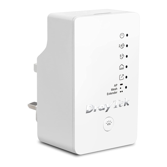
Page 9: I-1-1 Led Indicators And Connectors
I-1-1 LED Indicators and Connectors Before you use the Vigor modem, please get acquainted with the LED indicators and connectors first. Status Explanation The system is not ready or is failed. Blinking Slowly: The system is ready and can work normally. Quickly: The system is booting up or resetting to the Factory Default value. - Page 10 Button Factory Reset Press it for more than 15 seconds. When the ACT LED flashes rapidly, release the button. Mesh Node This AP is configured with Mesh Node mode. Mode Press it for more than 2 seconds. Within 5 seconds, the AP is trying to connect to the mesh network.
-
Page 11: Hardware Installation
I-2 Hardware Installation This section will guide you to install the AP through hardware connection and configure the settings through web browser. Before starting to configure the device, you have to connect your device correctly. Plug VigorAP into a power outlet. Use a twisted-pair cable with RJ-45 plugs at both ends, and plug into Ethernet device (e.g., Vigor router) and Ethernet port of VigorAP. -
Page 12: Network Ip Configuration
I-3 Network IP Configuration After the network connection is built, the next step you should do is setup VigorAP 802 with proper network parameters, so it can work properly in your network environment. Before you can connect to the access point and start configuration procedures, your computer must be able to get an IP address automatically (use dynamic IP address). - Page 13 Under the General tab, click Use the following IP address. Then input the following settings in respective field and click OK when finish. IP address: 192.168.1.9 Subnet Mask: 255.255.255.0...
-
Page 14: Accessing To Web User Interface
You may either simply set up your computer to get IP dynamically from the router or set up the IP address of the computer to be in the same subnet as the IP address of VigorAP 802. If there is no DHCP server on the network, then VigorAP 802 will have an IP address of ... - Page 15 For the first time accessing VigorAP, the Quick Start Wizard for configuring wireless settings will appear as follows. Refer to Section I-7 Quick Start Wizard for detailed information. If VigorAP has been configured previously, the Dashboard of VigorAP will appear as follows:...
- Page 16 The web page can be logged out by clicking Log Out on the top right of the web page. Or, logout the web user interface according to the chosen condition. The default setting is Auto Logout, which means the web configuration system will logout after 5 minutes without any operation.
-
Page 17: Changing Password
I-5 Changing Password Please change the password for the original security of the modem. Go to System Maintenance page and choose Administration Password. Enter the new login password on the field of Password. Then click OK to continue. Now, the password has been changed. Next time, use the new password to access the Web User Interface for this modem. -
Page 18: Dashboard
I-6 Dashboard Dashboard shows system status including the number of client connected, throughput, gateway, physical connection status, radio (2.4GHz / 5GHz) status, backhaul network, recent activities, wireless network usage, and so on. Click Dashboard from the main menu on the left side of the main page. -
Page 19: Quick Start Wizard
I-7 Quick Start Wizard Quick Start Wizard will guide you to configure 2.4G wireless setting, 5G wireless setting and other corresponding settings for Vigor Access Point step by step. Available operation mode includes: Access Point Mesh Node Range Extender ... -
Page 20: I-7-1 Settings For Access Point
In the following page, configure the settings for wireless LAN (for both 2.4GHz and 5GHz) and click Next Step. Available settings are explained as follows: Item Description WiFi Name Display the default name with the rule of DrayTek-last three MAC address. - Page 21 Wi-Fi service for its guests for one hour every day. 2nd WiFi Name - Set a name for VigorAP 802 which can be identified and connected by wireless guest. 2nd WiFi Password - Set 8~63 ASCII characters which can be used for logging into VigorAP 802 by wireless guest.
- Page 22 Admin Password Enter a new password. Confirm Enter the new password again for confirmation. Password A summary of settings configuration will be shown on screen. Click Finish.
-
Page 23: I-7-2 Settings For Mesh Node
I-7-2 Settings for Mesh Node Choose Mesh Node as the operation mode and click Next Step. A summary of settings configuration will be shown on screen. Click Finish. -
Page 24: I-7-3 Settings For Range Extender
I-7-3 Settings for Range Extender Choose Range Extender as the operation mode and click Next Step. Configure the settings for wireless LAN (for both 2.4GHz and 5GHz) and click Next Step. Available settings are explained as follows: Item Description... - Page 25 Wi-Fi service for its guests for one hour every day. 2nd WiFi Name - Set a name for VigorAP 802 which can be identified and connected by wireless guest. 2nd WiFi Password - Set 8~63 ASCII characters or 8~63 ASCII characters which can be used for logging into VigorAP 802 by wireless guest.
- Page 26 Change the default password for such device with new value. Then click Next Step. Available settings are explained as follows: Item Description Admin Password Enter a new password. Confirm Enter the new password again for confirmation. Password In the following page, click Search to find out neighboring access point. When all the available access points appear on the page, click the one you want to connect.
- Page 27 Available settings are explained as follows: Item Description SSID/Security Key Once the access point specified above, the name / security key of the AP will be shown automatically in these fields. Channel Means the channel frequency of the wireless LAN. You may switch channel if the selected channel is under serious interference.
- Page 28 A summary of settings configuration will be shown on screen. Click Finish.
-
Page 29: Chapter Ii Connectivity
Chapter II Connectivity... -
Page 30: Operation Mode
II-1 Operation Mode This page provides several available modes for you to choose for different conditions. Click any one of them and click OK. The system will configure the required settings automatically. Available settings are explained as follows: Item Description This mode allows wireless clients to connect to access point and exchange data with the devices connected to the wired network. - Page 31 Note: The Wireless LAN settings will be changed according to the Operation Mode selected here. For the detailed information, please refer to the section of Wireless LAN.
-
Page 32: General Concepts For Wireless Lan (2.4Ghz/5Ghz)
VigorAP 802 is a highly integrated wireless local area network (WLAN) for 5 GHz 802.11ac or 2.4/5 GHz 802.11n WLAN applications. It supports channel operations of 20/40 MHz at 2.4 GHz and 20/40/80 MHz at 5 GHz. VigorAP 802 can support data rates up to 867 MBps in 802.11ac 80 MHz channels. - Page 33 Start PBC button or using PIN Code. On the side of VigorAP 802 series which served as an AP, press WPS button once on the front panel of VigorAP 802 or click Start PBC on web configuration interface. On the side of a station with network card installed, press Start PBC button of network card.
-
Page 35: Wireless Lan (2.4Ghz/5Ghz) Settings For Ap Mode
II-3 Wireless LAN (2.4GHz/5GHz) Settings for AP Mode When you choose AP as the operation mode, the Wireless LAN menu items will include General Setup, Security, Access Control, WPS, Advanced Setting, AP Discovery, Bandwidth Management, Airtime Fairness, Station Control, Roaming, Band Steering and Station List. ... -
Page 36: Ii-3-1 General Setup
II-3-1 General Setup By clicking the General Setup, a new web page will appear so that you could configure the SSID, the wireless channel and WDS. Please refer to the following figure for more information. Available for 5GHz Access Point Mode Available settings are explained as follows: Item Description... - Page 37 Internet through Vigor device. The number you can set is from 3 to 64. Mode At present, VigorAP 802 can connect to 11b only, 11g only, 11n only, Mixed (11b+11g), Mixed (11g+11n) and Mixed (11b+11g+11n) stations simultaneously. Simply choose Mixed (11b+11g+11n) mode.
- Page 38 by default, it means disabling the VLAN function for the SSID. PHY Mode Data will be transmitted via HTMIX mode. Each access point should be setup to the same Phy Mode for connecting with each other. Security Select WEP, TKIP or AES as the encryption algorithm. Type 8~63 ASCII characters, such as 012345678..(or 64 Hexadecimal digits leading by 0x, such as "0x321253abcde...").
-
Page 39: Ii-3-2 Security
PSK (Pre-Shared Key) entered manually in this field below or automatically negotiated via 802.1x authentication. WEP/802.1x - The built-in RADIUS client feature enables VigorAP 802 to assist the remote dial-in user or a wireless station and the RADIUS... - Page 40 remote access authentication for network management. The WPA encrypts each frame transmitted from the radio using the key, which either PSK (Pre-Shared Key) entered manually in this field below or automatically negotiated via 802.1x authentication. Select WPA, WPA2 or Auto as WPA mode. WPA/802.1x - The WPA encrypts each frame transmitted from the radio using the key, which either PSK (Pre-Shared Key) entered manually in this field below or automatically negotiated via 802.1x...
- Page 41 Available settings are explained as follows: Item Description IP Address Enter the IP address of external RADIUS server. Port The UDP port number that the external RADIUS server is using. The default value is 1812, based on RFC 2138. Shared Secret The external RADIUS server and client share a secret that is used to authenticate the messages sent between them.
-
Page 42: Ii-3-3 Access Control
Choose Activate MAC address filter to type in the MAC addresses for other clients in the network manually. Choose Blocked MAC address filter, so that all of the devices with the MAC addresses listed on the MAC Address Filter table will be blocked and cannot access into VigorAP 802. -
Page 43: Ii-3-4 Wps
MAC Address Filter Display all MAC addresses that are edited before. Client’s MAC Address - Manually enter the MAC address of wireless client. Add - Add a new MAC address into the list. Delete - Delete the selected MAC address in the list. Edit - Edit the selected MAC address in the list. -
Page 44: Ii-3-5 Advanced Setting
Type the PIN code specified in wireless client you wish to connect, and PinCode click Start PIN button. Both ACT and 2.4G WLAN LEDs on VigorAP 802 will blink quickly when WPS is in progress. It will return to normal condition after two minutes. - Page 45 Item Description Channel Width 20 MHz- The device will use 20MHz for data transmission and receiving between the AP and the stations. Auto 20/40 MHz–The AP will scan for nearby wireless AP, and then use 20MHz if the number of AP is more than 10, or use 40MHz if it's not.
- Page 46 However, some wireless stations will detect / scan the country code to prevent conflict occurred. If conflict is detected, wireless station will be warned and is unable to make network connection. Therefore, changing the country code to ensure successful network connection will be necessary for some clients.
-
Page 47: Ii-3-6 Ap Discovery
II-3-6 AP Discovery VigorAP 802 can scan all regulatory channels and find working APs in the neighborhood. Based on the scanning result, users will know which channel is clean for usage. Also, it can be used to facilitate finding an AP for a WDS link. Notice that during the scanning process (about 5 seconds), no client is allowed to connect to VigorAP. -
Page 48: Ii-3-7 Wds Ap Status
II-3-7 WDS AP Status VigorAP 802 can display the status such as MAC address, physical mode, power save and bandwidth for the working AP connected with WDS. Click Refresh to get the newest information. It is available for wireless LAN (5GHz) only. -
Page 49: Ii-3-9 Airtime Fairness
Take the following figure as an example, both Station A(11g) and Station B(11n) transmit data packets through VigorAP 802. Although they have equal probability to access the wireless channel, Station B(11n) gets only a little airtime and waits too much because Station A(11g) spends longer... - Page 50 To improve this problem, Airtime Fairness is added for VigorAP 802. Airtime Fairness function tries to assign similar airtime to each station (A/B) by controlling TX traffic. In the following figure, Station B(11n) has higher probability to send data packets than Station A(11g). By this way, Station B(fast rate) gets fair airtime and it's speed is not limited by Station A(slow rate).
-
Page 51: Ii-3-10 Station Control
Triggering Client Number –Airtime Fairness function is applied only when active station number achieves this number. After finishing this web page configuration, please click OK to save the settings. Note: Airtime Fairness function and Bandwidth Limit function should be mutually exclusive. So their webs have extra actions to ensure these two functions are not enabled simultaneously. - Page 52 Available settings are explained as follows: Item Description SSID Display the SSID that the wireless station will use it to connect with Vigor router. Enable Check the box to enable the station control function. Connection Time / Use the drop down list to choose the duration for the wireless client Reconnection Time connecting /reconnecting to Vigor device.
-
Page 53: Ii-3-11 Roaming
VigorAP 802 will terminate the network connection for that wireless station. Minimum RSSI - When the signal strength of the wireless station is below the value (dBm) set here and adjacent AP (must be DrayTek AP and support such feature too) with higher signal strength value... - Page 54 (defined in the field of With Adjacent AP RSSI over) is detected by VigorAP 802, VigorAP 802 will terminate the network connection for that wireless station. Later, the wireless station can connect to the adjacent AP (with better RSSI). With Adjacent AP RSSI over – Specify a value as a threshold.
-
Page 55: Ii-3-12 Band Steering (For Wireless Lan (2.4Ghz))
II-3-12 Band Steering (for Wireless LAN (2.4GHz)) Band Steering detects if the wireless clients are capable of 5GHz operation, and steers them to that frequency. It helps to leave 2.4GHz band available for legacy clients, and improves users experience by reducing channel utilization. If dual-band is detected, the AP will let the wireless client connect to less congested wireless LAN, such as 5GHz to prevent from network congestion. - Page 56 Therefore, when the signal strength is below the value set here while the wireless station connecting to VigorAP 802, VigorAP will allow the client to connect to 2.4GHz network. After finishing this web page configuration, please click OK to save the settings.
- Page 57 Below shows how Band Steering works.
- Page 58 How to Use Band Steering? Open Wireless LAN(2.4GHz)>>Band Steering. Check the box of Enable Band Steering and use the default value (15) for check time setting. Click OK to save the settings. Open Wireless LAN (2.4GHz)>>General Setup and Wireless LAN (5GHz)>> General Setup. Configure SSID as ap802-BandSteering for both pages.
- Page 59 Security as 12345678 for both pages. Click OK to save the settings. Same value for 2.4GHz and 5GHz Now, VigorAP 802 will let the wireless clients connect to less congested wireless LAN, such as 5GHz to prevent from network congestion.
-
Page 60: Ii-3-13 Station List
II-3-13 Station List Station List provides the information related to the number of clients connecting to VigorAP, used bandwidth and the statistics of the AP device OS. Besides, users can create access control policies, device objects and set black & white list for II-3-13-1 Connected Number This page lists the graph for the number of wireless stations connected to this Access Point with different time phases. - Page 62 II-3-13-3 Clients List The client list displays all the stations connecting to VigorAP. Available settings are explained as follows: Item Description +Access Control It is available after choosing one of the entries (clients) on Clients List. Wireless LAN - Specify the bandwidth for the access control list. SSID Policy - Set the policy for each SSID as black list or white list or disable.
- Page 63 control. Apply to SSID - Check All to make the device apply the policies to all SSIDs. Or select the one(s) to make the device apply the policies to the selected SSIDs. Close - Exit this page without saving any changes. Save changes - Save the changes and exit this page.
- Page 64 II-3-13-4 Block List This page displays information of the stations under block list. Available settings are explained as follows: Item Description Device Object list Click it to open the Device Object List dialog for reference. Name / MAC Display the host name / MAC Address for the connecting client. SSID Display the SSID that the wireless client connects to.
- Page 65 II-3-13-5 White List This page displays general information of the stations under white list. Available settings are explained as follows: Item Description Device Object list Click it to open the Device Object List dialog for reference. Name / MAC Display the host name / MAC Address for the connecting client. SSID Display the SSID that the wireless client connects to.
-
Page 66: Mesh Settings For Mesh Node Mode
II-4 Mesh Settings for Mesh Node Mode When you choose Mesh Node as the operation mode, the Mesh menu with the settings of Mesh Setup, Mesh Status, Mesh Discovery and Configuration Sync will be shown on the screen. Please note that, within VigorMesh network, the total number allowed for mesh nodes is 8 (including the mesh root) ... - Page 67 For the mesh group set within VigorMesh network, It must be composed by “1” Mesh Root and “0~7” mesh nodes (Roaming) Normally members in a mesh group use the same Wireless SSID/security (Add) Only the mesh root can add a new mesh node into the mesh group ...
-
Page 68: Ii-4-1 Mesh Setup
Important: The VigorAP 802 can be ONLY set as a "mesh node" to be used with a Mesh Root (e.g., VigorAP 903). II-4-1 Mesh Setup Such page can determine the role of the VigorAP. Basically, VigorAP can be used as a mesh node only. - Page 69 Role Mesh Node – As a mesh node, the VigorAP can pass the wireless connection signal to other mesh node or a remote device (PC, CPE, mobile phone). Wired Uplink Check the box if the VigorAP connects to an uplinked mesh root or an uplinked mesh node with an Ethernet cable.
-
Page 70: Ii-4-2 Mesh Status
II-4-2 Mesh Status This page shows general information for the VigorAP. In which, hop 0 means this node will use Ethernet cable to join the mesh group while others use the wireless link. II-4-3 Mesh Discovery This page helps discover all Mesh devices around and offer the Link Status and Operation Mode of each Mesh device. -
Page 71: Ii-4-4 Basic Configuration Sync
II-4-4 Basic Configuration Sync This page can display current configuration of VigorAP device. Available settings are explained as follows: Item Description System Maintenance / Check the item(s) you want to make configuration sync. Wireless LAN (2.4Hz) / Apply – Click it to apply the settings configured by such AP to all connected mesh node. - Page 72 IP and becomes AP mode. Check the country code and channels. For example, it is impossible for connecting a VigorAP 802 Mesh Node with 5G channel 36 to VigorAP920R Wireless Mesh Root in EU country code. Check the channel load. Make sure it is not over 70%.
-
Page 73: Ii-4-5 Advanced Config Sync
II-4-5 Advanced Config Sync If you add one Mesh Node in a mesh group, the Mesh Root will synchronize the advanced configuration to the device based on the setting results on this page. Available settings are explained as follows: Item Description Select All All item(s) will be selected for making configuration sync. -
Page 74: Universal Repeater Settings For Range Extender Mode
II-5 Universal Repeater Settings for Range Extender Mode When you choose Range Extender as the operation mode, the Wireless LAN menu items (for 2.4GHz and 5GHz) will include General Setup, Security, Access Control, WPS, Advanced Setting, AP Discovery, WDS AP Status, Universal Repeater, Bandwidth Management, Airtime Fairness, Station Control, Roaming, Band Steering and Station List. - Page 75 Display the SSID defined for Range Extender operation mode in Quick Start Wizard. Change the name of SSID whenever you want. MAC Address Type the MAC address of access point that VigorAP 802 wants to (Optional) connect to. Channel Means the channel of frequency of the wireless LAN. You may switch channel if the selected channel is under serious interference.
- Page 76 let system determine for you. Security Mode There are several modes provided for you to choose. Each mode will bring up different parameters (e.g., WEP keys, Pass Phrase) for you to configure. Encryption Type for This option is available when Open/Shared is selected as Security Open/Shared Mode.
- Page 77 Type. Type an IP address with the same network segment of the LAN IP setting of VigorAP. Such IP shall be different with any IP address in LAN. Subnet Mask This setting is available when Static IP is selected as Connection Type.
-
Page 78: Lan
Such page will be changed according to the Operation Mode selected. The following screen is obtained by choosing AP as the operation mode. Available settings are explained as follows: Item Description Enable DHCP Client – When it is enabled, VigorAP 802 will be treated LAN IP Network... - Page 79 Subnet Mask – Type in an address code that determines the size of the network. (Default: 255.255.255.0/ 24) Enable Management VLAN – VigorAP 802 supports tag-based VLAN for wireless clients accessing Vigor device. Only the clients with the specified VLAN ID can access into VigorAP 802.
-
Page 80: Ii-6-2 Port Control
II-6-2 Port Control To avoid wrong connection due to the insertion of unsuitable Ethernet cable, the function of physical LAN ports can be disabled via web configuration. Available settings are explained as follows: Item Description Disable Port Check it to disable the LAN port. After finishing this web page configuration, please click OK to save the settings. -
Page 81: Chapter Iii Management
Chapter III Management... -
Page 82: System Maintenance
III-1 System Maintenance For the system setup, there are several items that you have to know the way of configuration: Status, TR-069, Administrator Password, Configuration Backup, Syslog/Mail Alert, Time and Date, SNMP, Management, Reboot System, and Firmware Upgrade. Below shows the menu items for System Maintenance. -
Page 83: Iii-1-1 System Status
III-1-1 System Status The System Status provides basic network settings of Vigor modem. It includes LAN and WAN interface information. Also, you could get the current running firmware version or firmware related information from this presentation. Each item is explained as follows: Item Description Model /Device Name... -
Page 84: Iii-1-2 Tr-069
III-1-2 TR-069 This device supports TR-069 standard. It is very convenient for an administrator to manage a TR-069 device (Vigor router, AP and etc.) through VigorACS (Auto Configuration Server). Available settings are explained as follows: Item Description ACS Settings Wizard – Click it to enter the IP address of VigorACS server host, port number and the handler. - Page 85 the ACS (Auto Configuration Server) you want to link. Please refer to Auto Configuration Server user’s manual for detailed information. Test With Inform – Click it to send a message based on the event code selection to test if such CPE is able to communicate with VigorACS SI server.
-
Page 86: Iii-1-3 Administrator Password
III-1-3 Administrator Password This page allows you to set new password for accessing into web user interface of VigorAP. Available settings are explained as follows: Item Description Account Enter the name for accessing into web user Interface. Old Password Enter the old password for accessing into the web user interface. New Password Enter in new password in this filed. -
Page 87: Iii-1-4 User Password
III-1-4 User Password This page allows you to set new account and password for accessing the web pages under User Mode. Available settings are explained as follows: Item Description Enable User Mode After checking this box, you can access into the web user interface with the password typed here for simple web configuration. -
Page 88: Iii-1-5 Configuration Backup
III-1-5 Configuration Backup Such function can be used to backup/restore the VigorAP 802 settings. Available settings are explained as follows: Item Description Restoration Upload - Click it to specify a file to be restored. Password (optional) – Enter a password for configuration restoration. - Page 89 Note: Backup for Certification must be done independently. The Configuration Backup does not include information of Certificate. Follow the steps below to restore your configuration. Go to System Maintenance >> Configuration Backup. Click Upload to choose the correct configuration file for uploading to the AP. Click Restore and wait for few seconds.
-
Page 90: Iii-1-6 Syslog/Mail Alert
III-1-6 Syslog/Mail Alert SysLog function is provided for users to monitor AP. There is no bother to directly get into the Web user interface of the AP or borrow debug equipments. Available settings are explained as follows: Item Description Syslog Access Setup Enable - Check Enable to activate function of Syslog. -
Page 91: Iii-1-7 Time And Date
server specified here does not support TLS protocol, the alert mail with encrypted data will not be received by the receiver. Enable E-Mail Alert - VigorAP will send an e-mail out when a user accesses into the user interface by using web or telnet. When Admin Login AP –... -
Page 92: Iii-1-8 Snmp
III-1-8 SNMP This page allows you to configure settings for SNMP and SNMPV3 services. The SNMPv3 is more secure than SNMP through the authentication method (support e.g., MD5) for the management needs. Available settings are explained as follows: Item Description Enable Check it to enable this function. -
Page 93: Iii-1-9 Management
Available parameters are explained as follows: Item Description Device Name The default setting is VigorAP 802. Change the name if required. Access Control Allow management from WLAN - Enable the checkbox to allow system administrators to login from wireless LAN. - Page 94 When it is enabled, you will be guided into Quick Start Wizard whenever clicking the DrayTek logo on the top of the web user interface. Such function will be disabled if you have configured Operation Mode, WLAN>>General Setup, WLAN>>Bandwidth Management, WLAN>>Station Control or System Maintenance>>Administration...
-
Page 95: Iii-1-10 Reboot System
III-1-10 Reboot System The web user interface may be used to restart your modem. Click Reboot System from System Maintenance to open the following page. If you want to reboot the modem using the current configuration, check Using current configuration and click OK. To reset the modem settings to default values, check Using factory default configuration and click OK. -
Page 96: Iii-1-11 Firmware Upgrade
Note that this example is running over Windows OS (Operating System). Download the newest firmware from DrayTek's web site or FTP site. The DrayTek web site is www.draytek.com (or local DrayTek's web site) and FTP site is ftp.draytek.com. -
Page 97: Central Ap Management
VigorAP 802 is registered to Vigor2862 series, the WLAN profile pre-configured on Vigor2862 series will be applied to VigorAP 802 immediately. Thus, it is not necessary to configure VigorAP 802 separately. Click OK to save these settings. -
Page 98: Iii-2-2 Apm Log
III-2-2 APM Log This page will display log information related to wireless stations connected to VigorAP 802 and central AP management. Such information also will be delivered to Vigor router (e.g., Vigor2862 or Vigor2926 series) and be shown on Central AP Management>>Event Log of Vigor router. -
Page 99: Iii-2-3 Overload Management
III-2-3 Overload Management Load Balance can help to distribute the traffic for all of the access points (e.g., VigorAP 802) registered to Vigor router. Thus, the bandwidth will not be occupied by certain access points. However, traffic overload might be occurred if too many wireless stations connected to VigorAP 802 for data incoming and outgoing. -
Page 100: Iii-2-4 Status Of Settings
Vigor 2862 or Vigor2926 series. “X” means the function is not enabled or VigorAP 802 has not registered to any Vigor router yet. Below shows a setting example for Load Balance settings configured in Vigor 2862 or Vigor2926... -
Page 102: Mobile Device Management
III-3 Mobile Device Management Such feature can control / manage the mobile devices accessing the wireless network of VigorAP. VigorAP offers wireless LAN service for mobile device(s), PC users, MAC users or other users according to the policy selected. Below shows the menu items for Mobile Device Management (MDM). III-3-1 Station List Station List provides the information related to the number of clients connecting to VigorAP, used bandwidth and the statistics of the AP device OS. - Page 103 III-3-1-2 Statistics The number of detected devices and the number of device(s) passed/blocked according to the policy specified in Mobile Device Management>>Policies can be illustrated as doughnut chart.
- Page 105 III-3-1-3 Clients List The client list displays all the stations connecting to VigorAP. Available settings are explained as follows: Item Description +Access Control It is available after choosing one of the entries (clients) on Clients List. Wireless LAN - Specify the bandwidth for the access control list. SSID Policy - Set the policy for each SSID as black list or white list or disable.
- Page 106 control. Apply to SSID - Check All to make the device apply the policies to all SSIDs. Or select the one(s) to make the device apply the policies to the selected SSIDs. Close - Exit this page without saving any changes. Save changes - Save the changes and exit this page.
- Page 107 II-3-1-4 Block List This page displays information of the stations under block list. Available settings are explained as follows: Item Description Device Object list Click it to open the Device Object List dialog for reference. Name / MAC Display the host name / MAC Address for the connecting client. SSID Display the SSID that the wireless client connects to.
- Page 108 III-3-1-5 White List This page displays general information of the stations under white list. Available settings are explained as follows: Item Description Device Object list Click it to open the Device Object List dialog for reference. Name / MAC Display the host name / MAC Address for the connecting client. SSID Display the SSID that the wireless client connects to.
-
Page 109: Iii-3-2 Station Statistics
Nearby & Connected Number – Choose it to have the statistics of the wireless stations which is nearby and connected to VigorAP 802. Visiting & Passing Number – Choose it to have the statistics of the wireless stations which is visiting and passing to VigorAP 802. -
Page 110: Iii-3-3 Station Nearby
III-3-3 Station Nearby This page displays the general information for the nearby stations. You can select the station(s) and click +Access Control to configure the nearby stations as the one(s) to pass through VigorAP or to be blocked by VigorAP. Available parameters are explained as follows:... -
Page 111: Iii-3-4 Policies
Item Description SSID Policy Determine the policy (disable, white list or black list) applied for the SSID (1 to 4). From to list Device MAC - Display the MAC address of the selected station. Name - Display the name of the selected station. Apply to SSID - Check the box(es) to apply the SSID to the selected station. -
Page 112: Iii-3-5 Station Control List
III-3-5 Station Control List This page displays information related to the wireless stations connecting to the Vigor router. -
Page 113: Chapter Iv Others
Chapter IV Others... -
Page 114: Radius Setting
CA to save time and provide convenience for general user. Later, such root CA generated by DrayTek server can perform the issuing of local certificate. Root CA can be deleted but not edited. If you want to modify the settings for a Root CA, please delete the one and create another one by clicking Create Root CA. - Page 115 Available settings are explained as follows: Item Description Subject Name Type the required information for creating a root CA. Country (C) – Type the country code (two characters) in this box. State (S)/ Location (L)/ Organization (O)/ Organization Unit (OU) /Common Name (CN) - Type the name or information for the root CA with length less than 32 characters.
- Page 116 Note: “Common Name” must be configured with rotuer’s WAN IP or domain name. After finishing this web page configuration, please click OK to save the settings. A new root CA will be generated.
-
Page 117: Applications
IV-2 Applications Below shows the menu items for Applications. IV-2-1 Schedule The VigorAP has a built-in clock which can update itself manually or automatically by means of Network Time Protocols (NTP). As a result, you can not only schedule the AP to dialup to the Internet at a specified time, but also restrict Internet access to certain hours so that users can connect to the Internet only during certain hours, say, business hours. - Page 118 Action Display the action adopted by the schedule profile. Time Display the time duration. Frequency Display the day(s) selected for the schedule profile. Click the icon to remove the profile. Save the settings. Create a new schedule profile. You can set up to 15 schedules. To add a schedule: Click the Add button to open the following web page.
- Page 119 In which, you have to specify the device object/device group profile for blocking certain wireless clients when Internet Pause is selected as the Action. WiFi(2.4GHz)/ When Wi-Fi UP or Wi-Fi DOWN is selected as Action, you can check the Radio or SSID 2 box to setup the network based on the schedule WiFi(5GHz) profile.
-
Page 120: Iv-2-2 Apple Ios Keep Alive
IV-2-2 Apple iOS Keep Alive To keep the wireless connection (via Wi-Fi) on iOS device in alive, VigorAP 802 will send the UDP packets with 5353 port to the specific IP every five seconds. Available settings are explained as follows:... -
Page 121: Chapter V Troubleshooting
Chapter V Troubleshooting... -
Page 122: Diagnostics
If all above stages are done and the router still cannot run normally, it is the time for you to contact your dealer or DrayTek technical support for advanced help. Diagnostic tools provide a useful way to view or diagnose the status of your VigorAP 802. VigorAP 802 User’s Guide... -
Page 123: V-1-1 System Log
V-1-1 System Log At present, only System Log is offered. V-1-2 Speed Test Click the Start button on the page to test the speed. Such feature can help you to find the best installation place for Vigor AP. -
Page 124: V-1-3 Traffic Graph
Click Traffic Graph to open the web page. Choose one of the managed Access Points, LAN-A, daily or weekly for viewing data transmission chart. Click Refresh to renew the graph at any time. The horizontal axis represents time; the vertical axis represents the transmission rate (in kbps). VigorAP 802 User’s Guide... -
Page 125: V-1-4 Wlan (2.4Ghz) Statistics
V-1-4 WLAN (2.4GHz) Statistics Such page is used for debug by RD only. -
Page 126: V-1-5 Wlan (5Ghz) Statistics
V-1-5 WLAN (5GHz) Statistics Such page is used for debug by RD only. VigorAP 802 User’s Guide... -
Page 127: V-1-6 Interference Monitor
V-1-6 Interference Monitor As an interference detector, VigorAP can detect all of the environmental interference factors for certain channel used or for all of the wireless channels. Current Channel The analysis page with information about wireless band, channel, transmission power, bandwidth, wireless mode, and country code chosen will be displayed on this page completely based on the wireless band (2.4G or 5G) selected. -
Page 128: V-1-7 Support Area
This page displays the utilization and energy result for all channels based on 2.4G/5G. Click Refresh to get the newly update interference situation. V-1-7 Support Area When you click Support Area, you will be guided to visit www.draytek.com and open the corresponding pages directly. VigorAP 802 User’s Guide... -
Page 129: Checking The Hardware Status
V-2 Checking the Hardware Status Follow the steps below to verify the hardware status. Check the power line and cable connections. Refer to “I-2 Hardware Installation” for details. Power on the modem. Make sure the POWER LED, ACT LED and LAN LED are bright. If not, it means that there is something wrong with the hardware status. -
Page 130: Checking The Network Connection Settings
Note: The example is based on Windows 7 (Professional Edition). As to the examples for other operation systems, please refer to the similar steps or find support notes in www.draytek.com. Open All Programs>>Getting Started>>Control Panel. Click Network and Sharing Center. - Page 131 Icons of network connection will be shown on the window. Right-click on Local Area Connection and click on Properties. Select Internet Protocol Version 4 (TCP/IP) and then click Properties. Select Obtain an IP address automatically and Obtain DNS server address automatically.
-
Page 132: V-3-2 For Mac Os
V-3-2 For Mac Os Double click on the current used Mac Os on the desktop. Open the Application folder and get into Network. On the Network screen, select Using DHCP from the drop down list of Configure IPv4. VigorAP 802 User’s Guide... -
Page 133: Pinging The Device
V-4 Pinging the Device The default gateway IP address of the modem is 192.168.1.2. For some reason, you might need to use “ping” command to check the link status of the modem. The most important thing is that the computer will receive a reply from 192.168.1.2. If not, please check the IP address of your computer. - Page 134 VigorAP 802 User’s Guide...
-
Page 135: Backing To Factory Default Setting
V-5 Backing to Factory Default Setting Sometimes, a wrong connection can be improved by returning to the default settings. Try to reset the modem by software or hardware. Warning: After pressing factory default setting, you will loose all settings you did before. Make sure you have recorded all useful settings before you pressing. -
Page 136: V-5-2 Hardware Reset
15 seconds. When the ACT LED flashes rapidly, release the button. Then, the device will restart with the default configuration. After restore the factory default setting, you can configure the settings for the device again to fit your personal request. VigorAP 802 User’s Guide... -
Page 137: Contacting Draytek
V-6 Contacting DrayTek If the modem still cannot work correctly after trying many efforts, please contact your dealer for further help right away. For any questions, please feel free to send e-mail to support@draytek.com. -
Page 138: Index
HTTPS port, 87 Central AP Management, 91 Certificate Management, 108 I Changing Password, 11 Interference Monitor, 121 Channel, 31, 69 IP Address, 70, 72 Channel Width, 39 Isolate Member, 31 Client PinCode, 38 Client’s MAC Address, 93 VigorAP 802 User’s Guide... - Page 139 Policy, 36, 105, 106 K Port, 35 Keep Alive Period, 79 Port Control, 74 Key Renewal Interval, 34 Pre-Authentication, 48 Key Size, 109 PSK, 26 Key Type, 109 Push Button, 38 L Q LAN, 72 Quick Start Wizard, 13 LED Indicators and Connectors, 3 R...
- Page 140 WLAN (2.4GHz) Statistics, 119 Traffic Graph, 118 WLAN (5GHz) Statistics, 120 traffic overload, 93 WPA (Wi-Fi Protected Access), 26 Triggering Client Number, 44 WPA Algorithms, 34 Tx Power, 39 WPS, 37 WPS (Wi-Fi Protected Setup), 26 VigorAP 802 User’s Guide...